Week 4 : Electronics Production
Assignment :
This weeks assignment was to make a Fab (tiny)ISP Programmer.
FabISP?
The circuit and cutout files were downloaded for milling. For milling the circuit
onto the copper clad circuit board, the machine used is Roland Modela MDX-20. Insights regarding preparing the maching for circuit milling:What I did this week:

1. Preparing the machine.
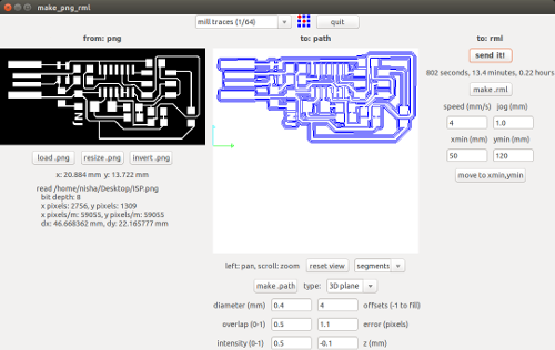
2. Fabmodules for Roland.
We use fabmodules to run the machine. As before, select the input format and output machine.
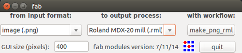
If any rotation or image edition is done, then make sure that resizing of the image is done using resize .png. Invert .png is done to invert the color of the board before milling (in case needed).
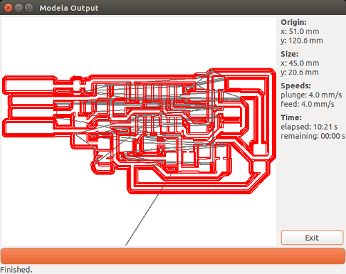
A window appears showing the estimated time for completion of milling and button to start the process. Click on begin milling.
This will send the milling machine into action!
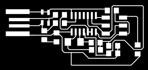
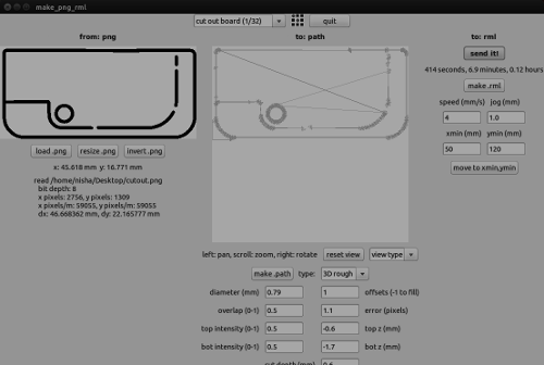
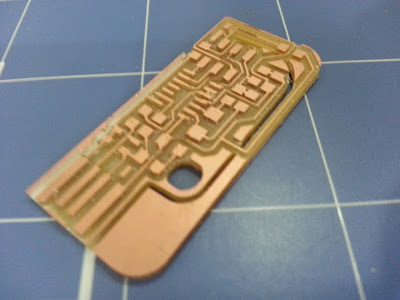
3. Traces, Cutouts
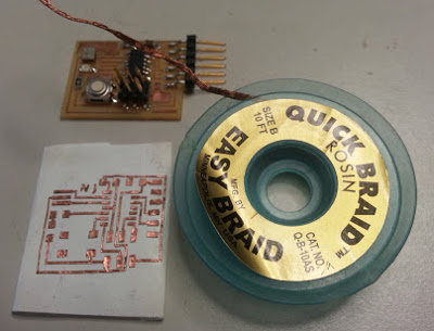
I used Valentin's board as Fab ISP Programmer.
I downloaded the traces and cut outs from here
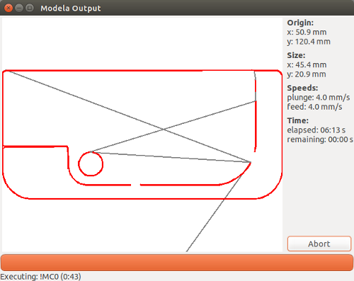
Initially I cut the traces and then the cut outs.
4. Removing the cutout from the copper clad circuit board.
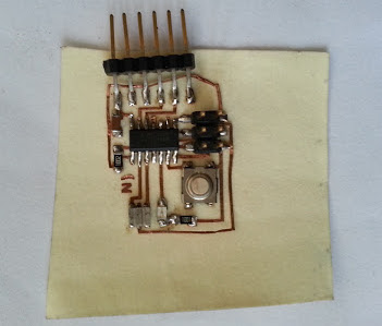
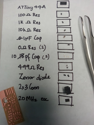
5. Stuffing
6. Soldering
- Don't hold the components too hard with the tweezer. Then it would be the last time you see the smd.
- Start soldering the components from the centre and then along the sides.
- Keep the tip of the soldering rods clean.
- Never forget to turn ON the Fume Fan. Safety comes first.
7. Programming the ATtiny 44A
We need Avrdude (for programming) and GCC (to compile C code). To get GCC and avrdude on Ubuntu, I used tutorials from fabacademy, How To Assemble and Program the FabISP.
Don't forget to power the FabISP Board by using the 6-pin programming header
Download and UnZip the firmware.zip file from the Fab Academy Electronics Production page and move into the newly created firmware directory. Open the firmware directory in terminal.
Now go to the make file generate in folder and open it with text editor. Edit the line in the make file for your programmer. I am using usbtiny to program my board, so I uncommented the below line:
At first on make Program I had an error shown as below:
nisha@nisha-Satellite:~/Downloads/firmware/fabISP_mac.0.8.2_firmware$ make program
avrdude -c usbtiny -P usb -p attiny44 -U flash:w:main.hex:i
avrdude: error: usbtiny_transmit: error sending control message: Operation not permitted
avrdude: initialization failed, rc=-1
Double check connections and try again, or use -F to override this check.
avrdude: error: usbtiny_transmit: error sending control message: Operation not permitted
avrdude done. Thank you.
make: *** [flash] Error 1
I checked the connections again for any loose connections and again did Make Program. This time the process was successful.
nisha@nisha-Satellite:~/Downloads/firmware/fabISP_mac.0.8.2_firmware$ sudo make program
avrdude -c usbtiny -P usb -p attiny44 -U flash:w:main.hex:i
avrdude: AVR device initialized and ready to accept instructions
Reading | ################################################## | 100% 0.00s
avrdude: Device signature = 0x1e9207
avrdude: NOTE: "flash" memory has been specified, an erase cycle will be performed
To disable this feature, specify the -D option.
avrdude: erasing chip
avrdude: reading input file "main.hex"
avrdude: writing flash (2002 bytes):
Writing | ################################################## | 100% 2.02s
avrdude: 2002 bytes of flash written>
avrdude: verifying flash memory against main.hex:
avrdude: load data flash data from input file main.hex:
avrdude: input file main.hex contains 2002 bytes
avrdude: reading on-chip flash data:
Reading | ################################################## | 100% 2.37s
avrdude: verifying ...
avrdude: 2002 bytes of flash verified
avrdude: safemode: Fuses OK (E:FF, H:DF, L:62)
avrdude done. Thank you.
avrdude -c usbtiny -P usb -p attiny44 -U hfuse:w:0xDF:m -U lfuse:w:0xFF:m
avrdude: AVR device initialized and ready to accept instructions
Reading | ################################################## | 100% 0.00s
avrdude: Device signature = 0x1e9207
avrdude: reading input file "0xDF"
avrdude: writing hfuse (1 bytes):
Writing | ################################################## | 100% 0.00s
avrdude: 1 bytes of hfuse written
avrdude: verifying hfuse memory against 0xDF:
avrdude: load data hfuse data from input file 0xDF:
avrdude: input file 0xDF contains 1 bytes
avrdude: reading on-chip hfuse data:
Reading | ################################################## | 100% 0.00s
avrdude: verifying ...
avrdude: 1 bytes of hfuse verified
avrdude: reading input file "0xFF"
avrdude: writing lfuse (1 bytes):
Writing | ################################################## | 100% 0.00s
avrdude: 1 bytes of lfuse written
avrdude: verifying lfuse memory against 0xFF:
avrdude: load data lfuse data from input file 0xFF:
avrdude: input file 0xFF contains 1 bytes
avrdude: reading on-chip lfuse data:
Reading | ################################################## | 100% 0.00s
avrdude: verifying ...
avrdude: 1 bytes of lfuse verified
avrdude: safemode: Fuses OK (E:FF, H:DF, L:FF)
avrdude done. Thank you.
8. Removing the solder jumper.
For this just break the board at the cut out made. A disadvantage which I see in the board is that once the board is broke down, in case you need to configure the board again then it's not possible!
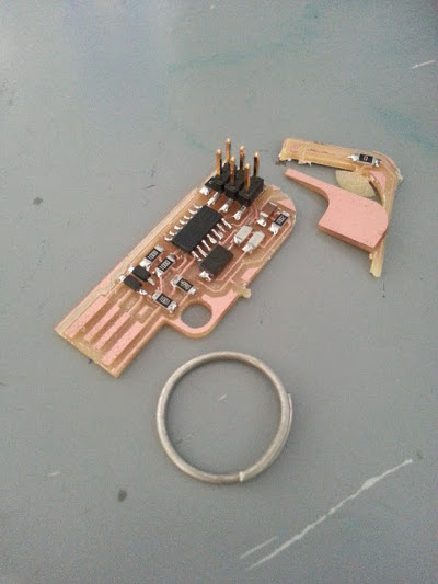
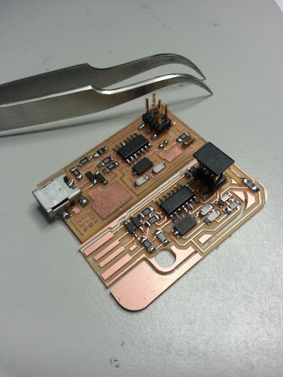
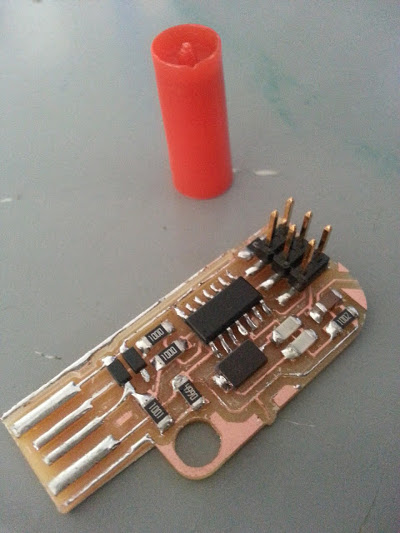
Final Board Shots:
Continuation of Flexible Circuit Cutting...
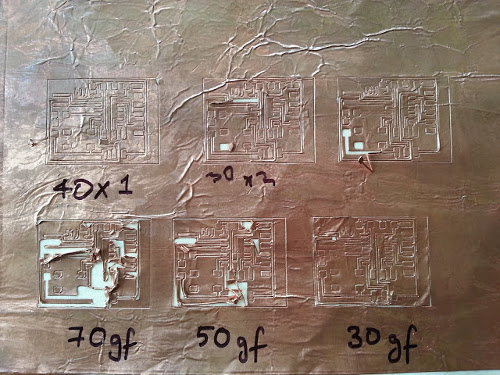
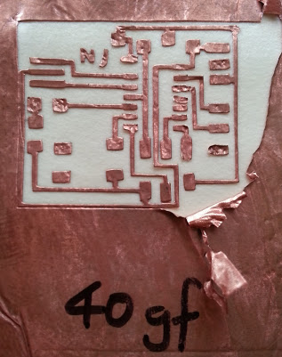
I was able to cut the circuit and remove the unwanted copper sheet parts easily. But I made a mistake by transfering the circuit to the wrong side of epoxy! (Oops, I had to restart the whole process again. Never mind, it was a big learning curve for me. Look before you Do!)
After transfering the copper trace on to the epoxy sheet, stuff the pads with the components as usual. Remember to start stuffing the components from the middle of the board.
The board with stuffing being done.