Week 14 : Output devices
Assignment :
This week we need to add an output device into the existing microcontroller board we have made.
My plan for output device is to develop output board with relay and power supply circuit.
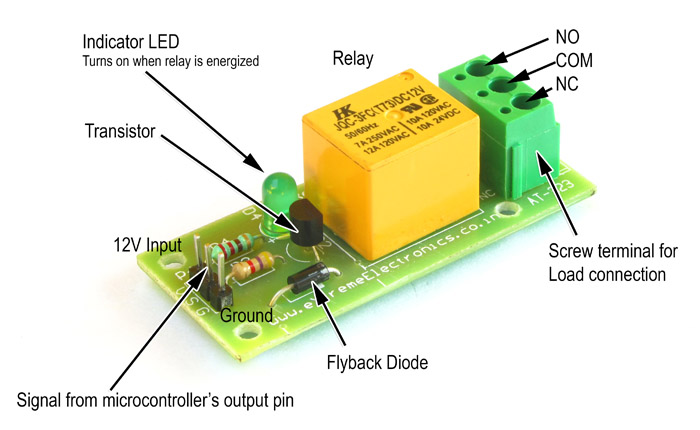
Relay circuit
Relays are devices which allow low power circuits to switch a relatively high
Current/Voltage ON/OFF. For a relay to operate a suitable pull-in and holding
current should be passed through its coil. Generally relay coils are designed
to operate from a particular voltage often its 5V or 12V.
Neil's Schedule page suggests to use
this Solid state relay, which we don't have at our fablab inventory. So, I decided to buy a
relay breakout board to replace it.
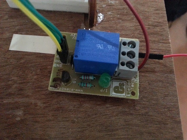
 Break Out board
To supply 12V power to the led strips the relay board's moving contact must close to the
open contact and establish a connection. Also, I use a led driver circuit to get a 12V dc
supply.
Insights from Datasheets
From microcontroller ATtiny 44, I took note on the digital pins and decided to connect the output
over relay to pin 9. Relay needs digital output, that is a HIGH or LOW to turn on or off the led.
The I programmed the board so that PIR senses motion and gives signal to the relay board.
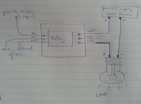 Relay connection with MC and lamp, A paper sketch
Design of Input board modified to include output devices
I made the input board in such a way that I took all the pins of the microcontroller
out so that I can add any output devices and check. Also I added a LED through a 499 ohm
resister to the microcontroller at pin number 6. I used kokopelli to make the board.
design in kokopelli is like a trial and error to find out the right number of pads, yet it's fun.
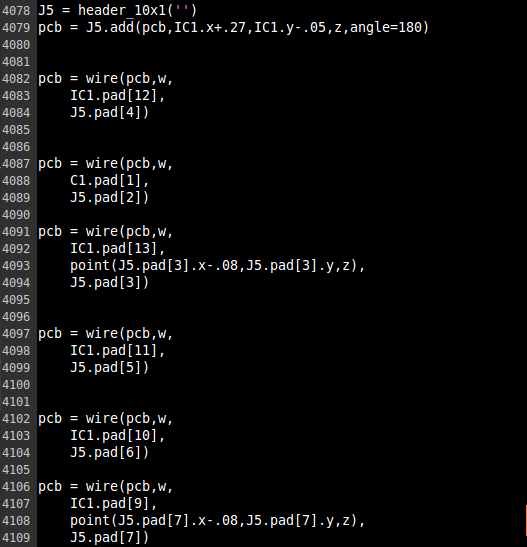 Code made change to take the I/O pins, ground and Vcc out of the board to connect I/O devices
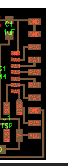 The Header 10*1 is added into the board
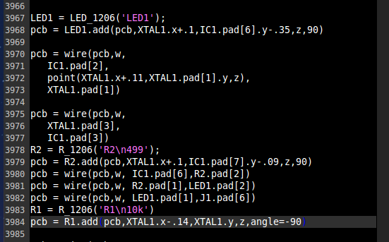 Code made change to add resistor and led at pin no. 6
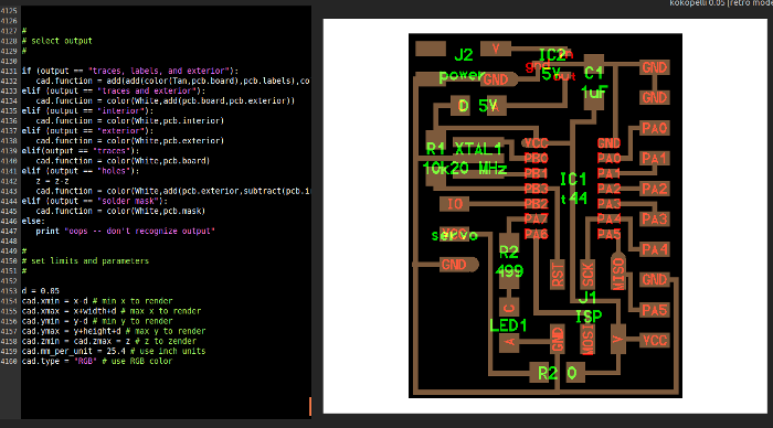 Output at kokopelli
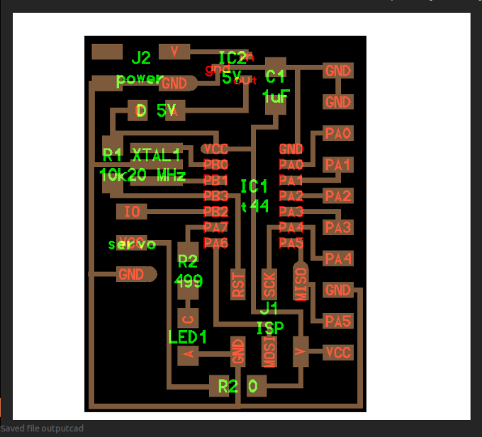 Board made with kokopelli
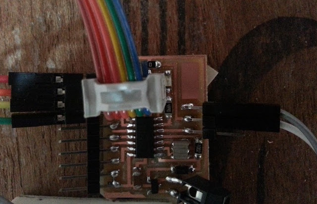 Board with Relay contactors connected through jumper wires.
Design file of the board in kokopelli
I took out a PWM pin seperately and gave it name as servo. So that I can connect a servo motor and
check it out in future.
Programming
I used arduino IDE to program. Here are the code:
#define RELAY1 4 //Defining relay pin 7
int pirPin = 5; //the digital pin connected to the PIR sensor's output A2
int ledPin =7; //7
//SETUP
void setup()
{
pinMode(pirPin, INPUT);
pinMode(ledPin, OUTPUT);
digitalWrite(pirPin, LOW);
pinMode(RELAY1, OUTPUT);
}
//LOOP
void loop(){
if(digitalRead(pirPin) == HIGH)
{
digitalWrite(ledPin,HIGH);
delay(100);
digitalWrite(ledPin,LOW);
delay(100);
digitalWrite(RELAY1,HIGH);
delay(100);
if(digitalRead(pirPin) == LOW)
{
digitalWrite(ledPin,HIGH);
delay(500);
digitalWrite(ledPin, LOW); //the led visualizes the sensors output pin state
delay(500);
digitalWrite(RELAY1,LOW);
delay(500);
}
}
Problem I encountered
Since the relay breakout board has switching between contactors, that involves mechanical
movement of contactors. Not always the relay contactors closed. At times, I had to tap on
the relay board to establish connection. So, realised that mechanical relaysare not a good option
and rather opt for other switching techniques. Also, the breakout board came in with mislabeled
NO, NC and contacter pin. This gave me a hectic battle with voltmeter to find out which pins
were the right ones.
 Break Out board
Arduino program file of the relay circuit
Using MOSFET instead of Relay
Using MOSFET as an alternative to relay has it's own pros and cons. MOSFET being a type of transistor
are much more faster in switching compared to the Relay. Relays are typically on-off devices, and
Transistors can have their voltage drop varied.
Advantages I felt around choosing relay was mainly complete isolation between the activating circuit and the load.
They can switch AC and DC, and be activated by AC or DC. Also, they can be very robust. They also have the
advantage that one can often see if the device is actuated, and one can even hear the actuation in many cases.
But, later on after proceeding with the relay, I realised it was comparitatively more menacing since
there involved mechanical switching between the contactors. The contactors sometimes
did not close and open as desired. Because of this, now I conclude using of MOSFET was
a better option compared to usage of relay for the project.
What I learnt from this week's schedule...
Interfacing relay and microcontroller
Different output devices