Week 12 : Input Devices
This week's assignment seems to be quite important for me. For my smart furniture, I need to use a sensor
to sense the person while he uses the furniture and then use this data to turn on the lights.
Assignment :
This week's assignment is to measure something: add a sensor to a microcontroller board that you have designed and read it.
Things to figure out:
- What sensor and technique to use?
- Powering the board, not from the Computer...
Niel insists on designing a new board using Attiny 45 and adding a sensors
into it. So it is also a practice in designing and fabricating a board.Attiny 45 is much smaller, cheaper 8 pin chip.
One way to get signals in is digitally within through the pin. Each pin can be connected or
disconnected to sense. Each pin can have a pull up resistor too attached to it.
So there are a lot of states just in a pin. I would like to use Attiny 44 and take out all the pins,
so that I could add more input and output devices later on.
Input Devices
My Goal is to learn and do some personal research of different input devices
and then pick on an input device for my project, mill the board with sensor traces
and program the board.
Switch
There are two switches in the inventory. Push Button
and Slide switch. Switch takes in an input as HIGH or LOW, which could be used
as imput to make any changes in output devices.
I don't need a person to mechanically switch on the light's while he is using the
furniture. So, switch is not an option for me.
 Different switch types
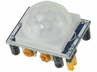
Motion detection Sensor
Sensor Used: Pyroelectric Infrared PIR Motion Sensor Detector Module Hc-sr501
This detects activity. Not a proximity detector but it is activity detector.
It has several nice features including sensitivity adjustment and trigger delay.
Qualitative measurement of activity is done in this sensor. This sensor requires a 5V DC supply.
It can be used to sense the person while he moves, but sensitivity of the device can be an
issue. Franc, suggested to use this sensor for the input board for my project.
 HC-sr501
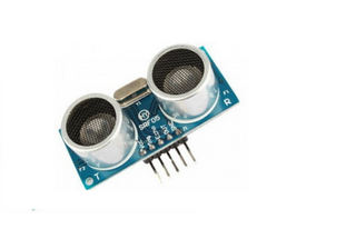
Distance measurement with sonar
Sensor Used: Ultrasonic Module HC-SR04 Distance Sensor
This module includes ultrasonic transmitters, receiver and control circuit.
It's 4 pinned device requies 5V DC Supply and a working current of 15mA. It has
a maximum range of 4m and minimum range of 2cm. The four pins are
- 5V Supply
- Trigger Pulse Input
- Echo Pulse Output
- 0V ground
That's what I learnt from datasheet of the sensor.
 HC-SR04 Module
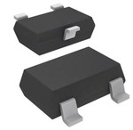
Magnetic field -
Sensor Used: IC Sensor HALL EFFECT SOT23W
This component has packages in both through hole and SMD's. These provide a
voltage output that is proportional to the applied magnetic field. This requires
a supply voltage of 5V (Min:4.5V and Max:5.5V) and supply current,
maximum of 9mA. It's a 3 pin component, with pins being:
- 1. Vcc
- 2. Vout
- 3. GND
 SOT23W
Temperature Sensor
NTC and RTD Thermistors
So, Thermistors are temperature sensing elements, where resistance is in proportion
to small changes in temperature. This resistance can be measured by using a small and
measured direct current, or dc, passed through the thermistor in order to measure
the voltage drop produced. NTC Thermistors are negative temperature coefficient
thermistors. That is the resistance of NTC will decrease as temperature increases.
RTD Thermistors are resistive temperature detectors. Theses are positive temperature
coefficient sensors where resistance rises linearly with temperature rise.
For both SMD flat- chips are available. For those requiring a temperature measurement and varying the output
accordingly, this is a sensor to keep on track.
Light Sensing
Phototransistor
Sensor that can be used: OP580DA.
It's an NPN silicon photodarlington mounted in a minature SMD package having
application in non-contact position sensing and machine automation.
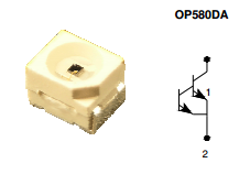 OP580DA
Accelerometer
For measuring the acceleration of a moving or vibrating body. There is Dual axis
accelerometer (MXD6235M) and also three axis accelerometer (ADXL343).
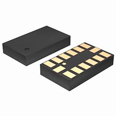 three axis accelerometer-ADXL343
For this week's assignment, I at first choose to build the transmit-receive version of
the step response circuit. Variations of this circuit can be used to measure resistance,
capacitance, inductance, position, pressure, proximity, tilt, acceleration,
humidity, touchpad, multitouch, etc. Using this I thought to control the relay driver. But,
later I choose PIR sensor to be used for my input board. If I get enough time, I'll come back and
explore on the step response circuit.
Making the circuit board
Making of the circuit board came out after doing many changes. Initially, I thought of using
an ATtiny 45 as the microcontroller. I needed only very few I/O pins which needs to be connected to
PIR, relay driver, and indicator LED. But, later on franc suggested to use a micro controller
with more pins, so that you can use it to extend the project later on. I've used ATtiny44 as
the microcontroller. In order to provide external supply of 5V I've
added voltage regulator LM7805. I also added a LED to indicate the status of whether PIR Detects motion or
not. The PIR sensor HC-SR 501 has three pins, 5V, GND and Output pin. I'm connecting the output pin to the pin
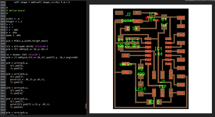
5 of the microcontroller. I'm connecting LED over pin 7 through a 499 ohm resistor. I used kokopelli for designing the
circuit.
Kokopelli being used to define board
The I/O pins taken out from the board using jumpers.
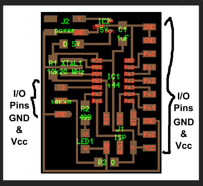
Board Trace
Board Cut out

Design File of the input board in kokopelli
Stuffed Board
Programming the board
I used Arduino IDE to program the board.
int pirPin = 5; //the digital pin connected to the PIR sensor's output A2
int ledPin =7;
//SETUP
void setup()
{
pinMode(pirPin, INPUT);
pinMode(ledPin, OUTPUT);
digitalWrite(pirPin, LOW);
}
}
//LOOP
void loop(){
if(digitalRead(pirPin) == HIGH)
{
digitalWrite(ledPin,HIGH);
delay(100);
digitalWrite(ledPin,LOW);
delay(100);
}
if(digitalRead(pirPin) == LOW)
{
digitalWrite(ledPin,HIGH);
delay(500);
digitalWrite(ledPin, LOW); //the led visualizes the sensors output pin state
delay(500);
}
}
Download File
Arduino program for PIR sensor
Step Response board
The ATtiny 45 microcontroller has only 8 pins, so it has limited number of I/O pins and
all are used except for the pins used for ISP. It is possible to use the pins used for
In-System Programmer(ISP) as I/O pins when ISP is not connected. I've noticed that the MISO
and MOSI connections of the ISP is connected to the PB0 and PB1 pins and these could be
used as an output for relay and a status indicator LED.
The idea is to place the foil papers with a sandwiched thick form. When one of the
foil [TX] is pressed to the RX foil there will be an increases readout value proportionally to
the force applied. Take a threshold value of this value above which the relay [output device] is
given signal. So when Relay is given HIGH signal, this turns on the LED strips inturn.
Board design
I did the board design in Eagle. In eagle, once the components are dragged in from the library, we can
use auto routing feature to connect between the components while board designing. But sometimes the auto
routing will not give you all the wire connections. So, its better to manually connect the components, which
is a day task indeed. I have added indicator LED and Transister BC 547, these are the changes I made to the niel's
board.
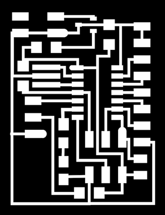
Board png images...
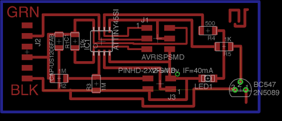 Whole Circuit
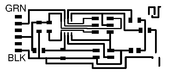 traces
 Outline and drill hole
The relay needs to be connected to the microcontroller through a transister. The transister is used
to control the relay. The transistor is driven into saturation (turned ON) when a LOGIC 1 is written
on the PORT PIN thus turning ON the relay. The relay is turned OFF by writing LOGIC 0 on the port pin.
Both relay and the indicator LED are my output devices.
I will describe my circuit for relay and power supply unit in the output device assignment page. I milled the
traces in the copper clad using modella and 1/64 inch bit. I couldn't cut the outline, since the inventory went
short of 1/32 inch bits. I thought to use the chain saw to cut the board out and later only realised that the
holes needs to be drilled for the transister I have used, which is a through hole component. Later I tried to
drill holes manually, but then the smallest of the drill bit available was still drilling a big hole. I'm trying to
find a solution for this so that I can drill hole and complete stuffing the board soon and start programming the board.
Design Files of stepresponse board
.sch file, .brd file
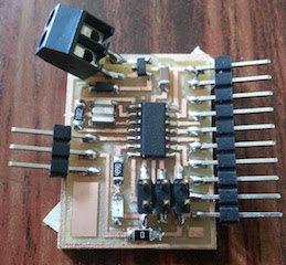
Stuffed Board
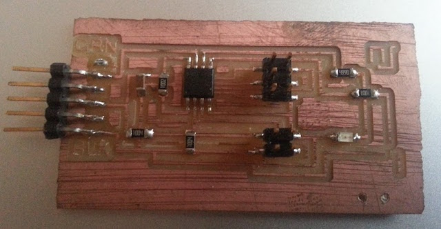
Programming the board
I tried to program the board. At first tried to check whether the LED was working perfectly so as to show the
output on the board. But then, as I plugged in the board through FabISP, the LED turns on.
I checked for short connections, found one removed it. Further checked, still the LED remains on.
Later on, checked for if the resistor is of right value, it too is. I'm trying to debug the board.
What I learnt from this week's schedule...
Learnt about different input boards
Found out which input board is apt for my project
Tried a hand on step response board...it still needs more exploration.