She really likes walking during rainy ugly days...
But she does not like to walk on dirty and dry grounds...
To be honest, Fab Snail does not like many things...like polluted air or muggy days...
She is not the only one who doesn't like all that, just like all the other snails...
The difference is that if Fab Snails is not happy, she can turns into a real stalker!
(Also on your mobile -.-)
So take care of Fab Snail, she is a good snail...
She is just different from the other snails!"
Weekly Assignment
The weekly assignment were:
- Read a microcontroller data sheet
- Program your board to do something, with as many different programming languages and programming environments as possible
Software and Hardware
The software that i've used this week are:
- Eclipse Mars + AVR plugin: used as a programming environment
- Atmel Studio 7: used as a programming environment
- Arduino IDE: used as a programming environment
Concerning the hardware:
- FabISP: the programmer that i've build during the 4th week
- Hello board: the board that i've build during the 6th week
- Satshakit: the board that i've build during the 6th week
Workflow:
- Program the attiny44 on the Hello board through Arduino IDE and Arduino libraries
- Program the atmega328p on the Satshakit using C language and unix CLI
- Program the attiny44 on the Hello board using C language and Eclipse
- Program the atmega328p on the Satshakit using C language and Eclipse
- Program the atmega328p on the Satshakit using C language and Atmel Studio
Attiny44 + Arduino IDE + Arduino libraries
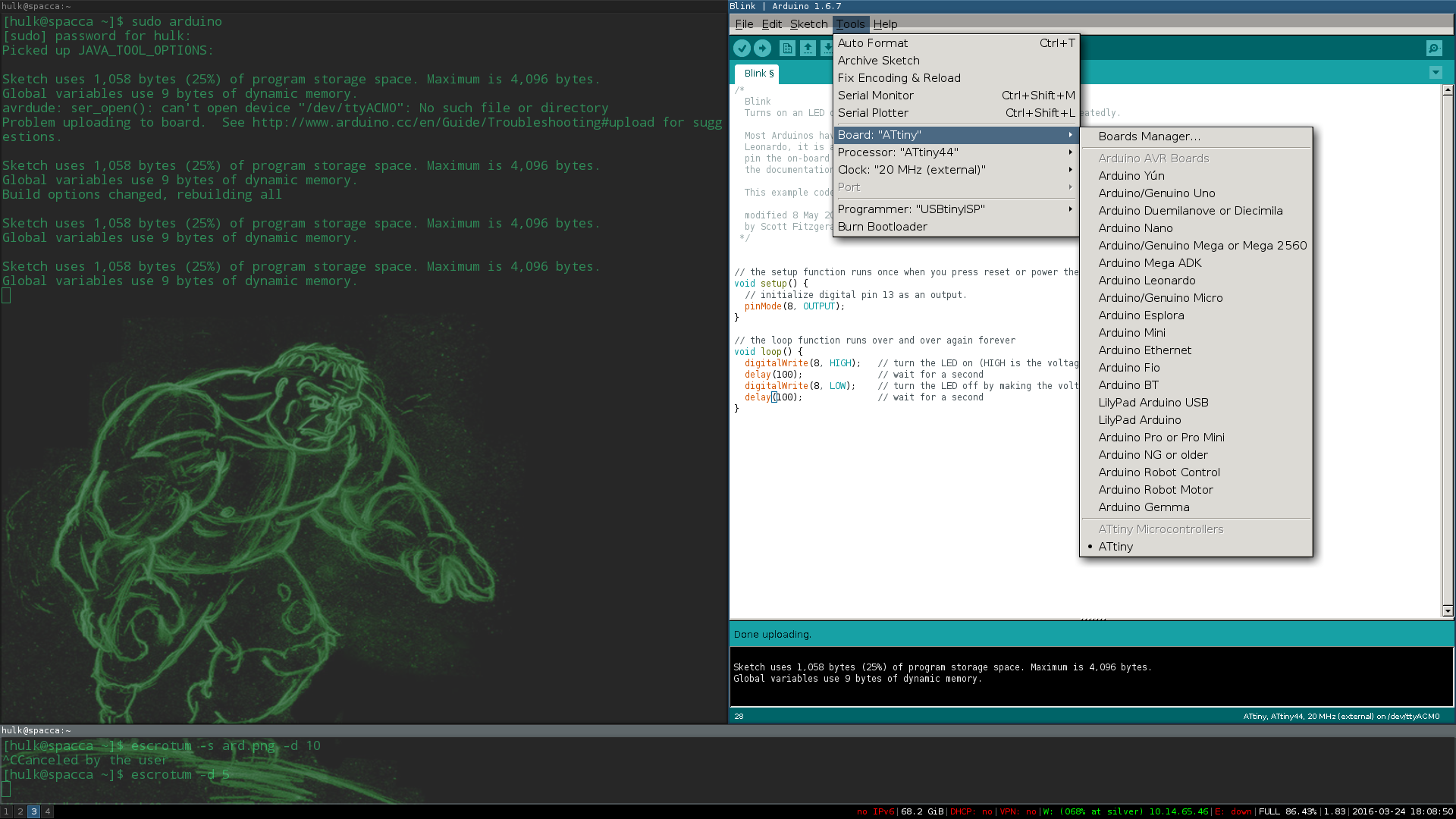
I was already very familiar with the Arduino IDE so i've started to programm the boards from here.
To use Arduino IDE to program the attiny, is necessary to download and unzip in the folder xxxxxx
the libraries for the microcontrollers.
In this way is possible to select the Attiny44 from the list of programmable devices.
This is the sketch that i've used to blink the led while the button is pressed (DOWNLOAD)
void setup() {
// initialize digital pin 13 as an output.
pinMode(8, OUTPUT);
}
void loop() {
digitalWrite(8, HIGH); // turn the LED on (HIGH is the voltage level)
delay(100); // wait for a second
digitalWrite(8, LOW); // turn the LED off by making the voltage LOW
delay(100); // wait for a second
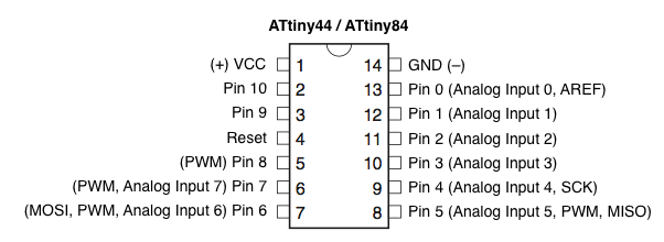
}And this is the attiny44/arduino pins correspondence:
To upload the sketch is necessary to select "upload using a programmer" from the "Sketch" tab in the IDE. Here the result:
VIDEO_HELLO_BLINK
Satshakit + CLI
After i've succesfully programmed the hello board, I moved to the Satshakit and to C language.
I had a previous knowledge in C but i've never programmed an AVR microcontroller.
At this point it was crucial to open the datasheet of the atmega328p...
...and reading the datasheet from the beginning was really soporific -.-.
So i've decided to connect to the board an analog photocell (which i want to include in my final project) and i've started to
look inside the datasheet to find the part related to the ADC converter.
First i've wired the Satshakit to the FabISP in this way:
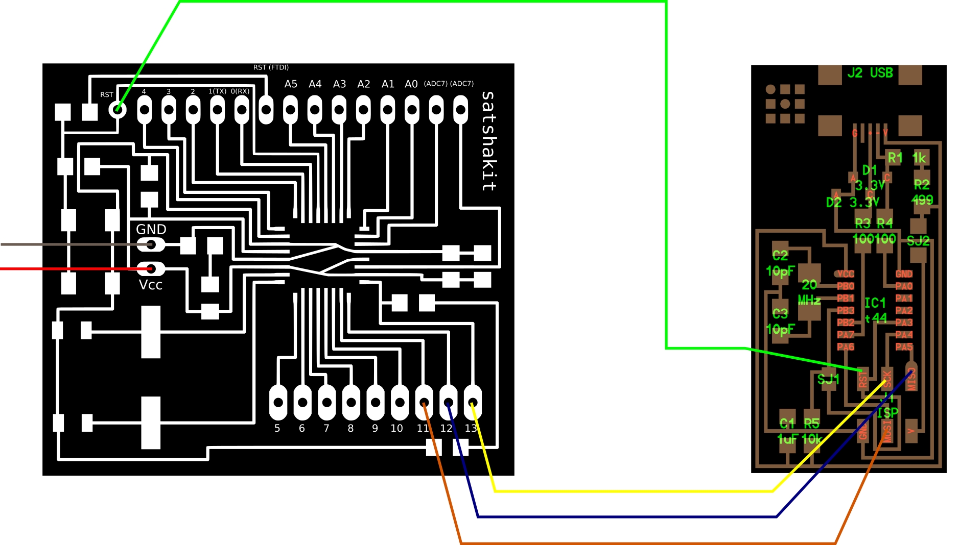
And then i've added:
- A photocell connected from one side to VCC and from the other to a 1K resistor, to ground and to A0 pin of the board
- A led connected from one side to ground and from the other side to pin 10 of the board (which corresponds to PB2 of the MCU)
At this point i went back reading the datasheet and well...i get lost again!
So i've started to google "avr ADC" and i've found this awesome tutorial on AvrFreaks.
Reading the tutorial, each time that i've found a new register I moved to the datasheet to find all the information on that register.
In the first version of the code I've written for each line is the correspondent page of the datasheet in which is possible to find all the information on that register:
#include

int main (void)
{
   DDRB |= (1 << PB2); // Set LED pin as output ("Configuring the pin", pg 76)


   ADCSRA |= (1 << ADPS2) | (1 << ADPS1) | (1 << ADPS0); // Set ADC prescalar to 128 - 125KHz sample rate @ 16MHz (Ch. 24, "Prescaling and Conversion Timing", pg.240 - pg.249)

   ADMUX |= (1 << REFS0); // Set ADC reference to AVCC (Ch. 24, pg. 248)
   ADMUX |= (1 << ADLAR); // Left adjust ADC result to allow easy 8 bit reading (Ch. 24, pg. 247, pg. 249, pg. 250)

   // No MUX values needed to be changed to use ADC0 (pg. 249, table 24-4)

   ADCSRA |= (1 << ADFR);  // Set ADC to Free-Running Mode (WRONG! there is no ADFR bit inside the ADCSRA for the atmega328p, pg. 239)
   ADCSRA |= (1 << ADEN);  // Enable ADC (pg. 238)
   ADCSRA |= (1 << ADSC);  // Start A2D Conversions (pg. 239)

   for(;;)  // Loop Forever
   {
		if(ADC < 128) //Reading the results (p. "ADC conversion result, "pg. 247)
		{
			PORTB |= (1 << PB2); // Turn on LED (pg. 76)

		}

		else
		{
			PORTB &= ~(1 << PB2); // Turn off LED (pg. 76)

		}

	}

}
I've used this sketch only as a starting point and i've not even uploaded it on the microcontroller.
After the analysis of this code, I've had a more precise idea on the analog-to-digital conversion and the datasheet started to be more "readable".
Then i've started writing a new piece of code with having in mind the information i've learned from the datasheet.
#include "avr/io.h"
#include "util/delay.h"
#include "avr/pgmspace.h"


#define output(directions,pin) (directions |= pin) // set port direction for output
#define input(directions, pin) (directions &= (~pin)) //set port direction for input
#define set(port,pin) (port |= pin) // set port pin
#define clear(port,pin) (port &= (~pin)) // clear port pin
#define delay() _delay_ms(10)

#define led_pin (1 << PB2)
#define adc_pin 0


int main(void){


  output(DDRB,led_pin);       //write 1 in DDRB.PB2 (set the pin as output)
  clear(PORTB,led_pin);       //be sure that the led is turned off (0 in PB2)
  ADCSRA |= (1 << ADEN);      //Power up the ADC
  ADMUX	&=	0xf0;             //Ensure the zeroes inside MUX3..0
  ADMUX	|=	adc_pin;          //Set MUX3...0 accordingly to adc_pin we defined (0 in this case)

  for(;;){                    //Loop
    	ADCSRA |= (1 << ADSC);  //Start the conversion
      delay();                //Wait the end of the conversion
      if(ADC > 512){          //Read the result of the conversion from the ADC register
        PORTB |= (1 << PB2);  //If ADC value is above 512 turn led on
      }
      else {
        PORTB &= ~(1 << PB2); //Else turn led off
      }
    }

return 0;
}
To upload the code to the microcontroller i've first modified the makefile of the hello board in this way:
PROJECT=adc
SOURCES=$(PROJECT).c
MMCU=atmega328p
F_CPU = 16000000
CFLAGS=-mmcu=$(MMCU) -Wall -Os -DF_CPU=$(F_CPU)
$(PROJECT).hex: $(PROJECT).out
avr-objcopy -O ihex $(PROJECT).out $(PROJECT).c.hex;\
avr-size --mcu=$(MMCU) --format=avr $(PROJECT).out
$(PROJECT).out: $(SOURCES)
avr-gcc $(CFLAGS) -I./ -o $(PROJECT).out $(SOURCES)
program-bsd: $(PROJECT).hex
avrdude -p m328p -c bsd -U flash:w:$(PROJECT).c.hex
program-dasa: $(PROJECT).hex
avrdude -p m328p -P /dev/ttyUSB0 -c dasa -U flash:w:$(PROJECT).c.hex
program-avrisp2: $(PROJECT).hex
avrdude -p m328p -P usb -c avrisp2 -U flash:w:$(PROJECT).c.hex
program-avrisp2-fuses: $(PROJECT).hex
avrdude -p m328p -P usb -c avrisp2 -U lfuse:w:0x5E:m
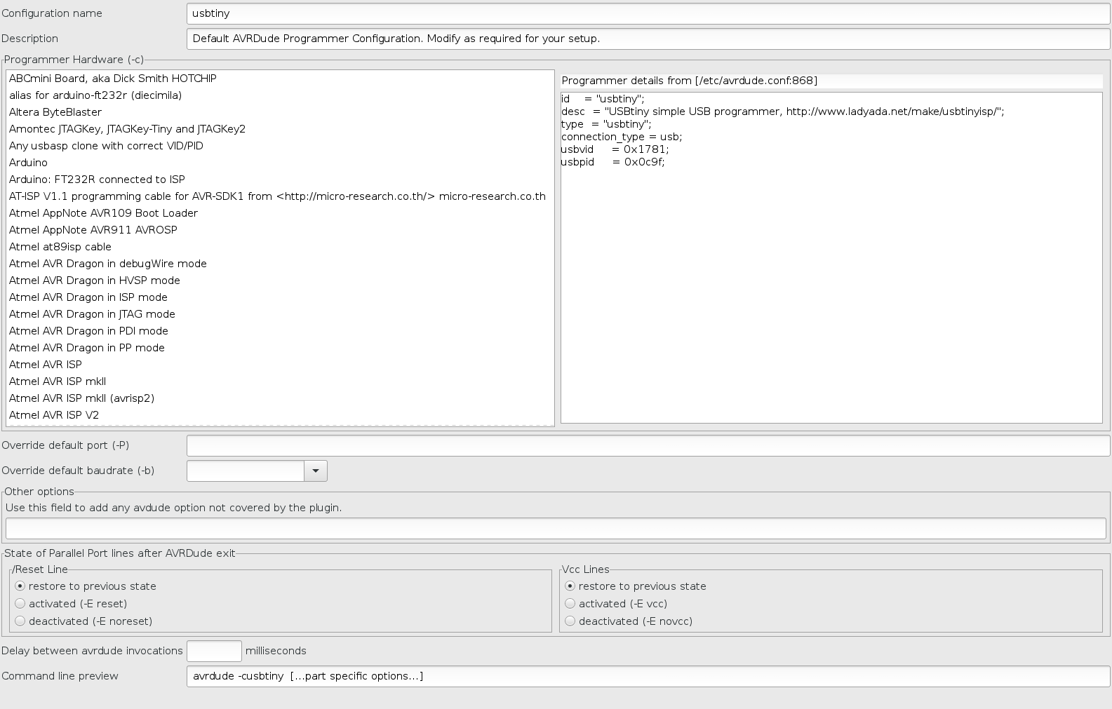
program-usbtiny: $(PROJECT).hex
avrdude -p m328p -P usb -c usbtiny -U flash:w:$(PROJECT).c.hex
program-usbtiny-fuses: $(PROJECT).hex
avrdude -p m328p -P usb -c usbtiny -U lfuse:w:0x5E:m
program-dragon: $(PROJECT).hex
avrdude -p m328p -P usb -c dragon_isp -U flash:w:$(PROJECT).c.hex
In particular, i've changed the MMCU at the beginning with "atmega328p" (used by the Satshakit) and the options -p of the avrdude command to m328p which corresponds to the atmega328p; the F_CPU to 16000000. At this point cd to the folder that contains the makefile and the .c file and run
make -f xxx.make
  sudo make -f xxx.make program-usbtiny-fuses
  sudo make -f xxx.make program-usbtiny
By watching the behavior of the blinking led, i've realized that the delay was too high so i wnt back to the datasheet to understand how to check if the conversion is finished without the need to put an arbitrary delay. At page 249 of the datasheet is written that setting the ADSC bit inside the register ADC start the conversion and that ADSC become zero again when the conversion is finished. So i've realized that by looking at the value of this bit i could have known when the conversion was finished. So i've modified the code again and this is the final version:
#include "avr/io.h"
#include "util/delay.h"
#include "avr/pgmspace.h"


#define output(directions,pin) (directions |= pin) // set port direction for output
#define input(directions, pin) (directions &= (~pin)) //set port direction for input
#define set(port,pin) (port |= pin) // set port pin
#define clear(port,pin) (port &= (~pin)) // clear port pin

#define led_pin (1 << PB2)
#define ADC_PIN 0
#define ADC_THRESHOLD	512

uint16_t adc_read(uint8_t adcpin);

int main(void){


  output(DDRB,led_pin);       //write 1 in DDRB.PB2 (set the pin as output)
  clear(PORTB,led_pin);       //be sure that the led is turned off (0 in PB2)

  ADCSRA |= (1 << ADEN);      //Power up the ADC

  ADMUX	&=	0xf0;        //Ensure the zeroes inside MUX3..0
  ADMUX	|=	ADC_PIN;     //Set MUX3...0 accordingly to adc_pin we defined

  for(;;){                    //Loop
      if (adc_read(ADC_PIN) > ADC_THRESHOLD)
        PORTB |= (1 << PB2);  //Turn led on
      else
        PORTB &= ~(1 << PB2); //Else turn led off
      }
    }

return 0;
}


uint16_t adc_read(uint8_t adcpin) {

	ADMUX	&=	0xf0;     //Ensure the zeroes inside MUX3..0
	ADMUX	|=	adcpin;   //Set MUX3...0 accordingly to adc_pin we defined

	ADCSRA |= (1 << ADSC);    //Start the conversion

	while ( (ADCSRA & (1 << ADSC)) ); //Do nothing until the conversion is finished

	return ADC;               //Return the value of the conversion
}
I've just added a function which do the conversion, wait until the end of the operation (by reading the ADCSRA bit of the ADC register to check if it is 0) and return the result.
Here is a video of the program in action:
VIDEO_SATSHA
Eclipse Mars + AVR Plugin
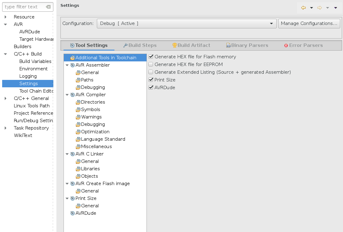
To test more environment, i've used Eclipse + AVR plugin.
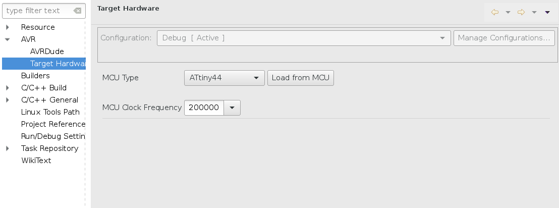
To setup the environment i've folowed this tutorial
and the followings are some screenshots about the settings that i've modified:
I've used this sketch and the hello board + FabISP programmer:
#include "avr/io.h"
#include "util/delay.h"
#include "avr/pgmspace.h"

#define led_delay() _delay_ms(5)

int main(void){

PORTB &= ~(1 << PB2);
DDRB |= (1 << PB2); //output led pin PA7
PORTA |= (1 << PA7);
DDRA &= ~(1 << PA7); //input button pin PB2


while(1){
if((PINA & (1 << PA7))==0){
  PORTB |= (1 << PB2);
}
else{
  PORTB &= ~( 1<< PB2);
}

}

}
Everything worked and i got this confirmation mesages from the console inside Eclipse:
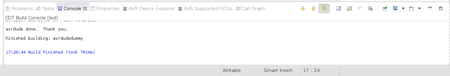
After flashing on the hello board, i've moved to the Satshakit. I've modified the settings of Eclipse accordingly to the new board (MCU=atmega328p , F_CPU=16000000 Hz) and i've slightly modified the code to include an interrupt handling routine (pg. 57-65 of the datasheet):
#include "avr/io.h"
#include "util/delay.h"
#include "avr/pgmspace.h"
#include "avr/interrupt.h"

#define output(directions,pin) (directions |= pin) // set port direction for output
#define clear(port,pin) (port &= (~pin)) // clear port pin

#define led_pin (1 << PB2)
#define ADC_PIN 0
#define ADC_THRESHOLD	512


ISR(ADC_vect){
	ADCSRA |= (1 << ADSC);
	while ( (ADCSRA & (1 << ADSC)) );
	 if (ADC > ADC_THRESHOLD)
	     PORTB |= (1 << PB2);  //Turn led on
	 else
		 PORTB &= ~(1 << PB2); //Else turn led off

}

int main(void){


  output(DDRB,led_pin);       //write 1 in DDRB.PB2 (set the pin as output)
  clear(PORTB,led_pin);       //be sure that the led is turned off (0 in PB2)

  ADCSRA |= (1 << ADEN);      //Power up the ADC

  ADMUX	&=	0xf0;        //Ensure the zeroes inside MUX3..0
  ADMUX	|=	ADC_PIN;     //Set MUX3...0 accordingly to adc_pin we defined

  ADCSRA |= (1 << ADIE);
  sei();
  ADCSRA |= (1 << ADSC);
      //Start the conversion

  while(1);
}
And it worked.
Atmel Studio
After i've tried Eclipse, i've moved to Atmel studio. At the beginning i was not
happy to move to this environment because is windows-only but i must admit that
once i've tried it, i've found it really confortable and handy.
The IDE is full of functionality but i had to make some adjustments in order to use it with
the FabISP as a programmer.
First of all, i had installed the Win-AVR package
which contains the avr-gcc toolchain.
Then, i've started the IDE and i've created a new "GCC C Executable Project":
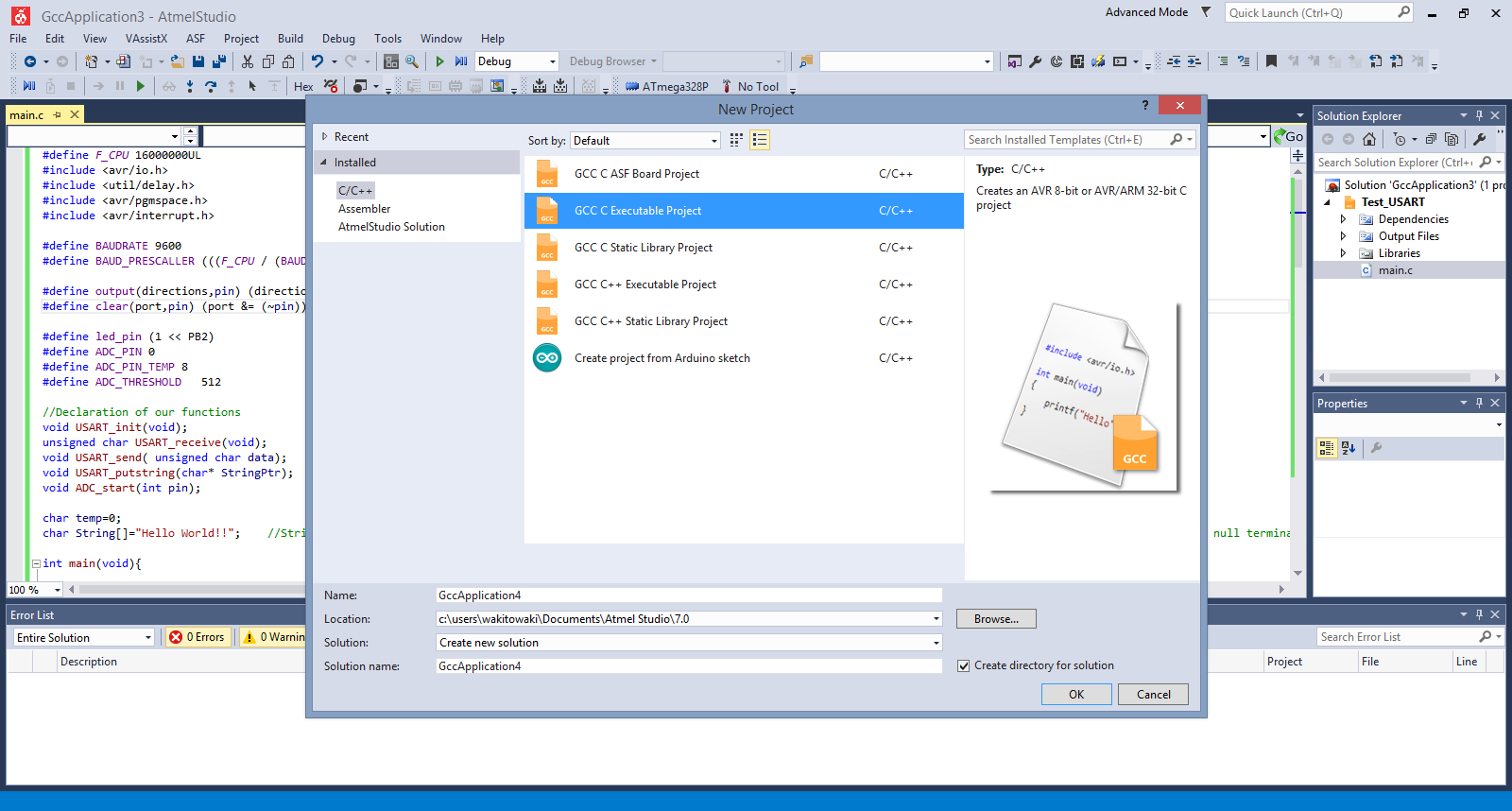
For a first try, i've used the same code that i've used in eclipse for the photocell
and the led.
Then i've configured the programmer. I've followed this tutorial
but i could not found the "External Tool" option under the "Tools" tab of the menu. After some tries,
the solution was to enable the "Advanced Profile" under the "Tools"-->"Set Profile" as shown in the picture below:
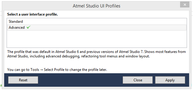
After i've selected "Advanced", the "External Tools" option became visible.
Then i've added a new external tool as shown in the picture:
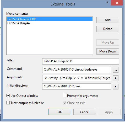
In the "Command" option, i've added the path to my avrdude.exe file (which is installed through the Win-AVR package);
In the arguments, i've used the following string:
-c usbtiny -p m328p -v -v -v -U flash:w:$(TargetDir)$(TargetName).hex:i
I've changed the argument of -p option accordingly to the target MCU that I wanted to program (in my case was the atmega328P mounted on the satshakit, for the attiny44 the option must be -p t44).
To compile the code, select "Build"-->"Build project" from the menu and check the if there are some errors from the console.
Now, I was able to upload the program to the board by selecting "Tools"--->"FabISP ATmega328p" (the tool that i've just created).
After I've checked that the environment was properly setted up and i was able to flash the code on the MCU, i've started to work on the code to improve my previous version. I've decided to try to read the internal temperature sensor of the MCU and to implement a serial communication between the MCU and the computer.This is the first version of the code but I'm still working on it. In the comments is written what i've understand from the datasheet (the chapter related to the USART starts at pg. 170):
#define F_CPU 16000000UL
#include "avr/io.h"
#include "util/delay.h"
#include "avr/pgmspace.h"
#include "avr/interrupt.h"

#define BAUDRATE 9600
#define BAUD_PRESCALLER (((F_CPU / (BAUDRATE * 16UL))) - 1) //pg. 173 datasheet

#define output(directions,pin) (directions |= pin) // set port direction for output
#define clear(port,pin) (port &= (~pin)) // clear port pin

#define led_pin (1 << PB2)
#define ADC_PIN 0
#define ADC_PIN_TEMP 8
#define ADC_THRESHOLD	512

//Declaration of our functions
void USART_init(void);
unsigned char USART_receive(void);
void USART_send( unsigned char data);
void USART_putstring(char* StringPtr);
void ADC_start(int pin);

char temp=0;
char String[]="Hello World!!";

int main(void){

	USART_init();        //Call the USART initialization code
	output(DDRB,led_pin);       //write 1 in DDRB.PB2 (set the pin as output)
	clear(PORTB,led_pin);       //be sure that the led is turned off (0 in PB2)

	ADC_start(ADC_PIN_TEMP);
	temp=ADC;

	while(1){        //Infinite loop
		USART_send(temp);    //Pass the temp to the USART_send function and sends it over the serial
		_delay_ms(5000);        //Delay for 5 seconds so it will re-send the value every 5 seconds
	}

	return 0;
}

void USART_init(void){

	UBRR0H = (uint8_t)(BAUD_PRESCALLER>>8); // Load upper 8-bits of the baud rate value into the high byte of the UBRR register
	UBRR0L = (uint8_t)(BAUD_PRESCALLER);  // Load lower 8-bits of the baud rate value into the low byte of the UBRR register
	UCSR0B = (1 << RXEN0)|(1 << TXEN0);  // Turn on the transmission and reception circuitry
	UCSR0C = (3 << UCSZ00); //pg 194, set 011 bit to define 8-bit char-size
}

unsigned char USART_receive(void){

	while(!(UCSR0A & (1 << RXC0)));
	return UDR0;

}

void USART_send( unsigned char data){

	while(!(UCSR0A & (1 << UDRE0)));
	UDR0 = data;

}

void USART_putstring(char* StringPtr){

	while(*StringPtr != 0x00){
		USART_send(*StringPtr);
	StringPtr++;}

}

void ADC_start(int pin){

	ADCSRA |= (1 << ADEN);      //Power up the ADC

	ADMUX	&=	0xf0;        //Ensure the zeroes inside MUX3..0
	ADMUX	|=	pin;         //Set MUX3...0 accordingly to adc_pin we defined

	ADCSRA |= (1 << ADIE);
	sei();
	ADCSRA |= (1 << ADSC);  // start conversion
}

ISR(ADC_vect){
	ADCSRA |= (1 << ADSC);
	while ( (ADCSRA & (1 << ADSC)) );
	if (ADC > ADC_THRESHOLD)
	PORTB |= (1 << PB2);  //Turn led on
	else
	PORTB &= ~(1 << PB2); //Else turn led off

}
For the part related to the ADC conversion, i've found from the datasheet that the ADC8 pin is the channel from which is possible to read the value of the temperature sensor. So i've used the same procedure that i've previously used for reading the photocell but i've changed the ADMUX value by passing to the ADC_start function the pin 8.
The most complicated part was the one related to the USART configuration. At the beginning, i've started to look at the datasheet (pg. 170) but this part is really full of information. So i've decided to use a lighter approach and i've started to google for some "condensed" explaination of the USART implementation on avr MCUs. Here is a list of tutorial that i've found really useful as a starting point:
I still have to test my code but if the USART communication will work, the next improvement will be to set up multiple ADC inputs with interrupts in order to use more than one sensor at a time. I've found this other tutorials on how to setup multiple ADC channels:
Both the tutorials do not have an interrupt handling routine which is what i want to implement.
To conclude i want to point out a nice feature of Atmel Studio which is the possibility to access the datasheet directly from the program. It is sufficient to click on a register in the code and then press F1 to have the datasheet opened at the right page.
Update
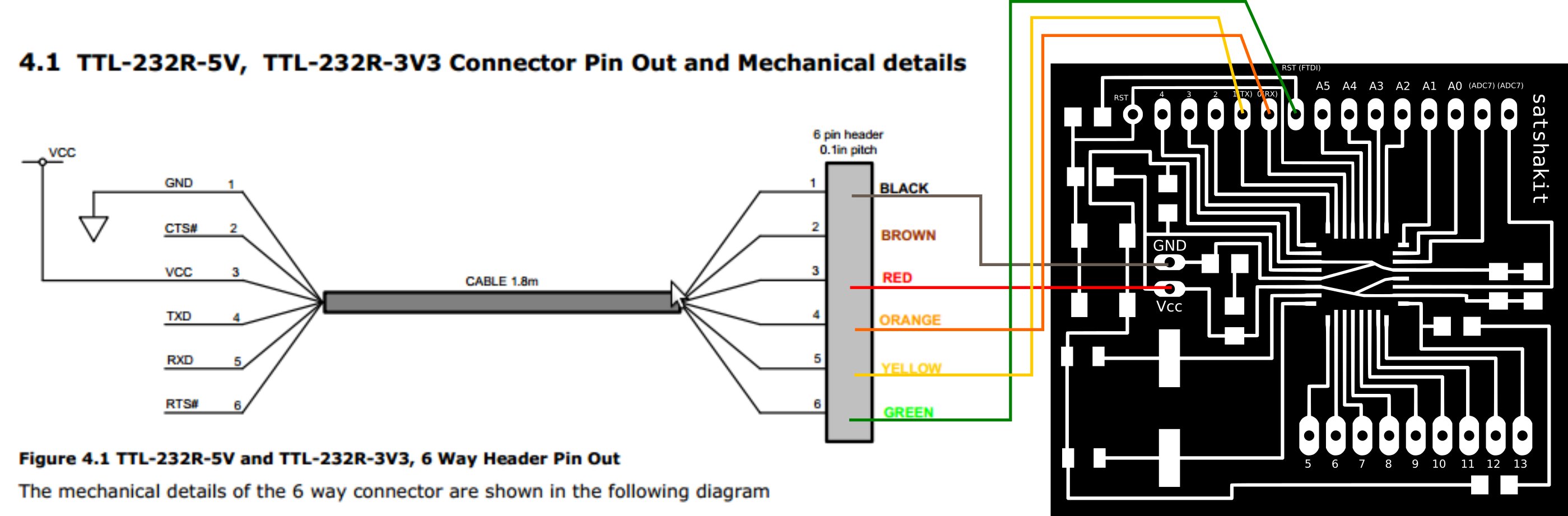
I've tried to connect this adapter to the satshakit
to check the program i wrote in a serial terminal.I've connected the satsha and the FTDI adapter in this way:
But when i've tried to open the serial terminal, i was not able to see any data. By looking at the specific of
the Sparkfun adapter i've found the following:
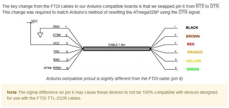
So i've decided to write a simpler code to test only the USART communication. Moreover,
i've decided to burn the Arduino bootloader on the satshakit and to use the Arduino IDE to upload the code
to the board (the procedure is described here).
The code that i've used is the following:
#define F_CPU 16000000
#include "avr/io.h"
#include "util/delay.h"


#define BAUD 9600
#define BRC ((F_CPU/16/BAUD) - 1)

int main (void)
{
	UBRR0H = (BRC >> 8);
	UBRR0L = BRC;

	UCSR0B = (1 << TXEN0);
	UCSR0C = (1 << UCSZ01) | (1 << UCSZ00);
	while(1)
	{
		UDR0 = '8';
		_delay_ms(1000);
	}
}
Then i've used Tera Term, a terminal emulator, to check the serial port.
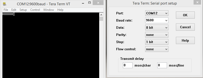
And this time the communication worked.
I will try to adjust the code to use the USART communication combined with the ADC converter to check if i can read the temperature values from the internal temperature sensor of the MCU.
Conclusions
I've really liked this week. Reading the datasheet was really hard at the beginning because i've found that
document really full of information. Once i've familiarized with the basic organization of the datasheet,
it started to become a foundamental instrument to understand what to do to properly program the MCU. To be honest,
the majority of the information for each chapter that i've explored, is still not clear (especially the theorical stuff)
but at least, i've started to be familiar with registers and operations among them.
For this week i've used only two languages (which can be considered the same because arduino language is a simplified C) and
i whis have tried more but honestly speaking, i've preferred to put the accent on the datasheet reading and on the understanding
of the different register that i've used.On the other hand, i've tried 4 different environment and i found very confortable with both
Eclipse and Atmel Studio.
There are a huge amount of material on the web on the AVR programming so, combining
tutorials and guides with the datasheet reading was really useful.
I've also explored some of MCU functionalities that i will use in my final project (eg. ADC conversion and interrupts).