She really likes walking during rainy ugly days...
But she does not like to walk on dirty and dry grounds...
To be honest, Fab Snail does not like many things...like polluted air or muggy days...
She is not the only one who doesn't like all that, just like all the other snails...
The difference is that if Fab Snails is not happy, she can turns into a real stalker!
(Also on your mobile -.-)
So take care of Fab Snail, she is a good snail...
She is just different from the other snails!"
Weekly Assignment
The weekly assignments for this week were:
- Redraw the echo hello-world board
- Add (at least) a button and LED (with current-limiting resistor)
- Check the design rules, and make it
- Optional: simulate its operation
Software and Hardware
The software that i've used this week are:
- CadSoft EAGLE PCB Design Software: used for designing the Schematics and the PCBs
- Fabmodules: used for creating the .rml files used for milling the PCBs
- Gimp: used for editing the .png files exported from eagle
Concerning the hardware:
- Roland SRM20: CNC mill
PCB Design
I was realatively new to Eagle but i had a previous knowledge on electronics due to my background.
To familiarize with the software and with the main commands, i've followed this
tutorial from the fabarchive and the tips that our instructor gave to us.
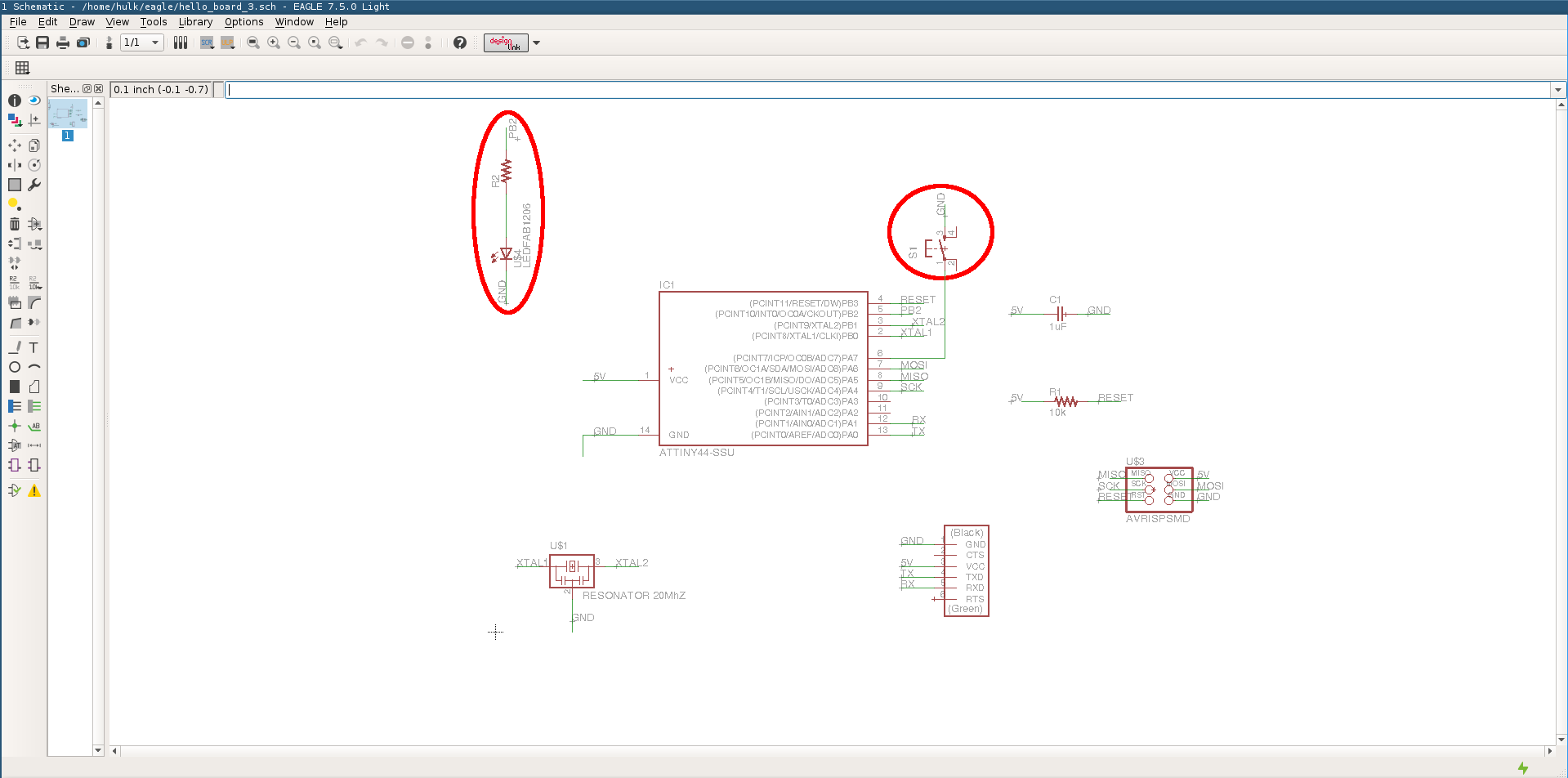
After i've learned the basics,i've started to design the echo hello board starting from Neil's design:
At this point, i've downloaded this eagle library wich contains all the components for the
hello board:
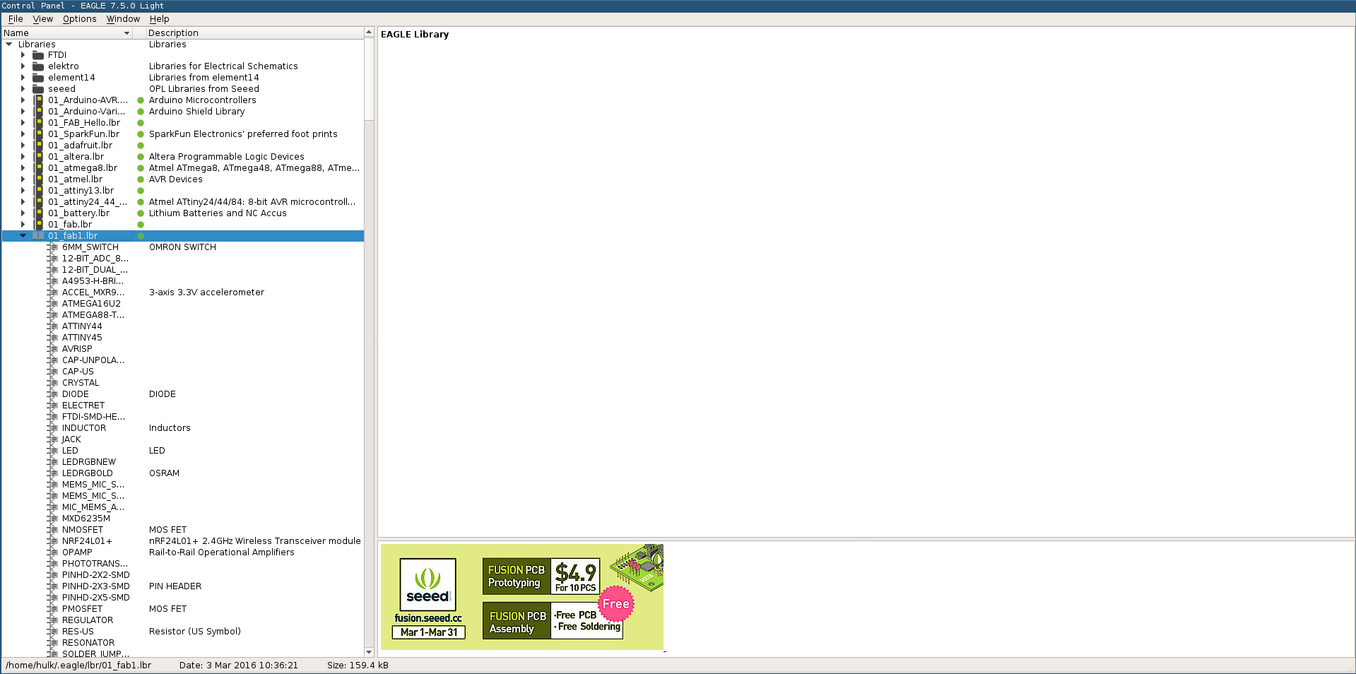
Tip: i've renamed the library as "01_fab.lbr". In this way the library is on top of the list
in the library archive inside eagle.
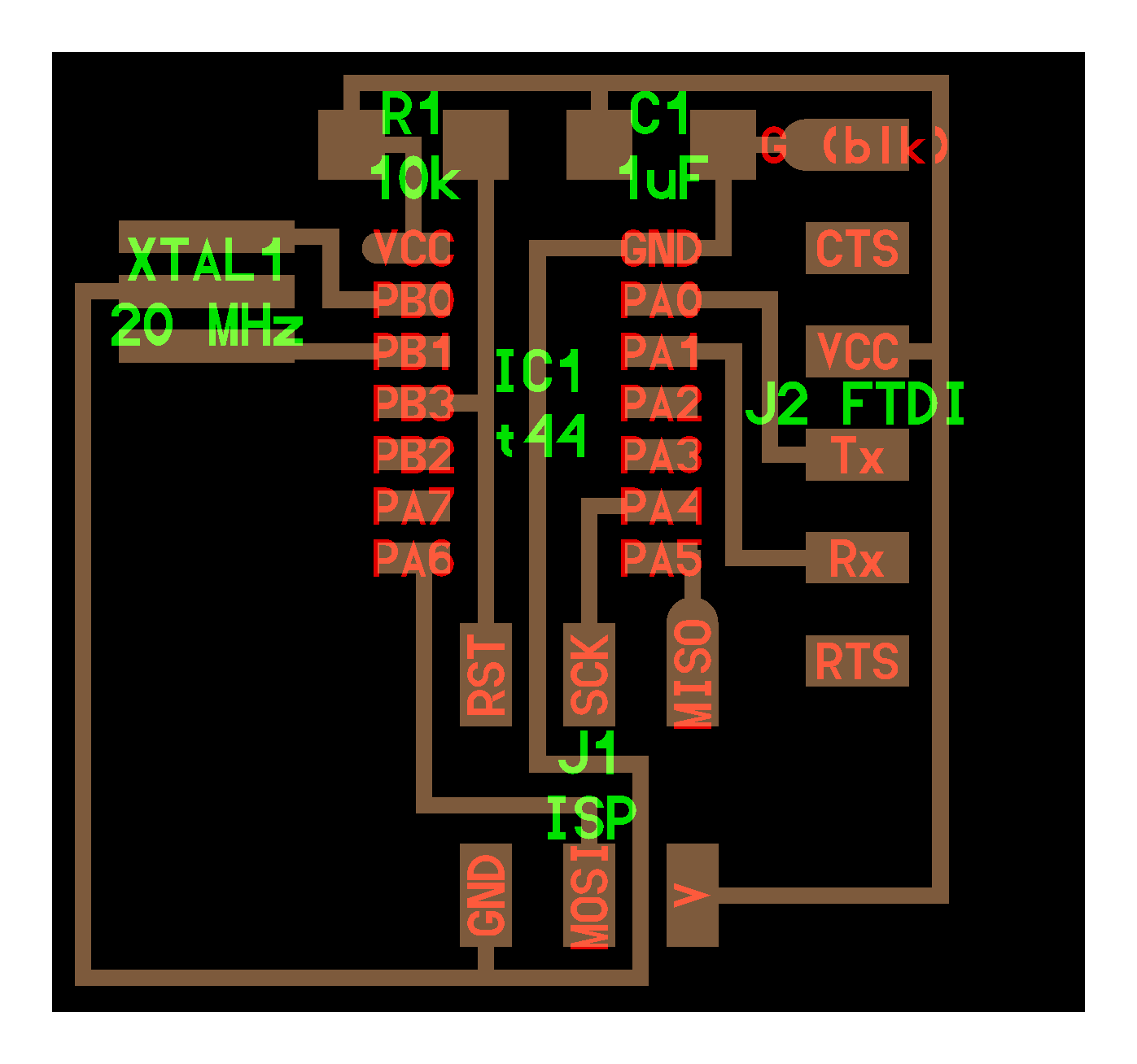
I've first placed all the components which are in Neil's hello board and then i've added the net for
the button and for the LED:
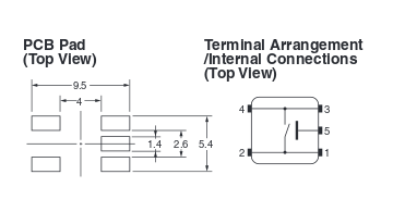
I was not sure on how to position the button so i've checked the datasheet of the component to
find the answer...
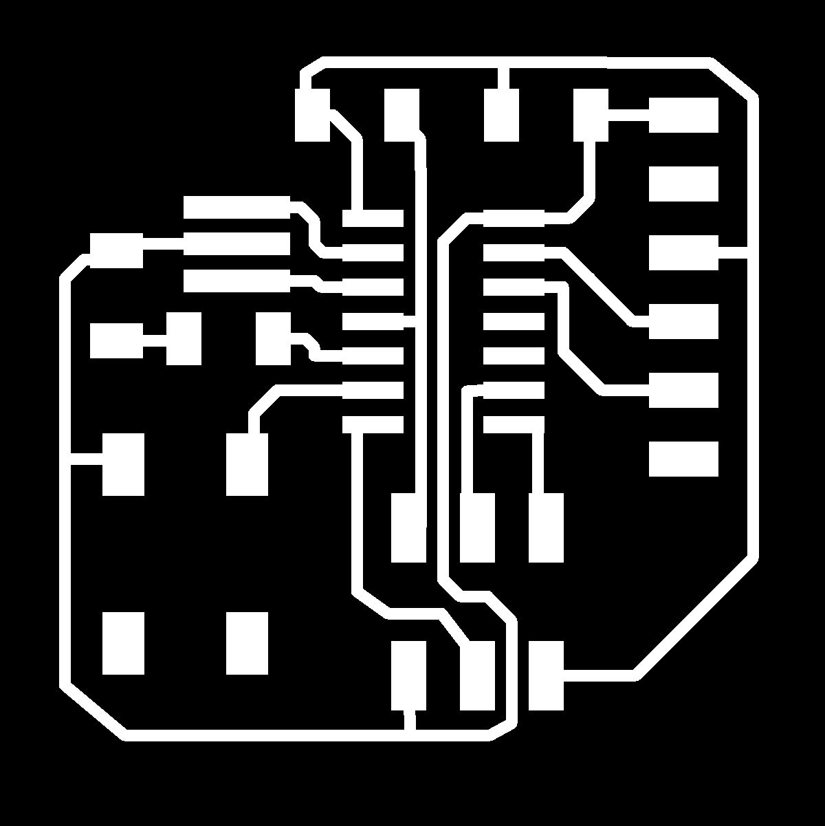
After i've finished the schematic, i've started to build the traces of the board and this is
the board:
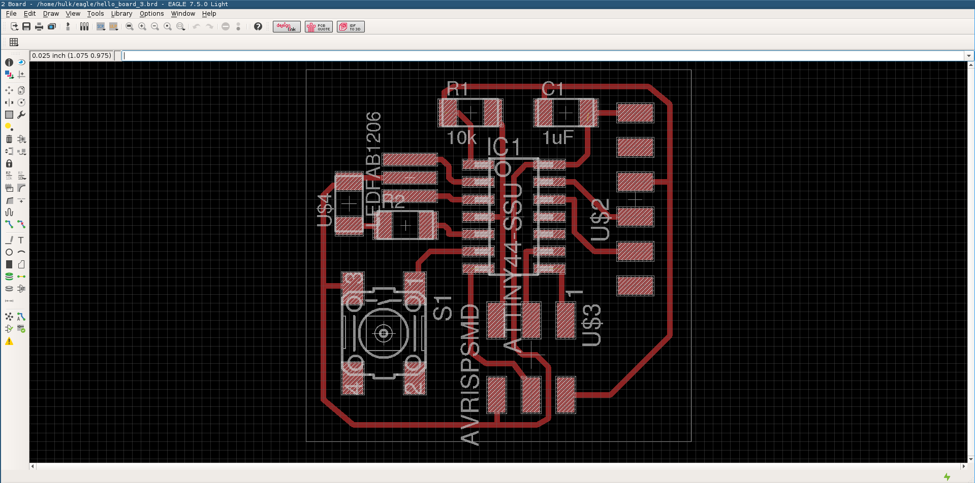
Here the files (SCHEMATIC - BOARD)
Before exporting the .png for the traces, i've defined and checked the design rules through the DRC
tool integrated in Eagle (from Tools-->DRC).
Theese are my design rules:
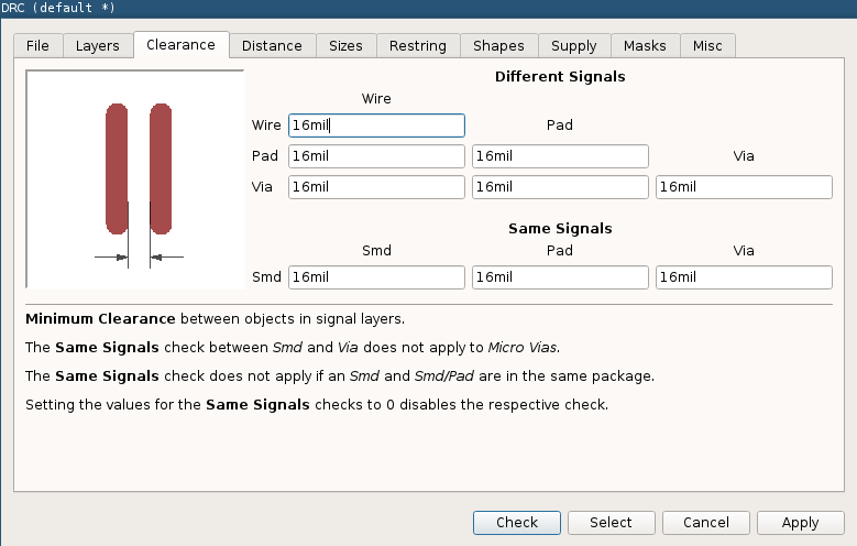
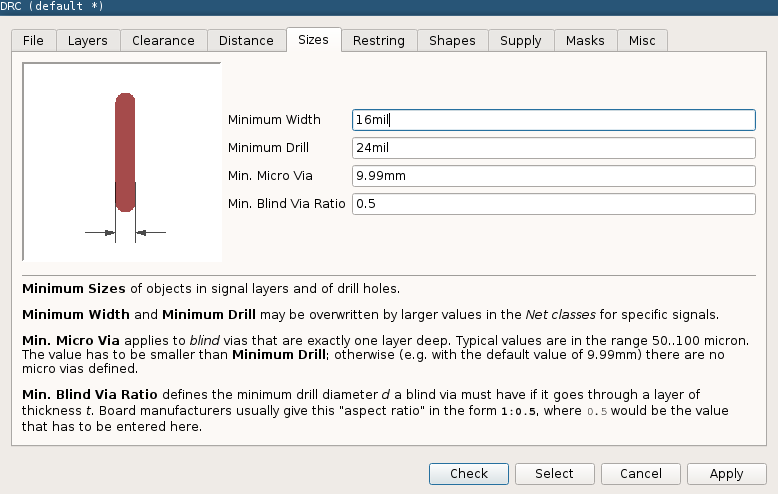
I've recieved only "Stopmask" error which are not relevant for the milling process:
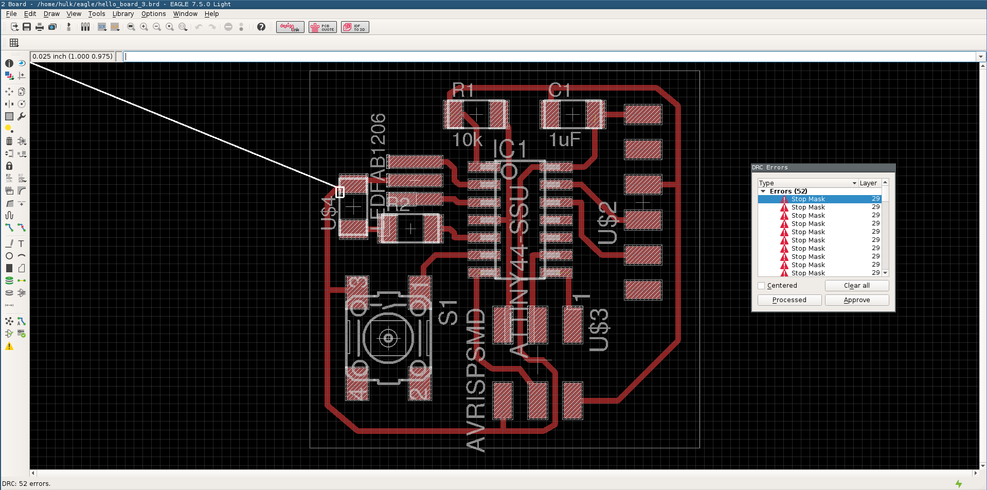
At this point i've exported the file to gimp following this
procedure (section "Exporting a Board Design to be Used with Modela").
Here are the files (TRACES - OUTLINE)
At this point, i've used the fabmodules as i've already described here
to generate the .rml files to mill with the Roland SRM20 (ETCHING - CUTTING).
The following table is the BOM for the hello board:
| Code | Description | Quantity |
| 223-2394 | 10Kohm resistor | x1 |
| 223-2265 | 1Kohm resistor | x1 |
| 696-2513 | ATtiny 44 microcontroller | x1 |
| 766-1062 | 1μF capacitor | x1 |
| 682-1406 | Button | x1 |
| xxx-xxxx | 20Mhz resonator | x1 |
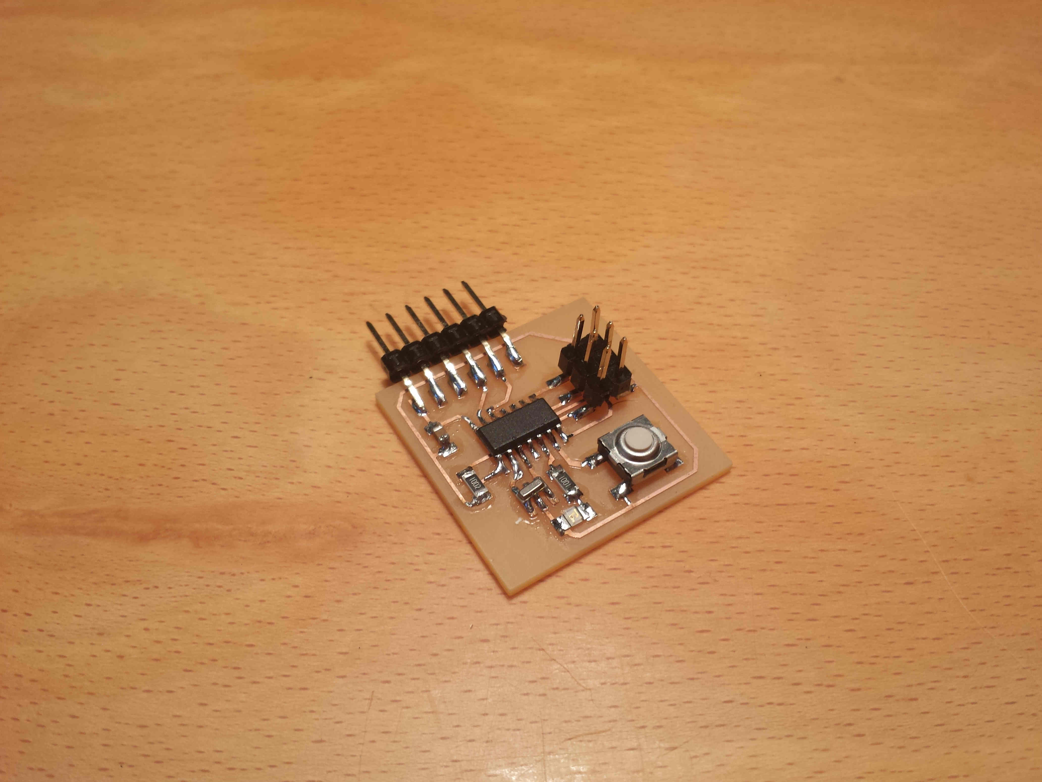
And finally, this is my hello board:
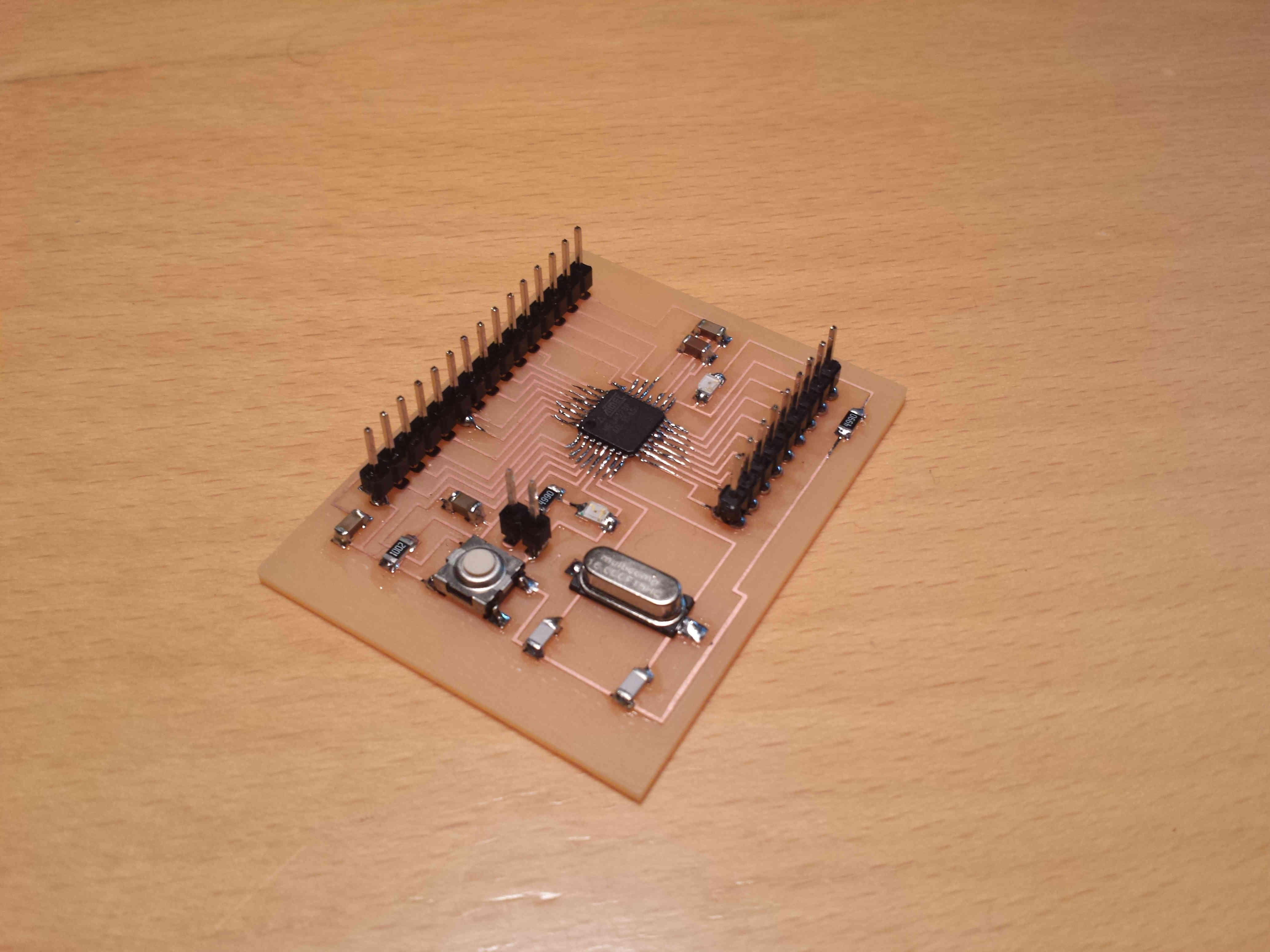
Following the same procedure described above, i've also made the satshakit.
I've simply cloned the github repository and i've found all the information needed for the kit inside the archive stuff.
Here is the BOM for the kit (DOWNLOAD) that i've downloaded directly from the GitHub repository of the satsha kit and this is the resulting board:
Programming & Testing
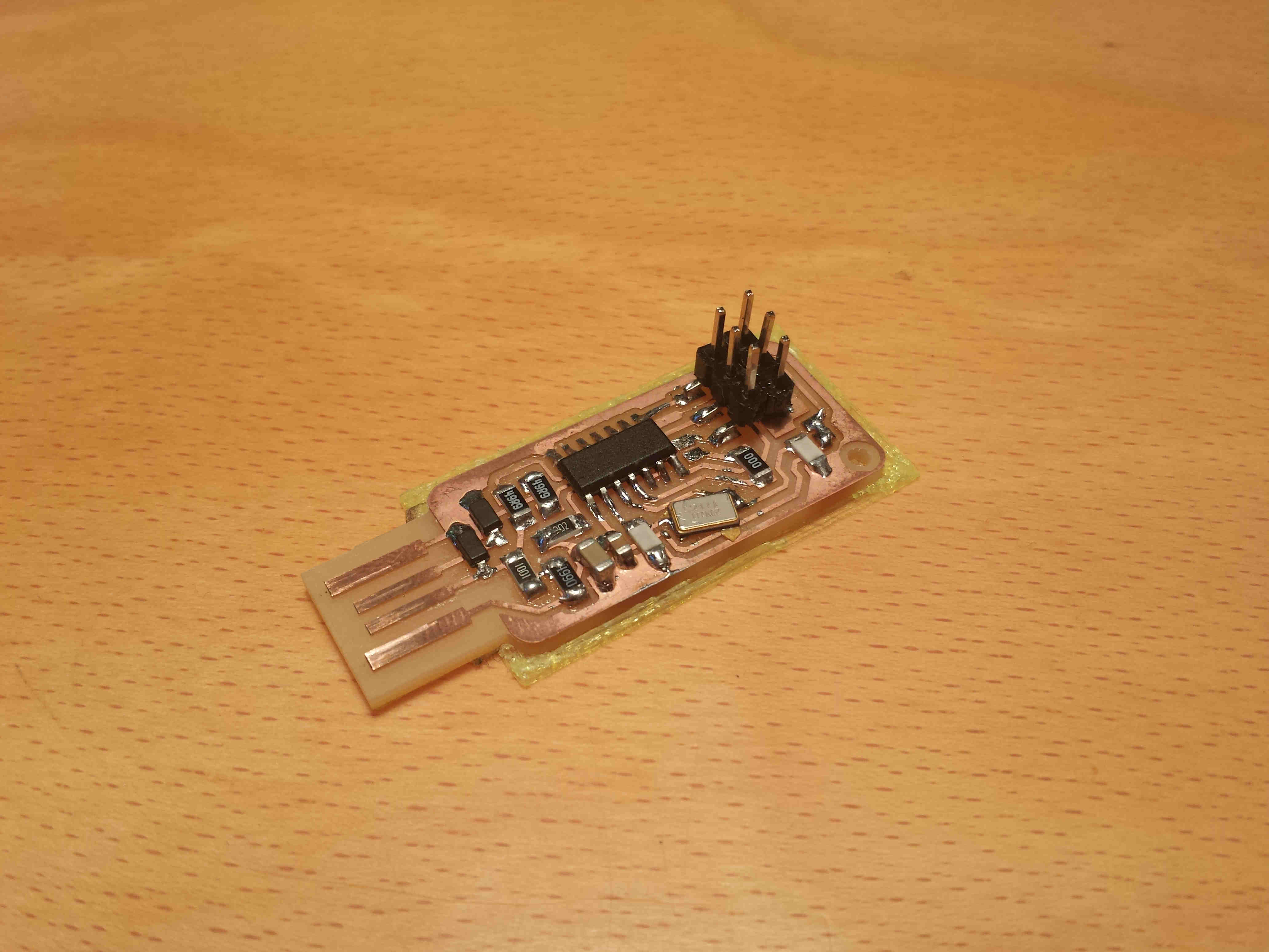
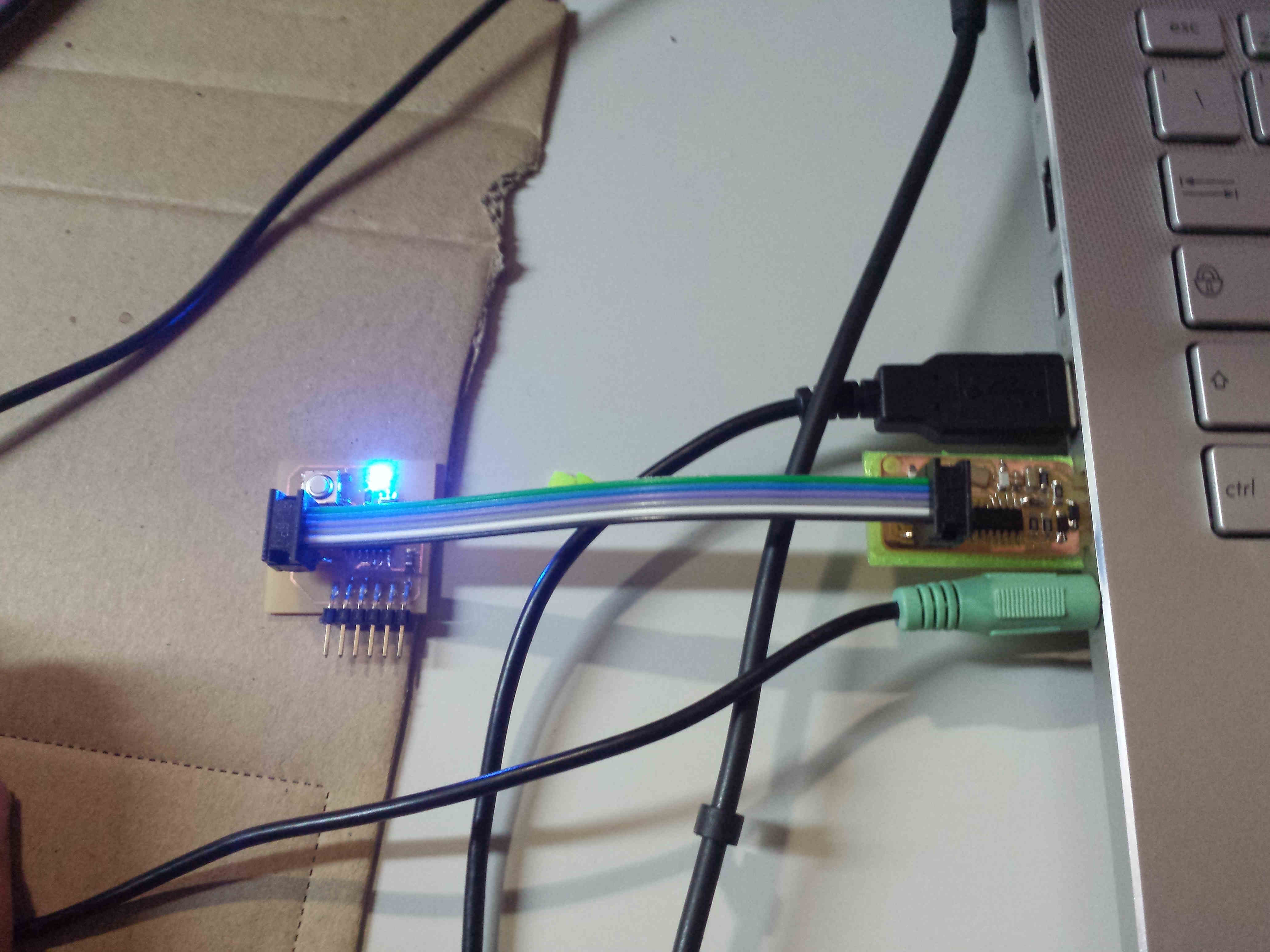
To program the hello board i've used the FabISP board builded in week4.
First of all i've downloaded the hello.ftdi.44.echo.c and
hello.ftdi.44.echo.c.make files to program the hello board.
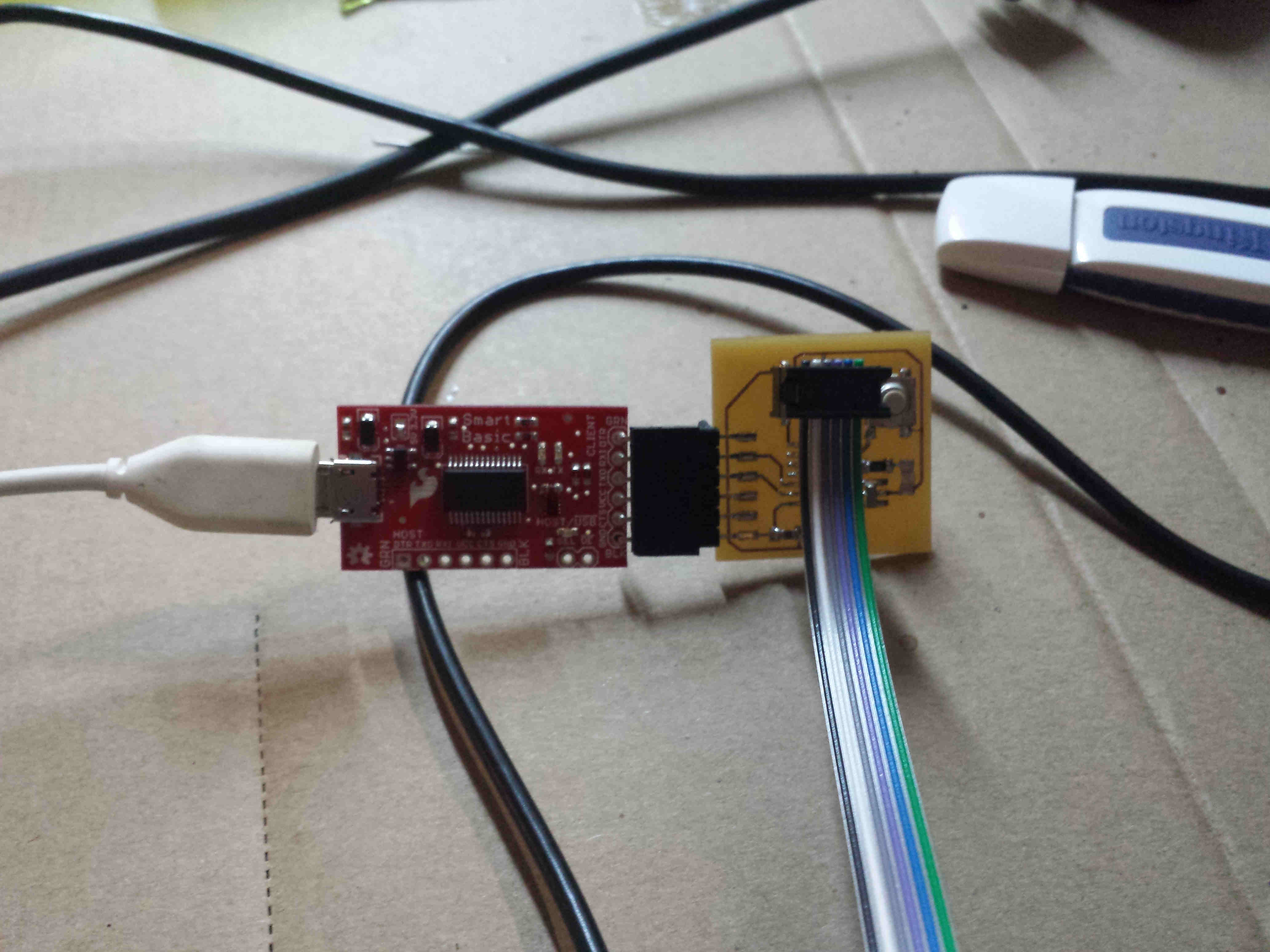
Then i've connected the two boards as shown in the picture below:
CONNECTIONS-IMG
and i've executed this set of instructions (from the folder containing the files):
and the corresponding output:
make -f hello.ftdi.44.echo.c.make
sudo make -f hello.ftdi.44.echo.c.make program-usbtiny-fuses
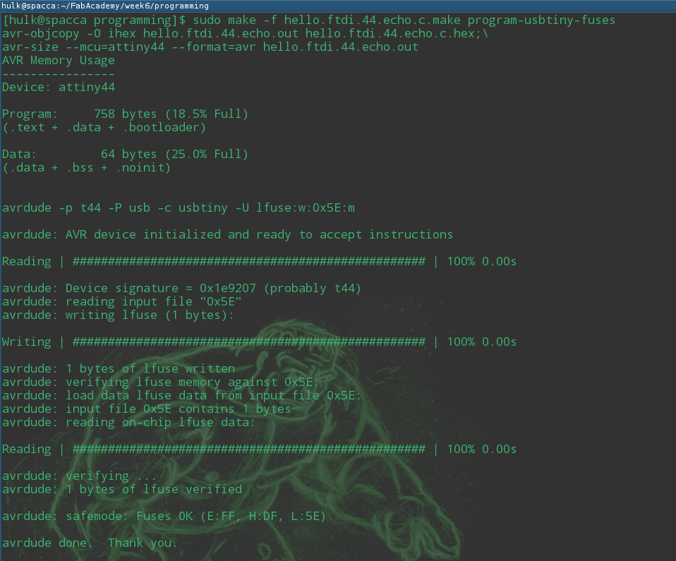
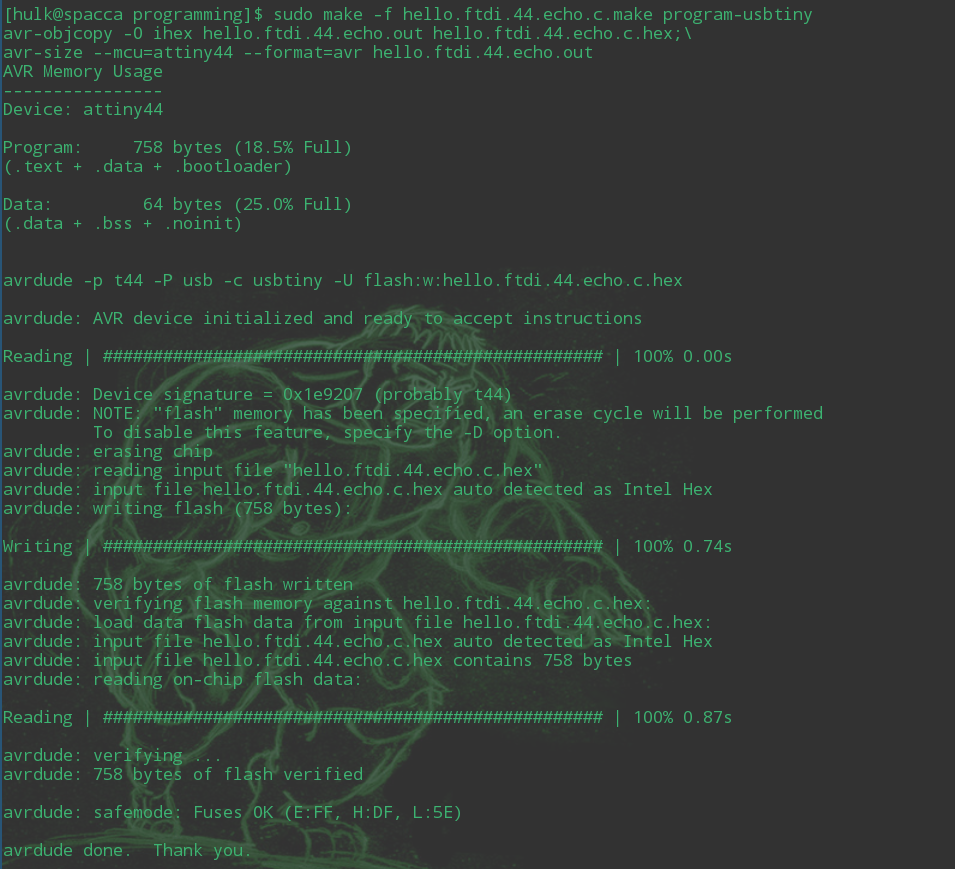
then:
sudo make -f hello.ftdi.44.echo.c.make program-usbtiny
with output:
At this point i wanted to check if everything went fine so i've decided to run this
python program found on the schedule page.
I've got some bad-indendation errors when I tried to run the program so i've modified the code
and here you can download the working version (DOWNLOAD).
Note:the version of python that i've used to run the script is the 2.7
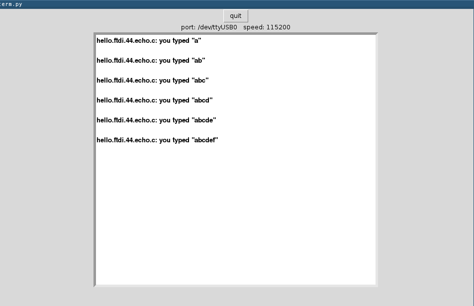
After editing the script, i was able toccomunicate via an FTDI connector with the computer.
By running:
python2.7 term.py /dev/ttyUSB0 115200
I've obtained a "talking" board:
Once obtained a working hello board, i've tried to write a little program in C to test at least
the LED on the board. I've modified the hello.ftdi.c.make file to work with my program (LED.MAKE - LED.C)
Following the same procedure described above:
make -f led.c.make
sudo make -f led.c.make program-usbtiny-fuses
sudo make -f led.c.make program-usbtiny
Here the result:
Once completed the hello board i've started with the satsha board.
I've tried first to flash the arduino bootloader through my FabISP but after
wiring up the boards as hown here:
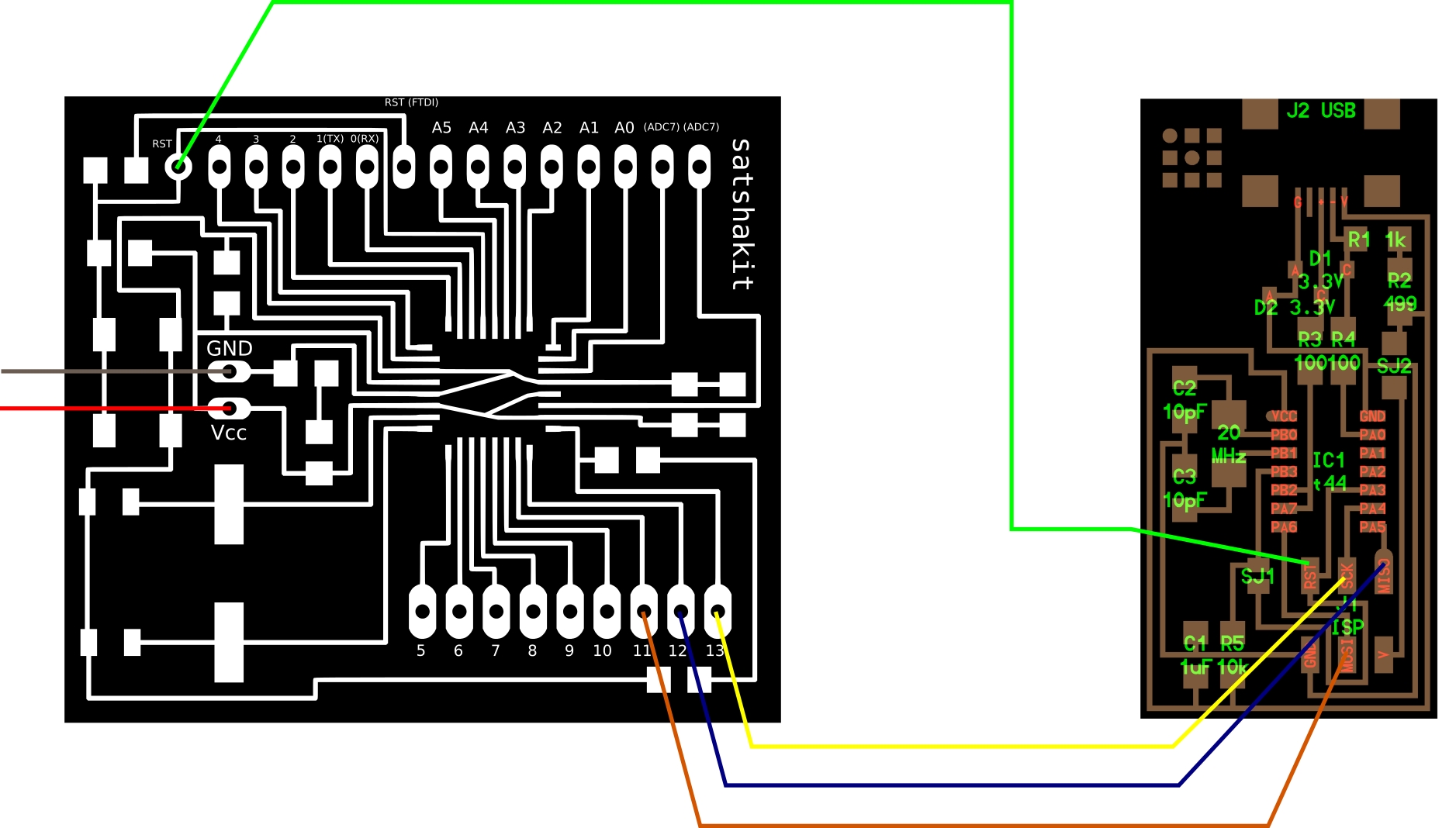
I've got the "not-in-sync" error from the Arduino IDE when i've tried to burn the Arduino bootloader on my
satsha board.
I've then checked all the connections of my FabISP and nothing seemed to be wrong. To have a final proof of the fact
that the board was not broken, i've tried to program another FabISP and it worked.
At this point I decided to try to flash the bootloader through Arduino:
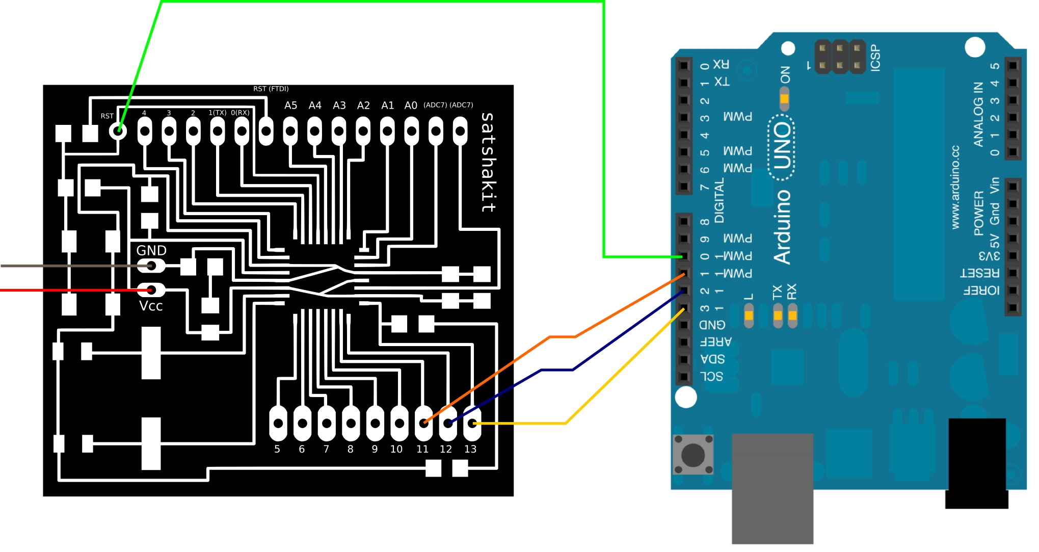
I've loaded the "Arduino as ISP" sketch on the arduino (it is located inside the Arduino Example folder) and
then, from Tools --> Programmer, i've selected "Arduino as ISP".
Then i've wired the two boards:
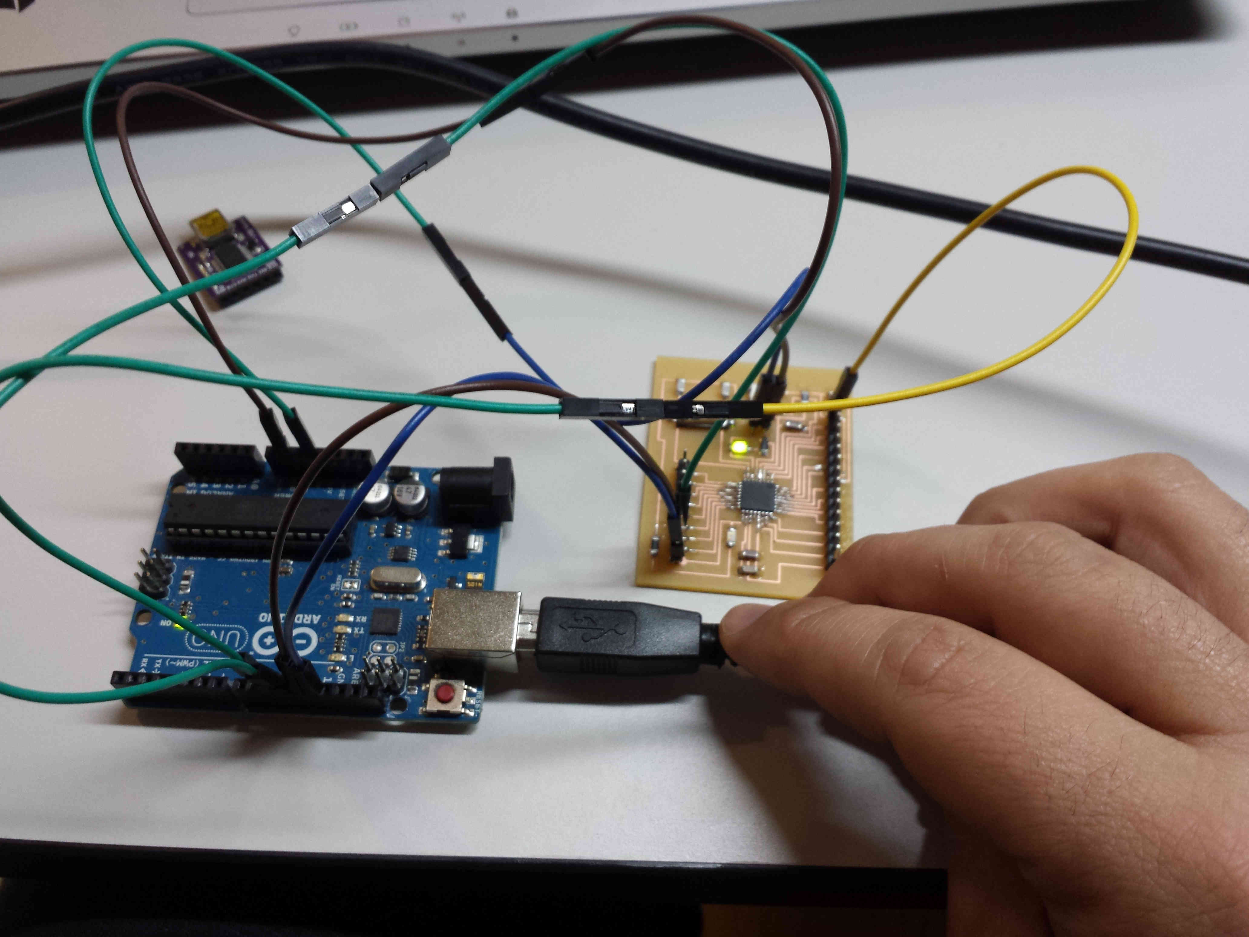
And then from the Arduino IDE Tools --> Burn bootloader.
Right after I've flashed the bootloader I wanted to upload an example sketch from Arduino IDE to check
if everything was ok.
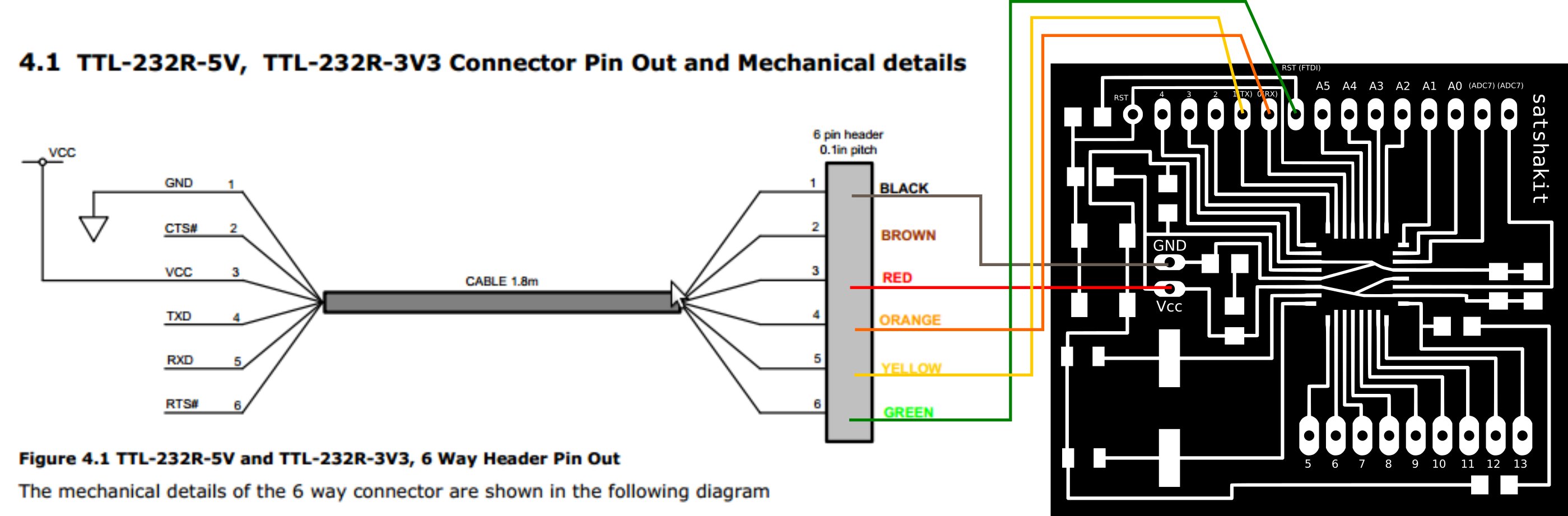
I've tried first to disconnect the board from the Arduino and to use an FTDI board. I've wired the two boards
as described in the satsha how to on the repository:
But when I've tried to upload the "Blink" example sketch from the Arduino IDE i've got again the avrdude not in sync
error from the IDE.
After a couples of tries, again I've tried to use arduino as ISP and to upload the sketch from the IDE.
This time works:
Conclusions
Understanding how to build a board from scratch is a process that i find really fascinating. I've a previous
knowledge in electronics from my universitary studies but i've never had the opportunity to develop the entire
design process of a PCB. Moreover i found really interesting the fact that, by knowing how to use such tools,
is possible to realize an arduino-like board for less than a half of the price and with nearly the same funcionality.
I want to investigate more the process and to learn how to do more sophisticated boards ad i'm curious to investigate
the programming part.