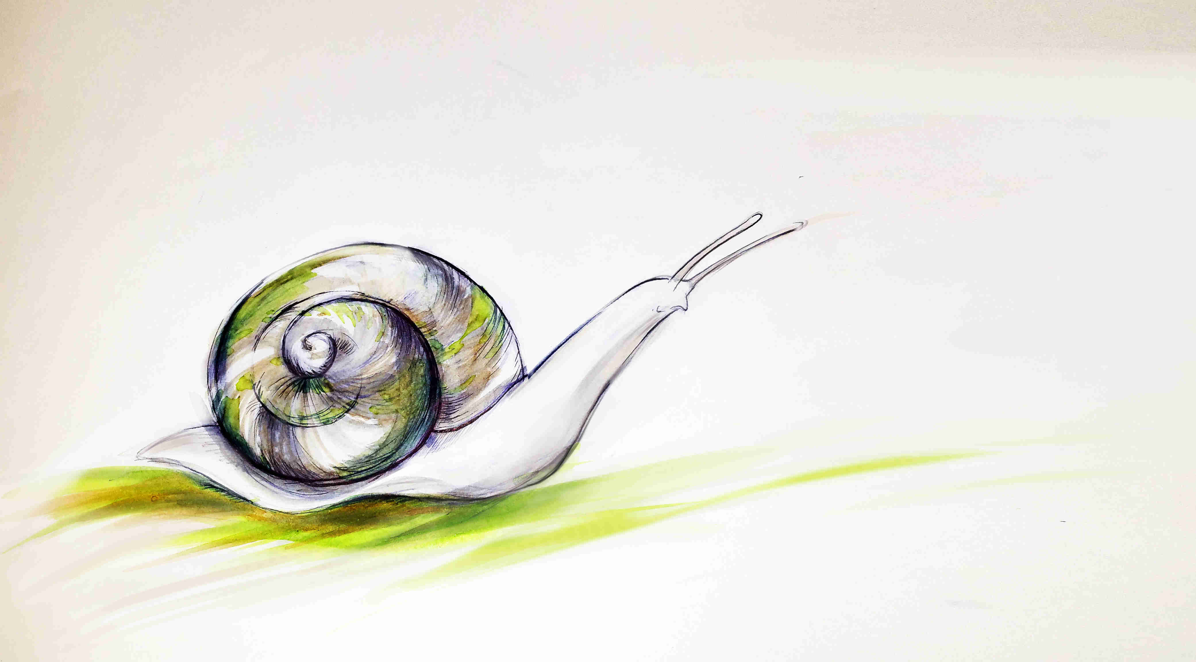
She really likes walking during rainy ugly days...
But she does not like to walk on dirty and dry grounds...
To be honest, Fab Snail does not like many things...like polluted air or muggy days...
She is not the only one who doesn't like all that, just like all the other snails...
The difference is that if Fab Snails is not happy, she can turns into a real stalker!
(Also on your mobile -.-)
So take care of Fab Snail, she is a good snail...
She is just different from the other snails!"
Weekly Assignment
The weekly assignment was:
- Complete your final project, tracking your progress:
Process
To build my final project, i've tried to use the greatest number possible of processes that i've
learned during the whole FabAcademy. Actually i've used the following processes to develop different parts of the
project:
- 3D design and printing
- Electronic design and production
- Networking
- Input device
- Output device
- Embedded programming
- Interface programming
3D design and printing
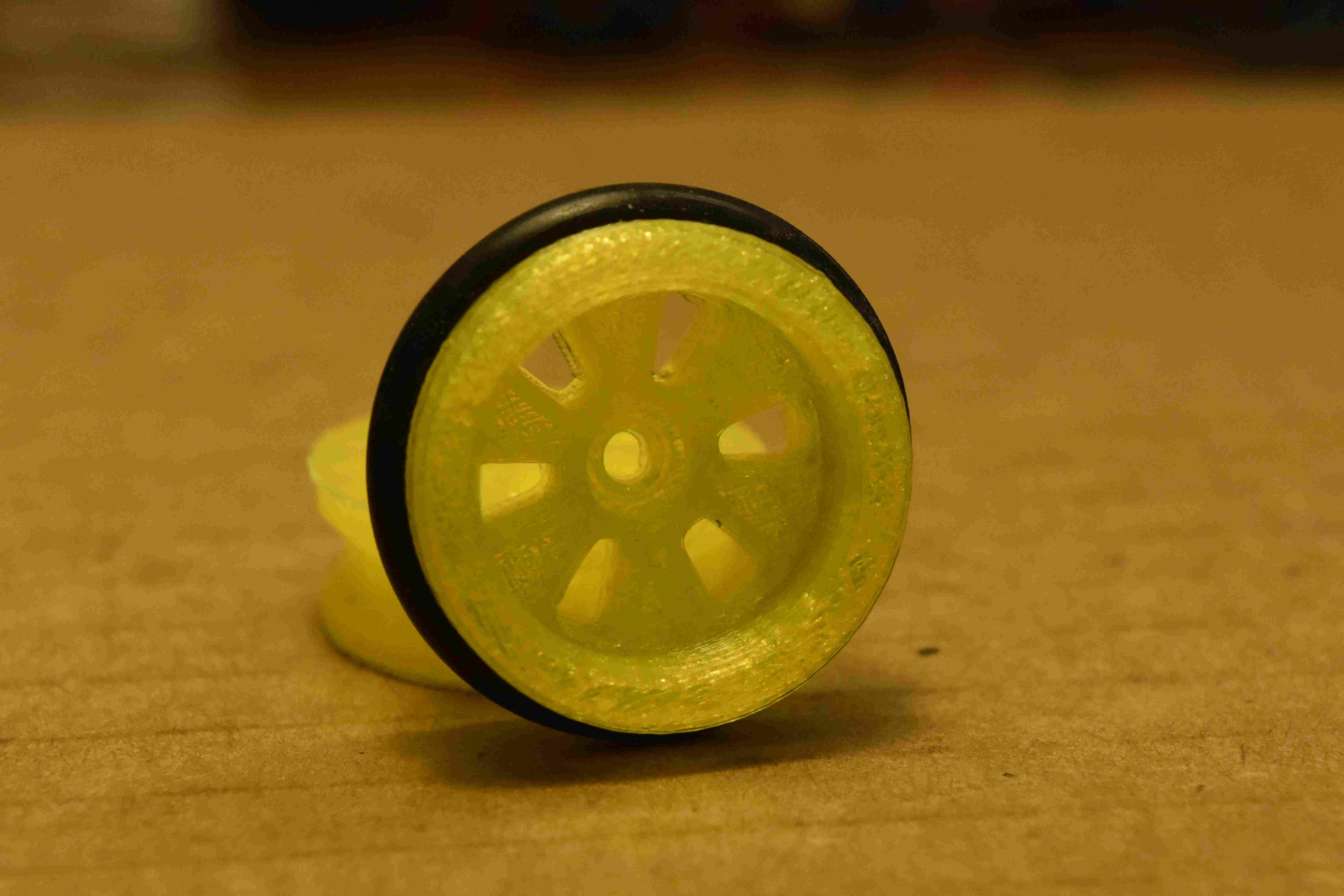
I've used Solid Works to design the wheels and the frame of the Snail. The following are the final models that i've used to build the robot (DOWNLOAD wheel - track - frame).
I was not able to design the shell using SolidWorks so i've used Rhinoceros (see week5 - 3D scanning and printing for more info) (DOWNLOAD Shell).
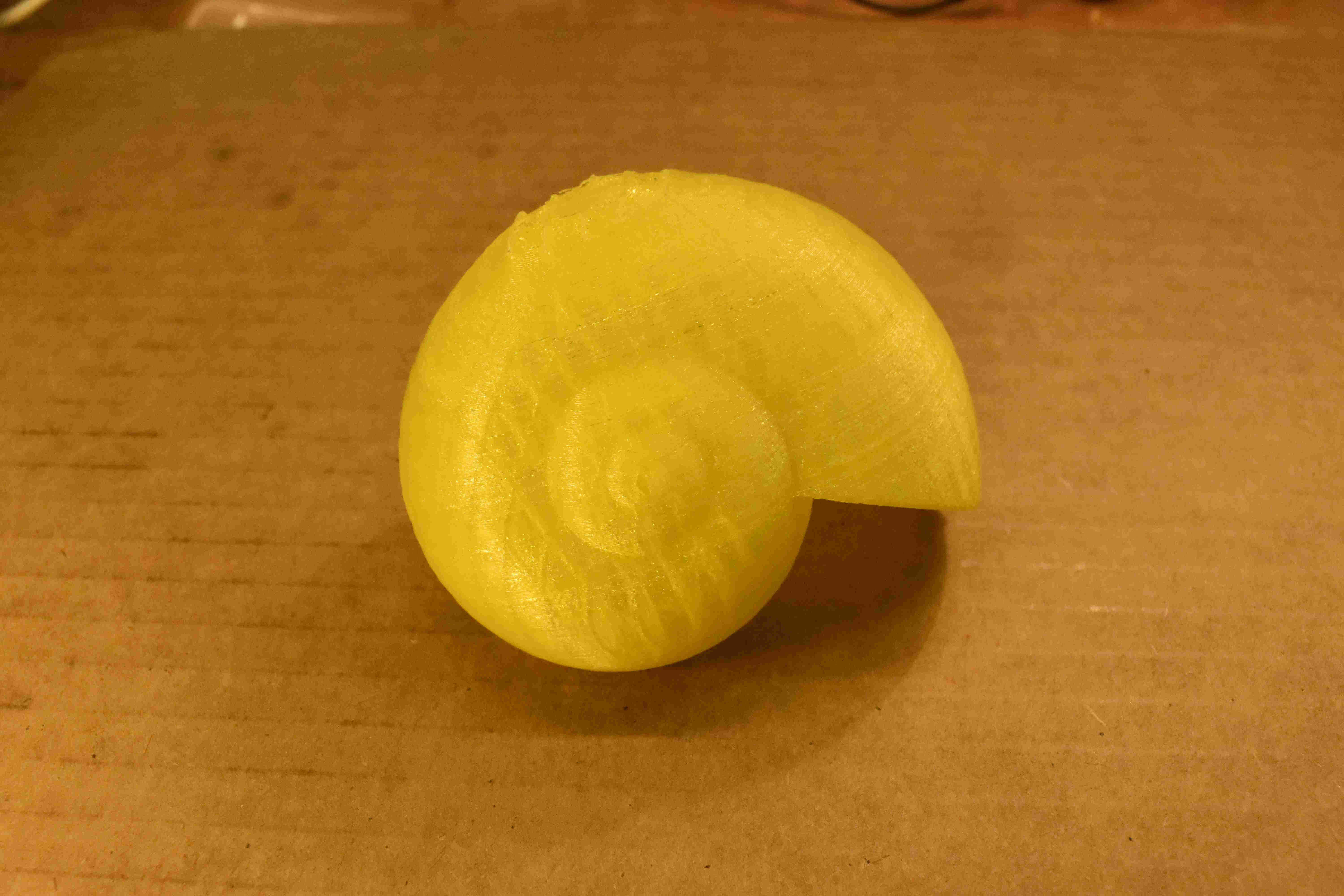
I've used also blender to make a boolean operation on the stl of the shell to make an holed of the dimension of the electronic board that hold
the electronic part of the project.
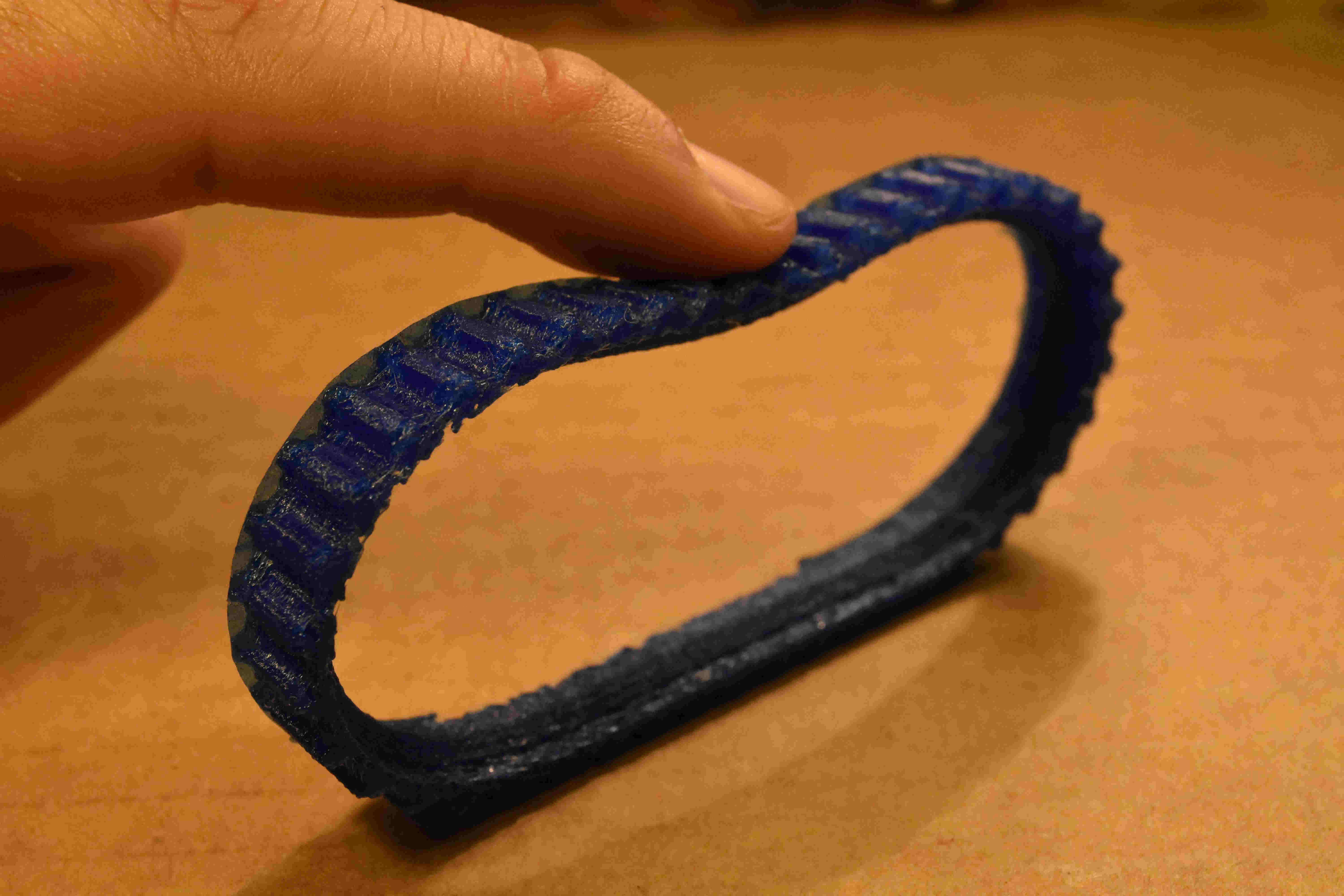
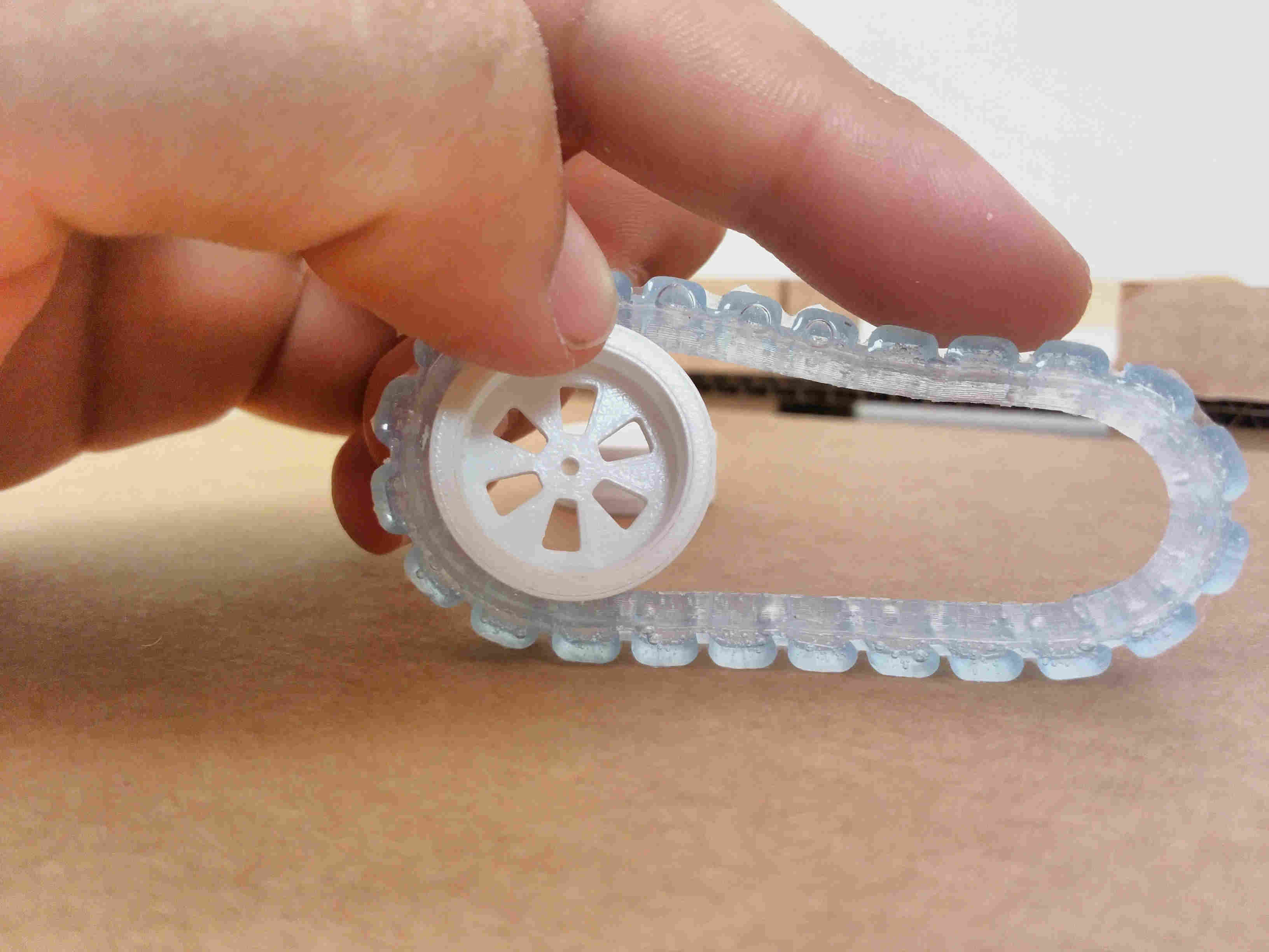
I've used PLA to print the wheels, the frame and the shell while i've used NinjaFlex filament (a rubber-like filament) to print the track.
I'm still not using the track because is really difficult to put it in tension between the wheels but i'm planning to use it in the final
project.
Electronic Design and production
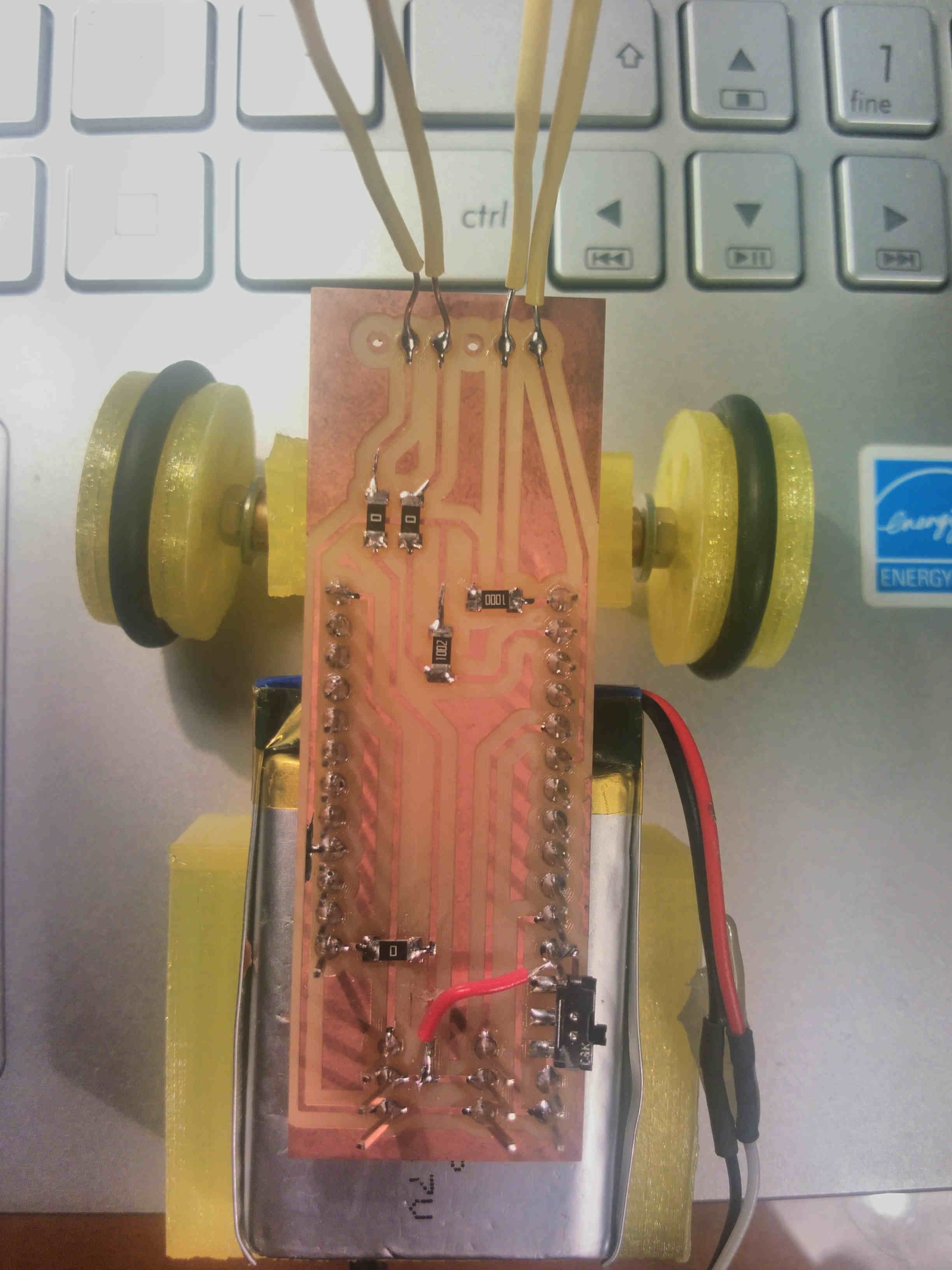
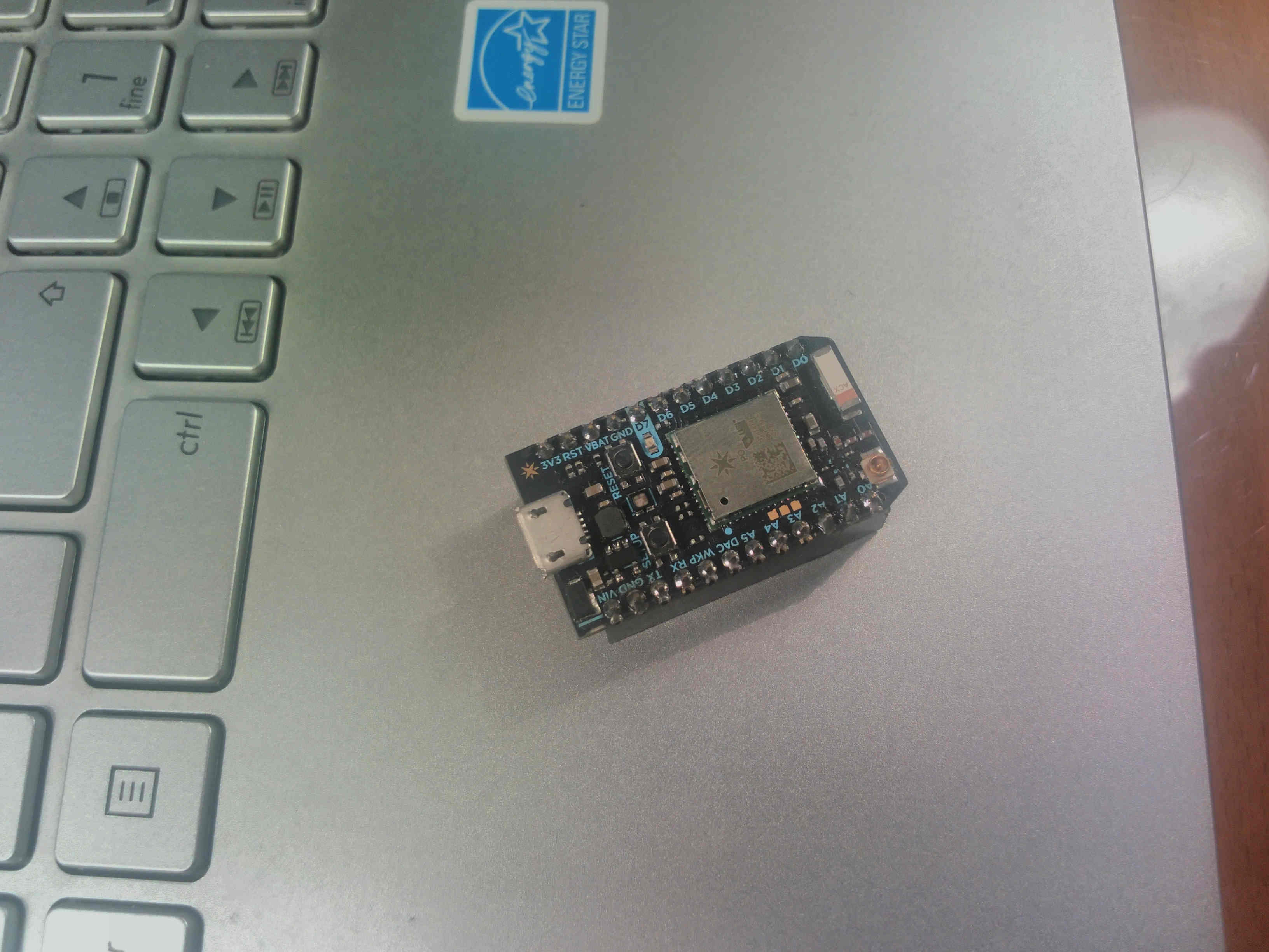
I've used a Particle Photon board for my final project.
It is supposed to cost $19 but my instructor Fiore stole it during a faire so i've stolen
it from him.
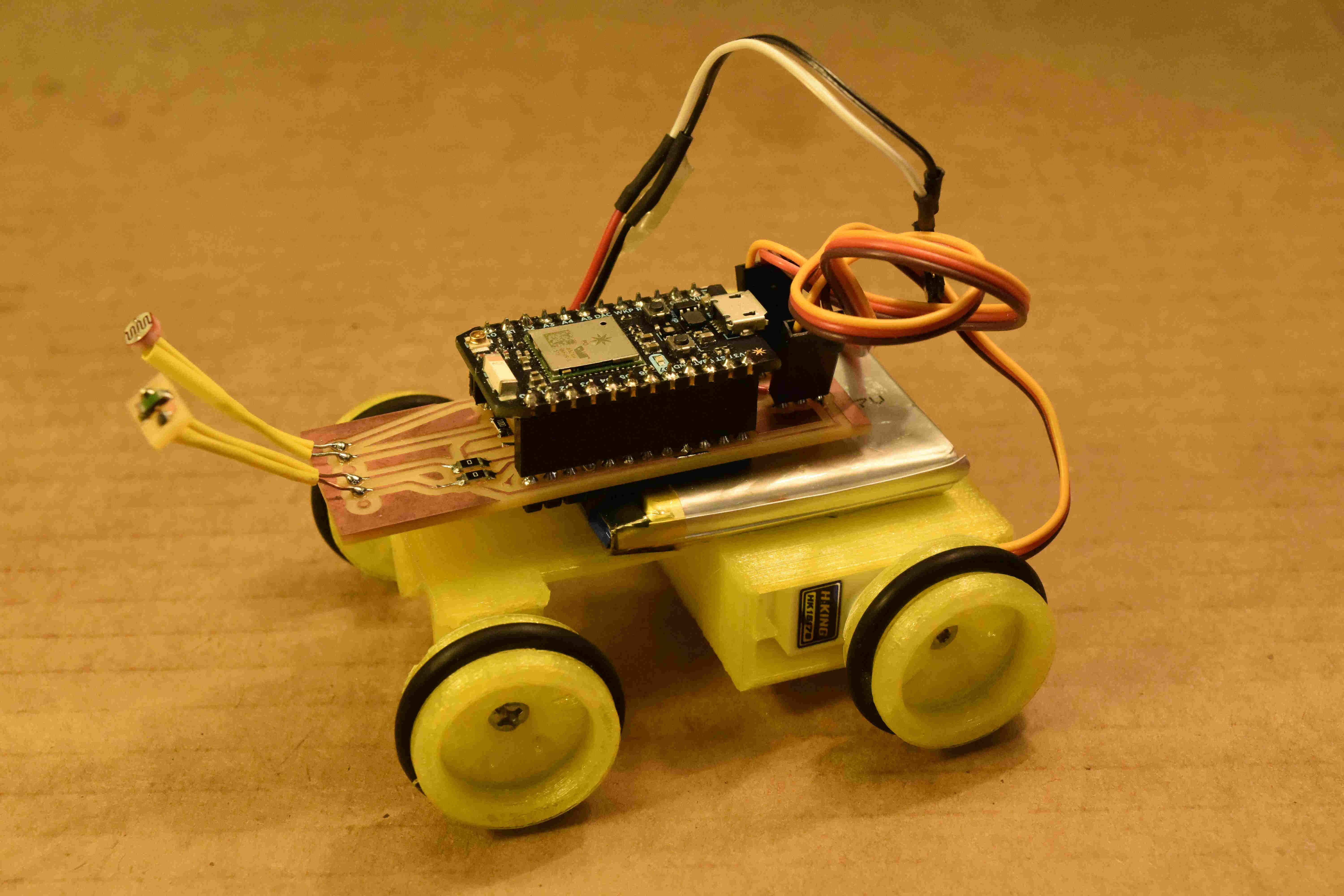
I've then builded a brackout board to integrate the photon with the circuit needed to read two sensors,a photoresistor and a thermistor,
with a switch to power on and off the board and with two connectors for two servomotors. I've also realized a very small piece of PCB for the smd thermistor. (DOWNLOAD photon.sch - photon.brd,
therm_adaptor.brd):
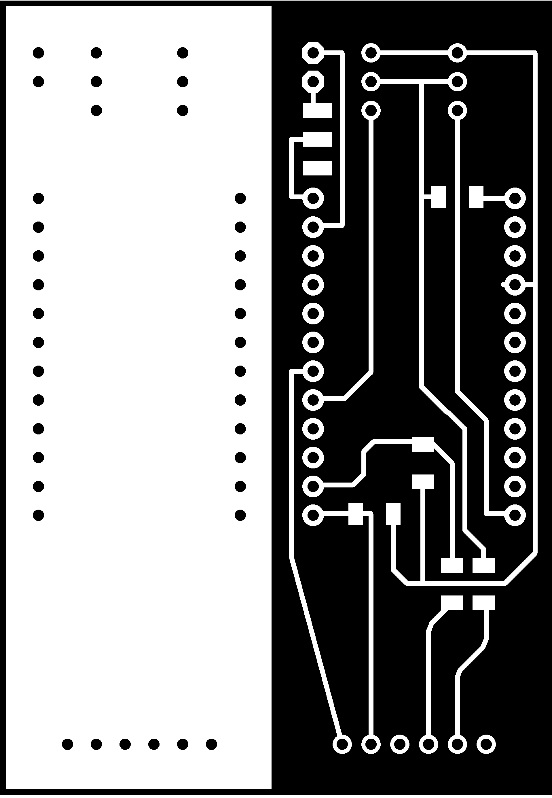
I've found that taking the power from the Vin pin of the photon instead that from the 3v3 pin, can result in continuos resets if you have other
components that absorbs electricity (in my case i had two servomotors).
This is the final result:
Networking
As said, i've used the Particle Photon board. This board, has an integrated WiFi and uses a cloud siystem for handling the data.
The documentation is really well written and this result
in an easy-to-use system. To be short, is possible to connect the board to any network and to publish variables and functions over the cloud.
The board has a unique address and a token which can be used to retrieve data and to identify it.
There are two IDEs, one online and one offline and is possible to write firmware and upload that to the board via WiFi.
I will describe better what i've done with the board in the next paragraphs but for now, i want to highlight the fact that
i've decided to integrated a WiFi based board to have more flexibility in the project and to control the funcionalities of the Snail
withouth the need of any cables.
Input Devices
I've used two sensors as input devices, a photoresistor and a thermistor. As explained here
and here, i've already used this two sensors during
the previous weeks of FabAcademy and i've decided to include them in my final project. Trying to be creative, i've soldered this sensor
on my board in a way that they can look like the antennas of the Snail:
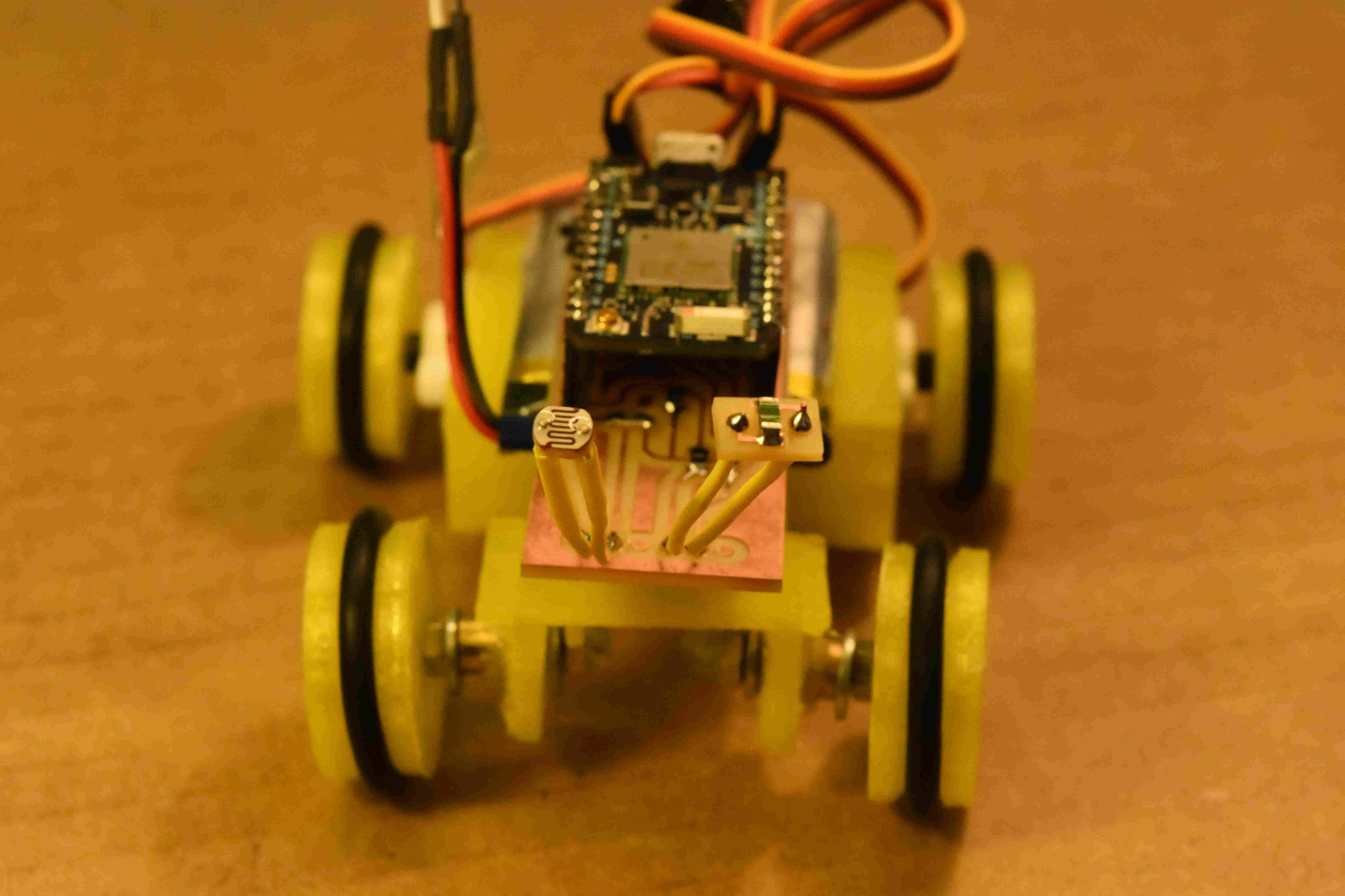
Output Devices
I've used the two servomotors as output devices. I can control them directly from the web and i can move them separately.
In this way i can control the turning of the Snail; if i have to turn the robot left, i simply spin the right motor forward
and the left motor backward (and the other way around if i have to turn it right).
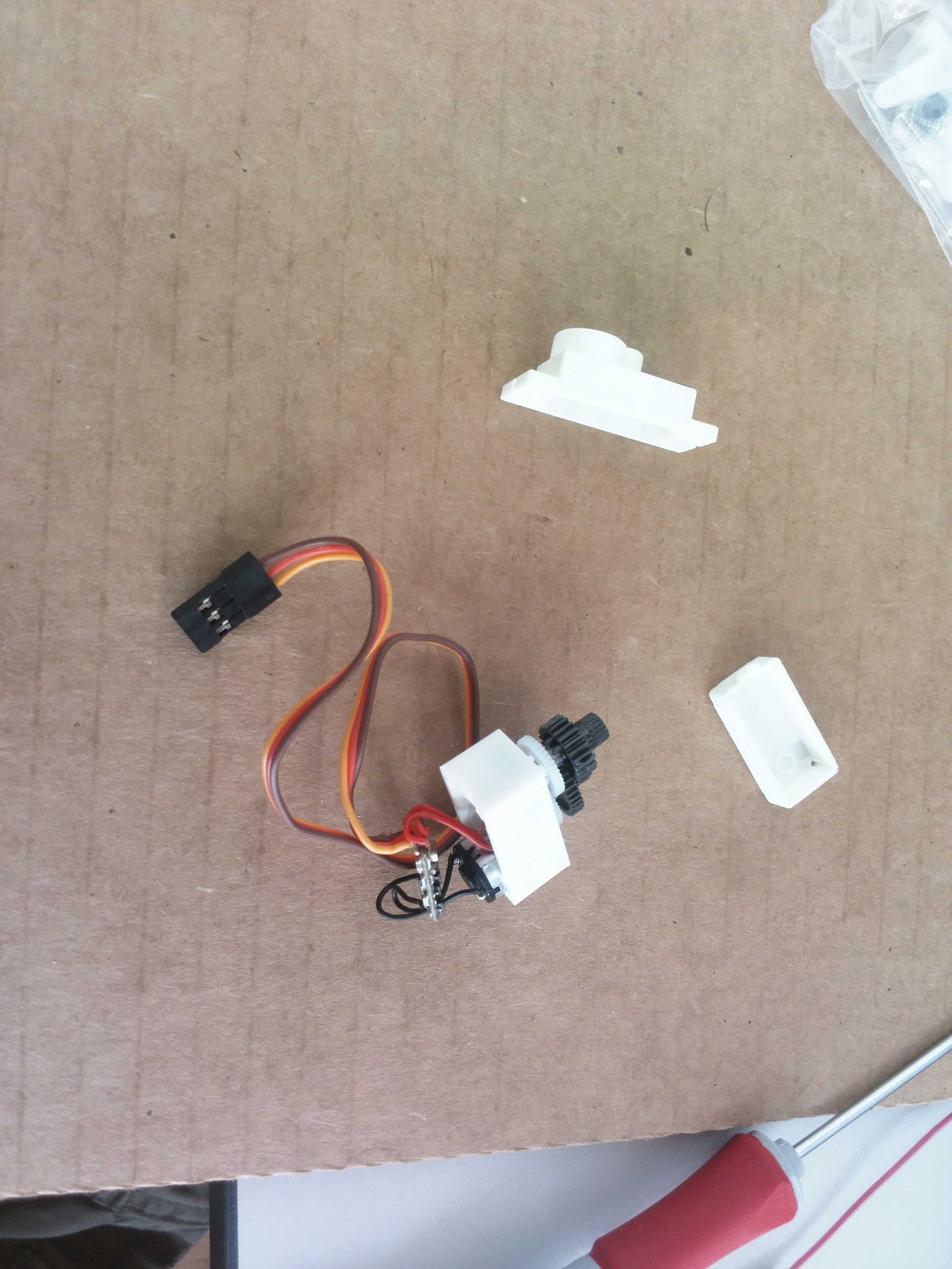
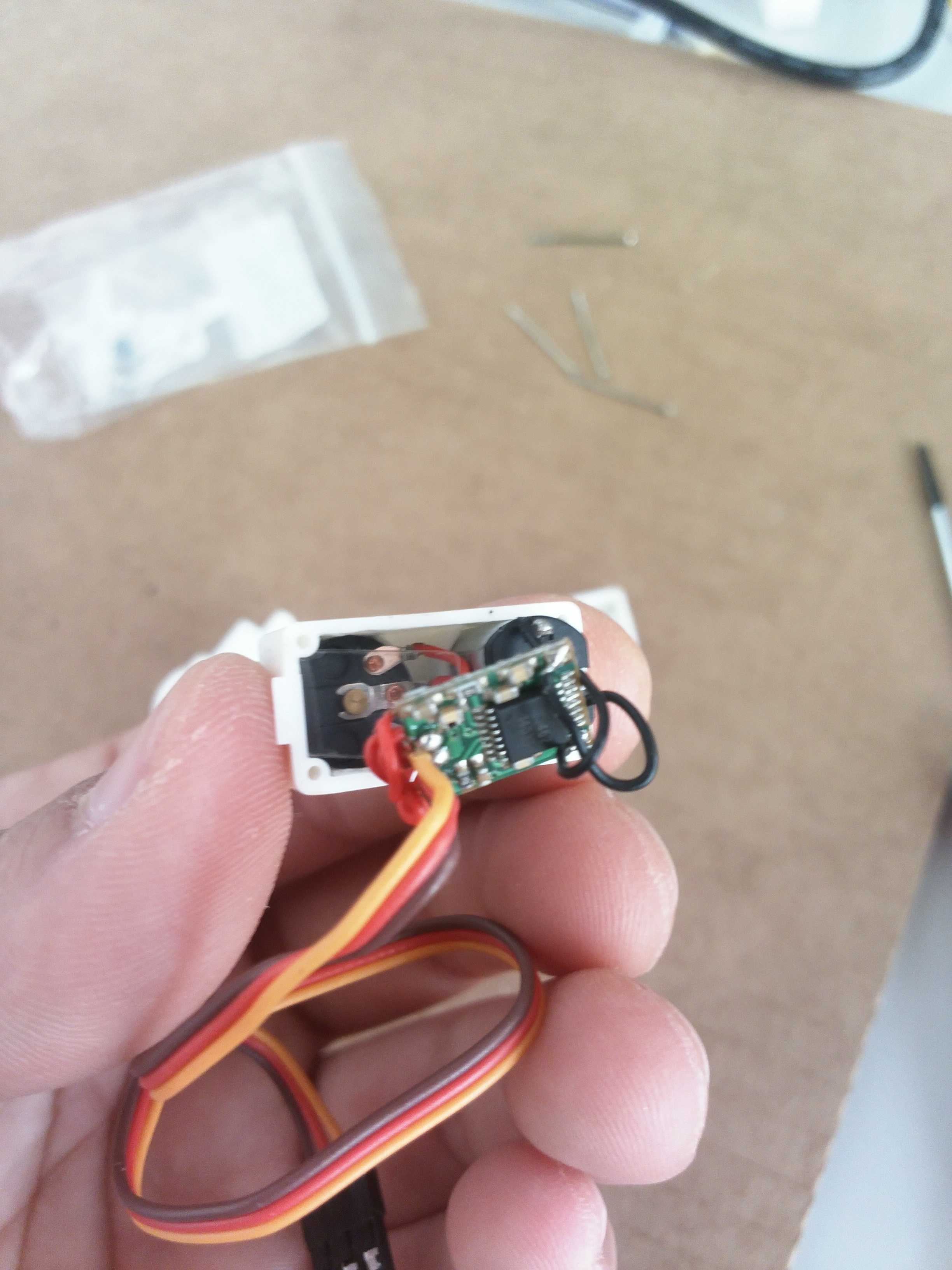
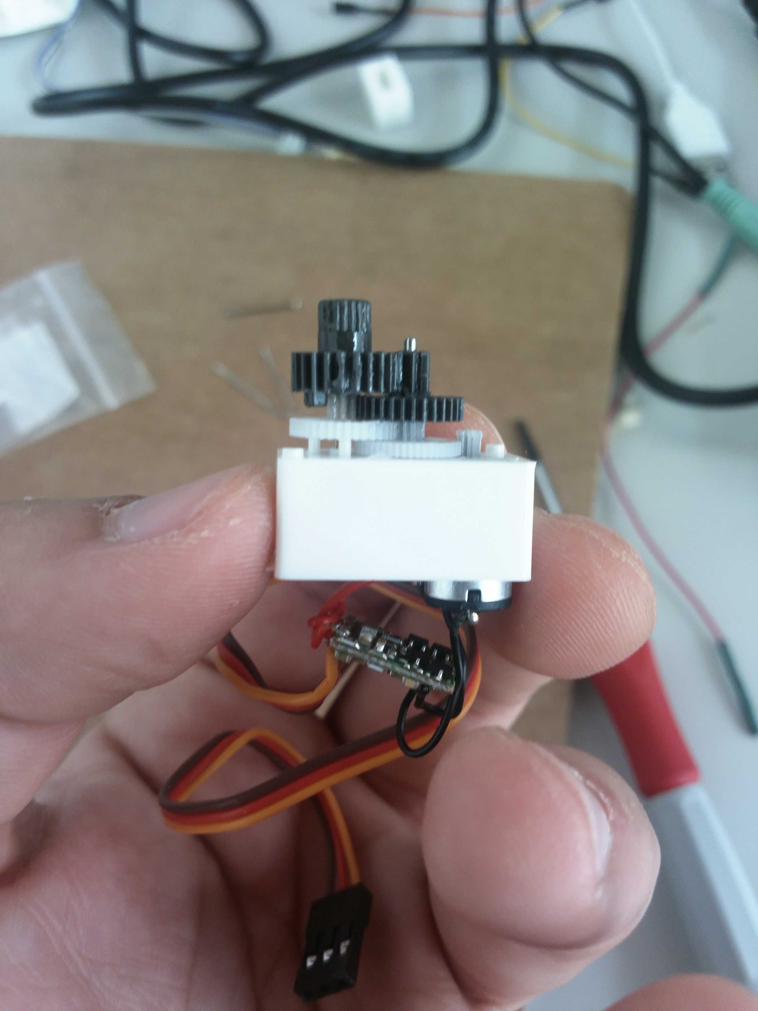
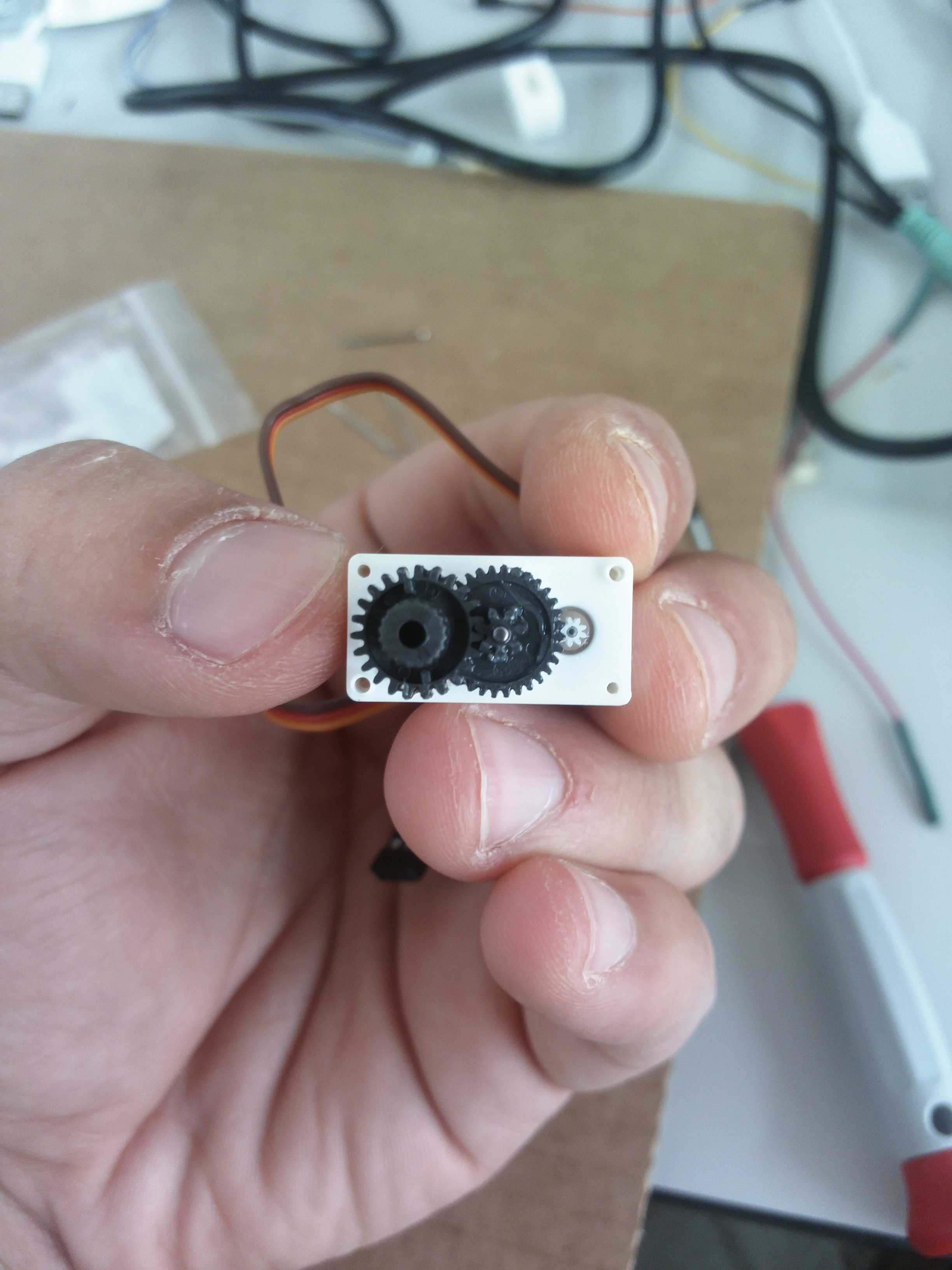
At the beginning, i wanted to use two continuos rotation servomotors but i did not have this kind of motors in the Lab. I've
then decided to modify two normal servos that are in the inventory. There are 10000 tutorials everywhere that explain how to
easily modify a servomotor:
Embedded Programming
To program the particle, i've used the ParticleDev IDE and this is the firmware that i wrote.
#include <math.h>
Servo myservoL;
Servo myservoR;

int led = D7; // This is where your LED is plugged in. The other side goes to a resistor connected to GND.

int photoresistor = A0; // This is where your photoresistor is plugged in. The other side goes to the "power" pin (below).
int ThermistorPIN = A1;
int power = A5; // This is the other end of your photoresistor. The other side is plugged into the "photoresistor" pin (above).
// The reason we have plugged one side into an analog pin instead of to "power" is because we want a very steady voltage to be sent to the photoresistor.
// That way, when we read the value from the other side of the photoresistor, we can accurately calculate a voltage drop.

int analogvalue; // Here we are declaring the integer variable analogvalue, which we will use later to store the value of the photoresistor.
int analogvalue2;
float res = 10000; //fixed resistance that i've used for the voltage divider
float resx;  //variable resistance
float logresx;
float T;
float c1 = 1.009249522e-03, c2 = 2.378405444e-04, c3 = 2.019202697e-07;

double voltage;
double temp;


void setup() {


    pinMode(power,OUTPUT); // The pin powering the photoresistor is output (sending out consistent power)

    // write the power of the photoresistor so that we can use this for power.
    digitalWrite(power,HIGH);

    // We are going to declare a Particle.variable() here so that we can access the value of the photoresistor from the cloud.
    Particle.variable("analogvalue", &analogvalue,INT);
    Particle.variable("temp", &temp, DOUBLE);


    // We are also going to declare a Spark.function so that we can turn the LED on and off from the cloud.
    Spark.function("led",ledToggle);
    // This is saying that when we ask the cloud for the function "led", it will employ the function ledToggle() from this app.
    Serial.begin(115200);
    delay(200);
}


// Next is the loop function...

void loop() {

    // photoresistor and thermistor analogvalue
    analogvalue = analogRead(photoresistor);
    analogvalue2 = analogRead(ThermistorPIN);

    //some maths for the voltage divider
    resx = res*(4096/float(analogvalue2) - 1);
    logresx = log(resx);
    T = ( 1.0 / (c1 + c2*logresx + c3*logresx*logresx*logresx ) ) - 273.15;
    temp = double(T);

    //Serial debugging
    Serial.print("RAW: ");
    Serial.print(analogvalue2);
    Serial.print(" resx: ");
    Serial.print(resx);
    Serial.print(" log: ");
    Serial.print(logresx);
    Serial.print(" temp: ");
    Serial.println(T);

    delay(200);


}


// Function definition. The integrated LED lights up when a command is recieved
//and the servos move accordingly to the commands recieved

int ledToggle(String command) {

    if (command=="on_for") {
        myservoL.attach(A4);
        myservoR.attach(D0);
        delay(10);
        myservoL.write(0);
        myservoR.write(0);
        delay(150);
        digitalWrite(led,HIGH);
        return 1;
    }

    else if (command=="on_back") {
        myservoL.attach(A4);
        myservoR.attach(D0);
        delay(10);
        myservoL.write(180);
        myservoR.write(180);
        delay(150);
        digitalWrite(led,HIGH);
        return 1;
    }

    else if (command=="on_left") {
        myservoL.attach(A4);
        myservoR.attach(D0);
        delay(10);
        myservoL.write(180);
        myservoR.write(0);
        delay(150);
        digitalWrite(led,HIGH);
        return 1;
    }

    else if (command=="on_right") {
        myservoL.attach(A4);
        myservoR.attach(D0);
        delay(10);
        myservoL.write(0);
        myservoR.write(180);
        delay(150);
        digitalWrite(led,HIGH);
        return 1;
    }

    else if (command=="off") {
        myservoL.attach(A4);
        myservoR.attach(D0);
        delay(10);
        myservoL.write(90);
        myservoR.write(90);
        delay(150);
        myservoL.detach();
        myservoR.detach();
        digitalWrite(led,LOW);
        delay(200);
        return 0;
    }
    else {
        return -1;
    }

}
My work is based on this Fiore Basile code which i've used as a starting point.
Accordingly to the photon references i've used the cloud functions to publish two variables (the temperature and the light) and some functions. In this way i can retrieve data and functions directly from the javascript code used in the web interface (see next paragraph).
Interface Programming
I've decided to build a web interface for the Snail. I've used the bootstrap framework (the same that i've used
to build this website).From the interface, is possible to see the data coming from the two sensors of the robot and
to move it in 4 directions. The interface is accessible here.
For the complete code of the interface, just inspet the source code of the page.
The following code, is the core of the interface:
$(document).ready(function(){

  var dps = []; // dataPoints
  var dps2 = [];

  var chart = new CanvasJS.Chart("chartContainer",{
    title :{
      text: "Snail Light"
    },
    data: [{
      type: "line",
      dataPoints: dps
    }]
  });

  var chart2 = new CanvasJS.Chart("chartContainer2",{
    title :{
      text: "Snail Temperature"
    },
    data: [{
      type: "line",
      dataPoints: dps2
    }]
  });

  var xVal = 0;
  var yVal = 100;

  var yVal2 = 40;
  var updateInterval = 100;
  var dataLength = 20; // number of dataPoints visible at any point
  var token = "dcd4dec3651a29adefcd98da966dfe2987e6ad92";
  var device_id = "37003e001447343338333633";
  var prefix = "https://api.particle.io/v1/devices/"


  //---------------FUNCTION TO READ SENSORS------------------------//
  var poll = function(){


    $.get(prefix + device_id + '/' + "analogvalue" +'?access_token=' +token, function(data){

        if (data.result) {
        var base = Number(data.result);
        var reading = Math.min(100,Math.round(base/1024*100));
        $('#analogvalue').html( reading + '%');
        }
    });

    $.get(prefix + device_id + '/' + "temp" +'?access_token=' +token, function(data){

        if (data.result) {
        var base = Number(data.result);
        var reading = Math.min(100,Math.round(base));
        $('#temp').html( reading + '°C');
        }
    });


 };


  //-------------FUNCTION TO GENERATE THE GRAPHS-----------------//
  var updateChart = function (count) {

   $.get(prefix + device_id + '/' + "analogvalue" +'?access_token=' +token, function(data){

       if (data.result) {
       var base = Number(data.result);
       var reading = Math.min(100,Math.round(base/1024*100));
       count = count || 1;
       // count is number of times loop runs to generate dataPoints.

       for (var j = 0; j < count; j++) {

         dps.push({
           x: xVal,
           y: reading
         });
         xVal++;
       };
       if (dps.length > dataLength)
       {
         dps.shift();
       }

       chart.render();

       }
   });

   $.get(prefix + device_id + '/' + "temp" +'?access_token=' +token, function(data){

       if (data.result) {
       var base = Number(data.result);
       var reading = Math.min(100,Math.round(base));
       count = count || 1;
       // count is number of times loop runs to generate dataPoints.

       for (var j = 0; j < count; j++) {

         dps2.push({
           x: xVal,
           y: reading
         });
         xVal++;
       };
       if (dps2.length > dataLength)
       {
         dps2.shift();
       }

       chart2.render();

       }
   });


 };


 //------------FUNCTION TO SEND COMMANDS------------------//
 var sendCmd = function(cmd){
    $("#loading").show();
    $.post(prefix + device_id + '/led',
    {
        access_token: token,
        params: cmd
    },

    function(data){
        console.log(data);
        $("#loading").hide();
    });
  };


    //-----------------EVENTS TO DRIVE THE MOTORS-------------------//
    $('#forward').mousedown(function(e){
      e.preventDefault();
      sendCmd("on_for");
    });

    $('#forward').mouseup(function(e){
      e.preventDefault();
      sendCmd("off");
    });

    $('#backward').mousedown(function(e){
      e.preventDefault();
      sendCmd("on_back");
    });

    $('#backward').mouseup(function(e){
      e.preventDefault();
      sendCmd("off");
    });

    $('#left').mousedown(function(e){
      e.preventDefault();
      sendCmd("on_left");
    });

    $('#left').mouseup(function(e){
      e.preventDefault();
      sendCmd("off");
    });

    $('#right').mousedown(function(e){
      e.preventDefault();
      sendCmd("on_right");
    });

    $('#right').mouseup(function(e){
      e.preventDefault();
      sendCmd("off");
    });


  updateChart(dataLength);
  setInterval(updateChart,3000);
  poll();
  setInterval(poll,3000);
});
The code is self-explanatory. As you can see, there are two variables 'token' and 'device id' which hold the unique numbers used to identify my Photon board.
With two 'get' requests, i can collect data from the sensors and use the html to display them both in the table and inside the graphics. To build the graphs, i've used the canvasJS scripts collection.
Future Improvements
I want to make some improvements to the project before the end of the Fab Academy which are:
- Make the shell in laminate material
- Make a resin frame
- Add a humidity sensor
- Replace wheels with tracks (to allow movement on irregu lar surfaces)
I hope that i will be able to complete everything before the 8 of July.
UPDATES
- I've milled the mould for the tracks (more info here)
- I've created a repository on github where i will continue to push any update of the project: https://github.com/wakitowaki/personal
DOWNLOAD
This is the archive containing all the files of my final project DOWNLOAD
Final Result
In the end, it comes out that......she wants to be wild :)