- Stefano Galbo
Beginner
Assignments
- Redraw the echo hello-world board
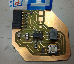
- Add a button and LED (with current-limiting resistor)
- Check the design rules, and make it
Redraw the board
First we reviewed some electronics rules with our instructor Federico Vanzati and this helpful page.
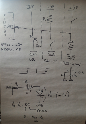
I'm not an expert about eletronics, so I found a little bit difficult to understand everything, but I learned behavior mode of a simple LED and a button.
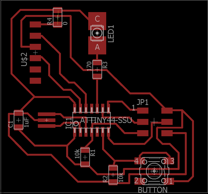
I will use these few rules to calculate value resistor near the LED, so it doesn't break: I will search datasheet of my white LED (I found here)...now I know my resistor value has to be 170 Ohm!
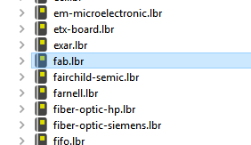
Second step was to open Eagle and to load fab library: in order to have right components, I downloaded the fab.lbr file,I found libraries folder in Eagle, and I made a simple copy and paste; then I went in Eagle's Control Panel, and inside "Libraries" I found my fab.lbr
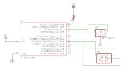
I started a new schematic: adding components is very simply, you have to go in components list, find the right component seeing "echo hello-world" page, and finally click on "Add".
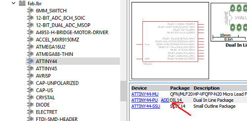
I started with Attiny44 at center, then I watched component datasheets (often with Google search) and finally I connected them each other with a simple drawn line. Be as "clear" as possible when you position the components, it will be useful to simplifly the construction of the board.
I often used copy/paste for similar components (like resistors), but remember to change the value if you need different working.
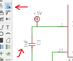
For example, here I set capacitor value in 1 uF.
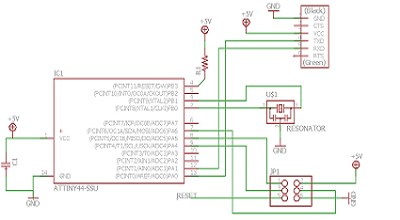
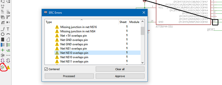
At the end of schematic design, you have to launch ERC command that check your scheme and point out your errors: in my case, it found many errors of overlap between connections and pins; I had to fix them to continue, until there were 0 errors.
Now I have my schematic file and I can switch to the board. Eagle automatically puts all the components on the left out of working area.
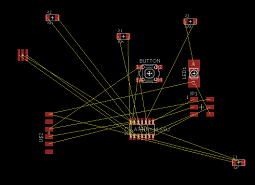
I started to move some of them thinking final appearence, but I realized that this approach would complicate the routing. Logical connections with yellow lines are not user friendly.
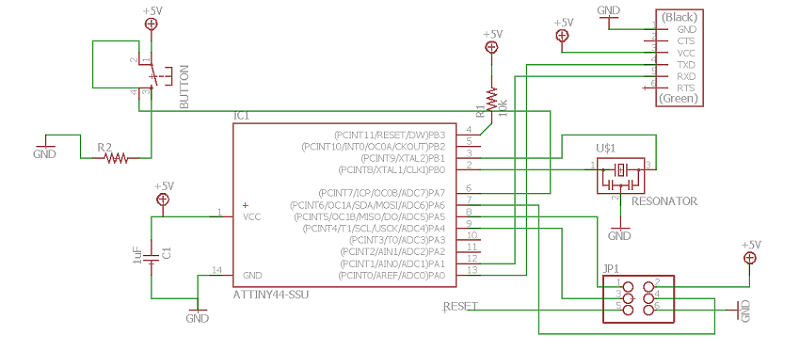
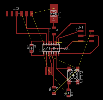
With the help of my classmate Gianfranco Caputo (thanks!!) I switched to schematic, I checked connections between microcontroller and components, and I positioned components near the right microcontroller pin: for example, capacitor is better on the left of microcontroller so it will be near pin 1 and 14 to which must be connected.
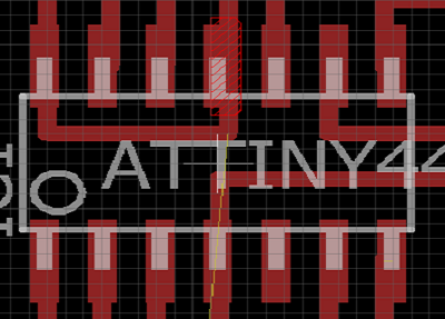
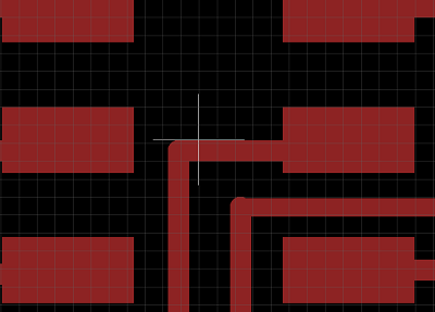
I spent most of the weekend to move components, to change routes, to close and restart the board, but at the end I always needed two bridges with resitors (value 0) to connect ground and supply..2 bridges are too many! I looked at 2015 students archive and EUREKA! I have to draw two routes under the microcontroller (instead of one), and one route where I thought there was no space.
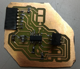
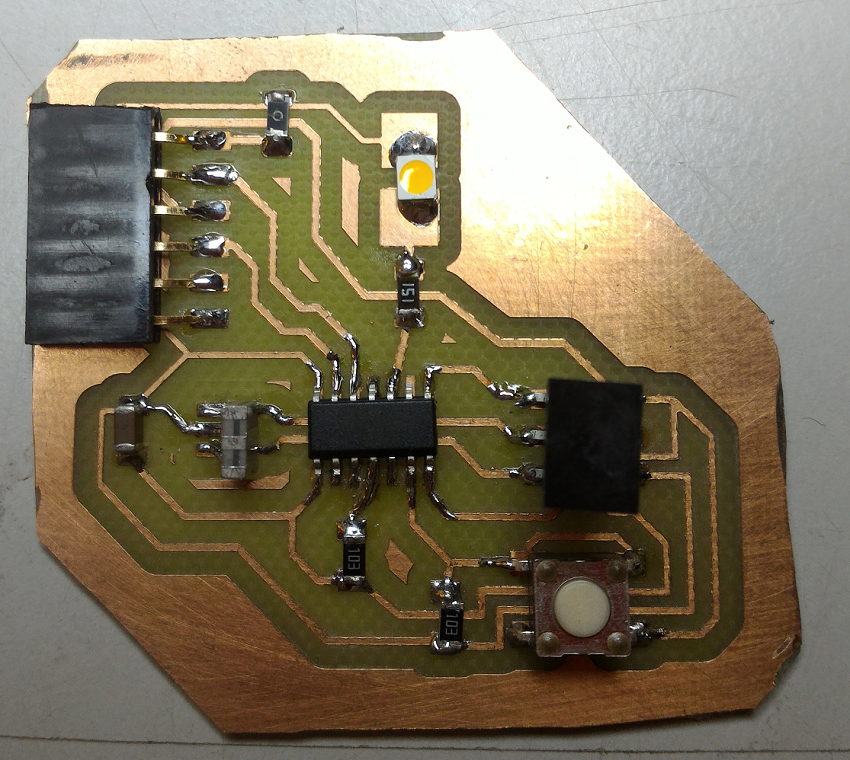
After many many changes and aesthetic improvements finally I have my board with led and button (here brd file).
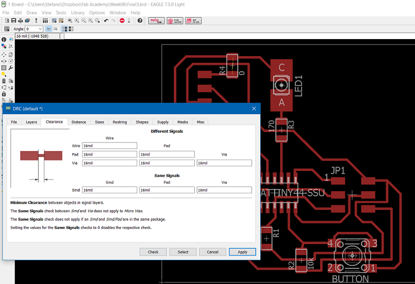
The last important step was the DRC command, in particular the tab "Clearance": with it you can check if all components are connected and if everywhere there is enough space between routes and components. I set 16mil to be sure.
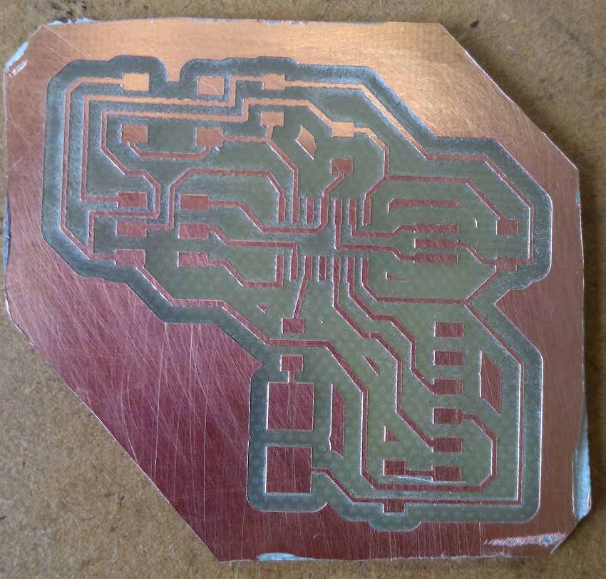
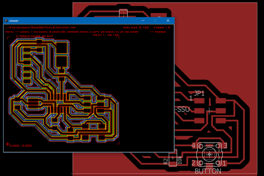
If there are 0 errors and the preview of milling is good, you can launch PcgGcode(a plug-in of Eagle) that generate the .nc file to operate the milling machine (here my file).
Milling and soldering
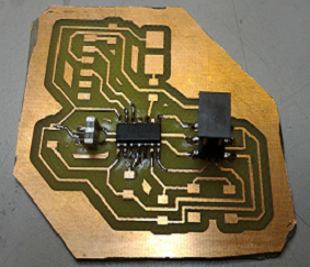
The result is not perfect: the board is too big, and probably in Eagle I used a wrong resonator, because my real resonator is bigger than the schematic one.
I solved the problem by soldering resonator in "vertical" way.