Week 13
Output Devices.
ASSIGNMENT:
1.) Add an output device to a microcontroller board you've designed and program it to do something.
ASSIGNMENT:
1.) Add an output device to a microcontroller board you've designed and program it to do something.
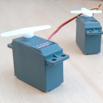
This week we had the task of experimenting with an electronic output device. In my case, I have experimented with a servo because possibly use a pair for my final project. Basically this week I experimented with the servos to understand how they work.
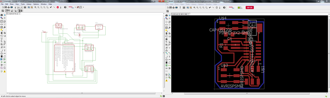
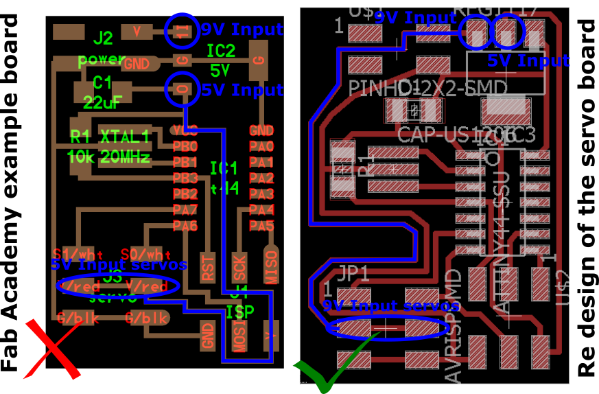
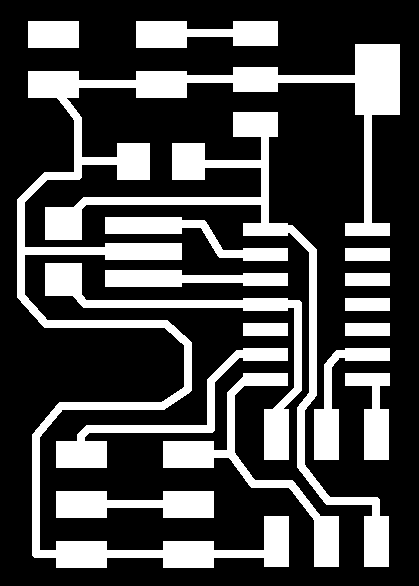
I used Eagle to design my board, based on the example of the Fab Academy schedule "Hello.servo.44".
Design the board was practically simple, but just as I had problems with my design because I was using some erroneous components and some wires were mistakenly connected.
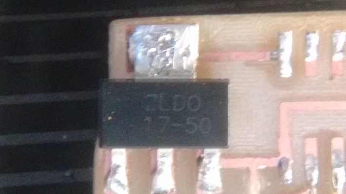
- The voltage converter which used was different from what appeared on the schedule board.
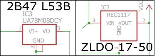
In the Fab Lab TECSUP, we only had available the voltage converter ZLDO 17-50, and in the example of the schedule indicated the 2B47 L53B converter.
The difference between the two are as follows:
In the 2B47 L53B Converter have PIN 1 (Vinput), PIN 2 (GND), PIN 3 (Voutput), and in the 17-50 ZLDO Converter have PIN 1 (GND), PIN 2 (Voutput) PIN 3 (Vinput). It is important to be careful with the wire connections to the pins.
- Power to the servos was 5 V, the servos run to 9 V and for this reason my board caused short circuit.
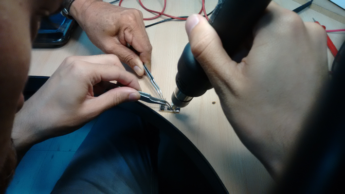
When I could fix the errors found on my board, I could mechanize and finally solder the components.
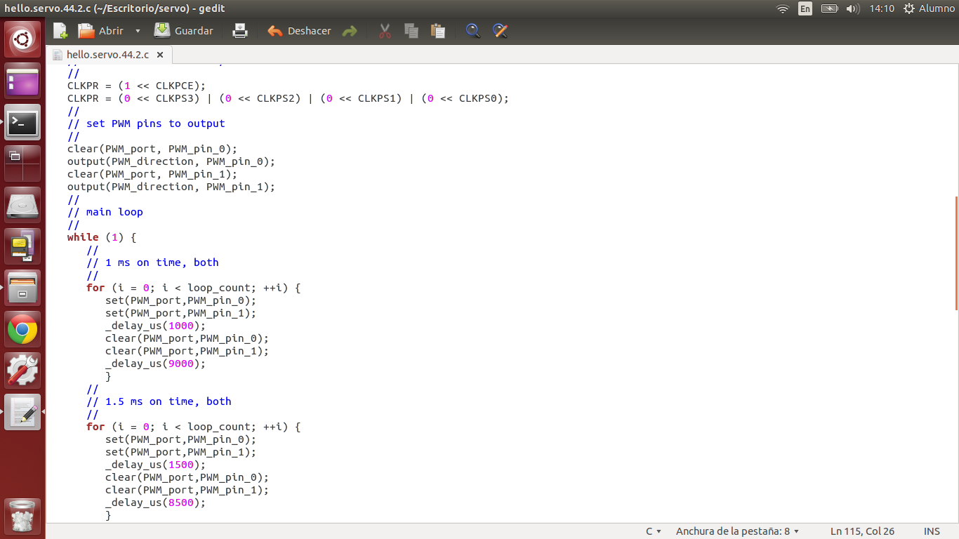
To program the board, I downloaded the "C (hardware PWM)", "C (two-channel, software PWM)" and their respective "makefiles" files , with the help of this software could program the machining of the mold.
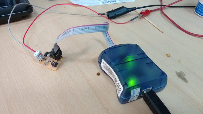
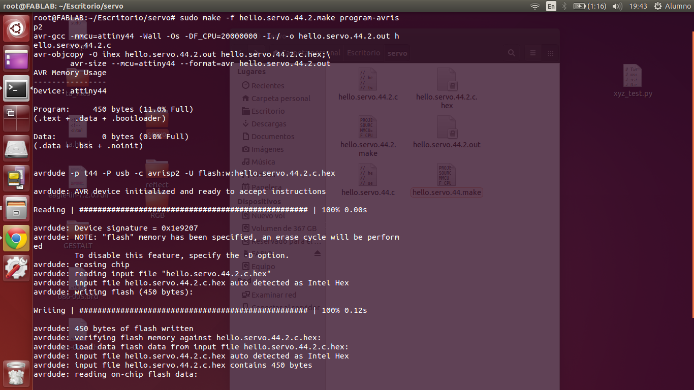
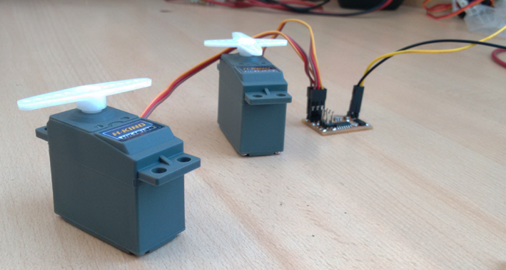
I plugged my board to the atAvrisp2 programmer and feed 9V power supply, using Ubuntu proceeded to program the microcontroller with the previously downloaded files.
After the programming of the board, I connected the servos and did a test to see how they worked.
Later, I started to play a bit with the file "C (two-channel, software PWM)" by modifying some values within the code, thus could modify the movements of the servos.
With the help of an oscilloscope, I check the operation of the circuit. The above equipment allows me to graphically observe the servo signals sent from the microcontroller.
Eagle file: Servo2.brd
Eagle file: Servo2.sch
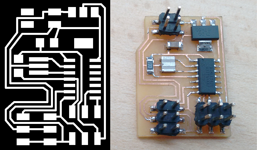
Circuit PNG: traces_servo2.png
Circuit Cut Out PNG: cutout_servo.png
You can download more files here from DROPBOX.
- The servos work correctly.
- I can experiment with a possible devices for my final project.
- I had problems with voltage converter.
- Connect a Ultrasonic Sensor with a servo.
I'm currently taking this course in FAB LAB TECSUP, in Lima-Perú, through CIDI FADA UNA with the support of CONACYT and PARQUE TECNOLOGICO ITAIPU FOUNDATION


©DESIGNED AND BUILD BY FABIO IBARRA - FAB ACADEMY 2016
EMAIL: fabioibarrab@gmail.com