Design and build a wired &/or wireless network connecting at least two processors
I used App inventor 2 to make Android smartphone application for networking and communications this week. The main function is that connects satshakit with bluetooth to sent the Moisture Sensor's data to the phone interface. The Moisture Sensor is making by myself. That is one of the project's function. The most important function is controlling the Moisture content in this cropping system. Useing MCU to record numerical from monitor and transports to the mobile terminal. To prevent watering too much or not and it can't get the truthful parameter, I use that to make easy way to understand real parameter. Although Homemade sensor i can't get precision data, still can analyze tendency to know the moisture content. 本周networking and communications 我使用App inventor 2做了Android smartphone application,主要功能為使用藍芽通訊協定連接satshakit,將自製的水分感應器所取得的數值,傳回手機介面上顯示。其為期末專案中一項功能,種植系統中最為重要的功能即為水分的控制,由MCU讀取測器數值,並由通訊將資料擲到手機端做顯示輸出。方便人們了解種植系統中實際的讀取數值,而不是瞎猜植物的生長參數,胡亂的澆灌過多水分或過長時間不澆水而太乾涸。雖然自製感測器離真實數值有段距離,但依舊可由資訊收集、分析趨勢來判斷水量多寡,尚具實用性。
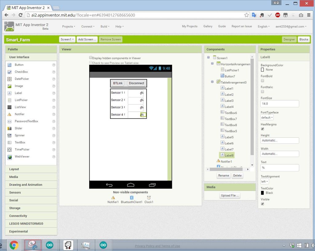
As described in Week10, App inventor 2 as first in " Designer "Design user interface. The same has Bluetooth connect / disconnect button, the second region after receiving value as compared with the display text field contains Label, TextBox functional device, and another warning message Notifier element, BluetoothClient communication, Clock timer function components. and use the property (properties) field to adjust the layout of the above elements, text size, background color, alignment and other display interface, can be arbitrarily set until satisfactory UI appears. 如同Week10中所述,App inventor 2一樣先在""Designer"設計使用者介面。此次相同的有藍芽連接/斷開的按鈕,第二區則為收到數值後做為顯示的各項文字欄。包含Label, TextBox功能元件,另外有Notifier訊息警示元件、BluetoothClient通訊功能、Clock計時器功能元件。並使用屬性(Properties)欄位調整上述元件的布局、文字大小、背景顏色、對齊等顯示介面,可任意設定直到滿意的UI出現。
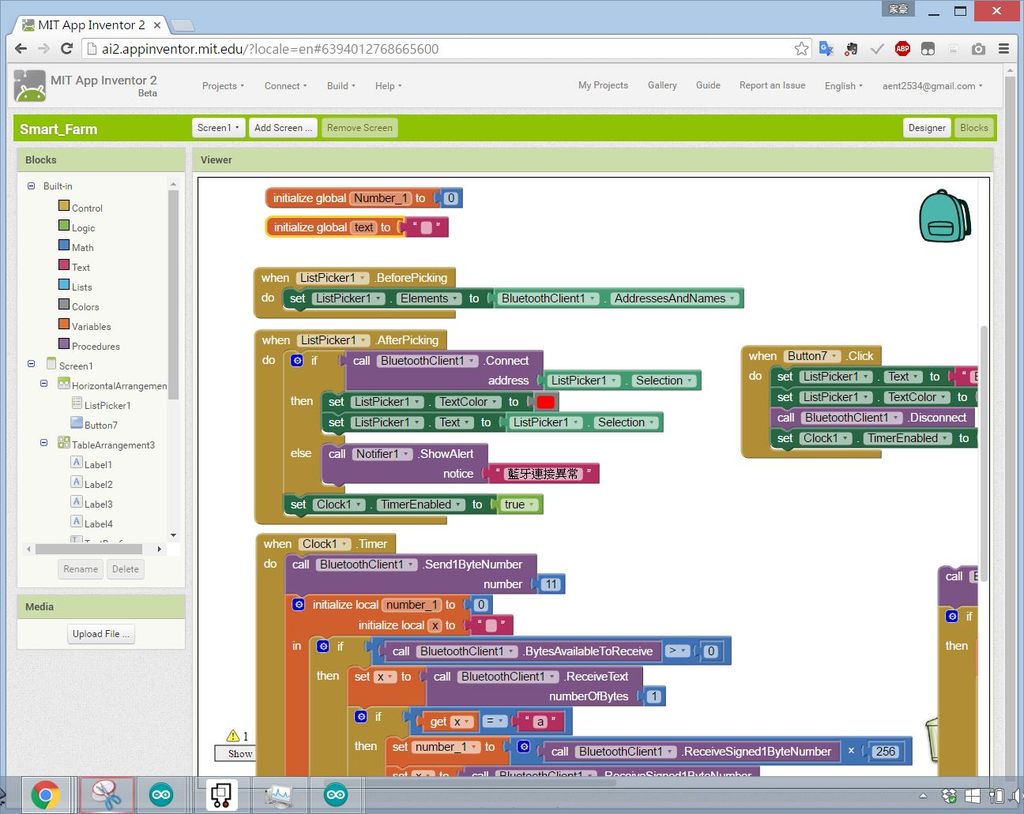
After completion of the design interface, click the "Blocks" to switch to the program edit page. In various pieces of the puzzle to complete the picture on the left programmable logic editor. 完成介面設計後,點選"Blocks"切換到程式編輯頁面。以畫面左側各種拼圖塊完成程式邏輯編輯。
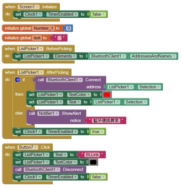
The first part is a screen initialization, variable declarations, and Bluetooth connection / disconnection functions. By using a timer (clock) function takes a value when initializing have to stop, timed to be completed before opening the connection. At the same time before the Bluetooth connection, Bluetooth phone connected devices to obtain the name and address. After clicking the connection to determine whether the normal connection, the device name and address of the text will appear when wired correctly, if you can not connect prompt abnormal. When the button was clicked 7, para open communication, reply to the menu text and color, and the timer was stopped, to avoid receiving / sending data. 第一部分是畫面初始化工作、變數宣告以及藍芽連線/斷線功能。因使用計時器(clock)功能取數值,當初始化時得先停下,待完成連線才開啟計時。同時在藍芽連線前,取得手機中藍芽連線裝置名稱及地址。點選連線後判斷是否正常連線,正確連線時文字會出現裝置名稱及地址,若無法連線則提示異常。當按鈕7被點選時,段開通訊,回複選單文字與顏色,同時得停下計時器,避免在收/送資料。
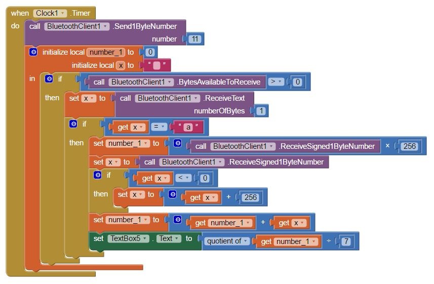
The second part is the main program, and when the timer starts to trigger per second (adjustable), to send "11" to the remote device, be ready to receive signals. And set the variable region, following a remote unit to send back signals. When Bluetooth signal is received, the first to open the first judgment of thing is not received word 'a', if properly receive other down in value, and then restore the original value calculated. This function is required because the original sensor signals received digital range of 0 to 1023 values, but the value Bluetooth communications transmitted to 1byte, transmit digital range of 0 to 255, so that the distal end of the device will do 0 to 1023 dismantling, the value is divided by 256, and the resulting quotient and remainder, these two values are greater than 0 and within 1byte, can be passed directly. Transmitted first quotient, multiplied directly after receiving the 256 plus the remainder to restore value. To note here is that when the bits transmitted in binary notation, represents a value of -128 to 127. The remainder may be up to 255, more than 127 are sent by a negative value, so when the received number is less than 0 when coupled with the reduction of 256. The quotient is not required because the quotient of the maximum value of 1023/256 = 3.996, not greater than 127, it will not transfer negative. Finally, the reduction of the value divided by 7 and then displayed on the text field. 第二部分為主要程式,當計時器啟動並以每秒觸發一次(可調整),先發送"11"到遠端裝置,進行接收訊號準備。並設定區域變數,承接遠端裝置送過來的訊號。當藍芽接收到訊號時,開啟先判斷第一位接收到的事不是文字'a',若正確在往下接收其他數值,然後計算還原原始數值。需要此功能是因為原始感測器訊號接收到的數字範圍為0~1023的數值,但藍芽通訊傳送的數值為1byte,傳送數字範圍為0~255,所以在遠端裝置將0~1023做拆解,將數值除以256,將得到商及餘數,此兩數值皆大於0且在1byte內,可直接傳遞。先傳送商數,接收到後直接乘以256再加上餘數即可還原數值。此處要注意到的是位元在傳送時以二進位法表示,所代表數值為-128~127,因餘數可能達255,大於127時送過來的數值為負數,因此當收到數字小於0時加上256還原之。而商數不需要的原因是商數最大數值為1023/256=3.996,不會大於127,所以不會傳送負數。最後將還原的數值除以7再顯示於文字欄上。
Postscript: subsequent discovery of the global variable does not need to initialize the set, because the timing loop in the variable region and do undertake converted into text display after no storage needs. 後記:後續發現初始化所設定之全域變數並不需要,因計時循環中的區域變數做承接與轉換成文字顯示後即沒有儲存的需求。
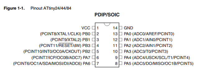
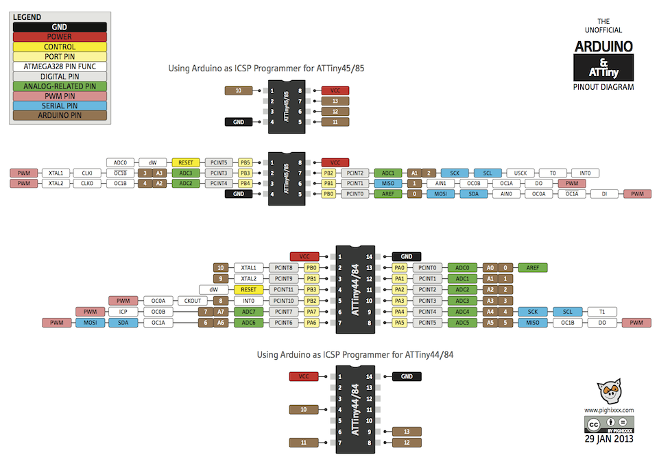
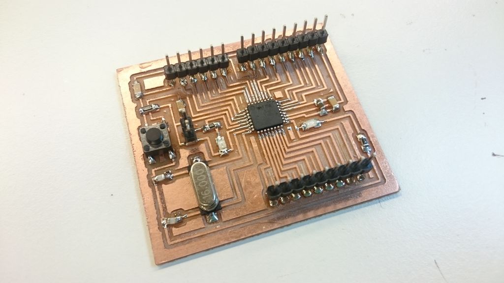
At first I used the remote unit microcontroller Attiny 44, having a 4K memory and internal 8MHz oscillator, surrounding a small project is not high demand can reduce a lot of passive components, feet and cost less to increase the chances of success, refer to the figure up to 11 groups I / O, analog read up to eight groups, containing two PWM outputs. Pin9 & Pin10 can be connected to an external oscillator, using higher when more accurate clock. 遠端裝置起初我使用微控制器Attiny 44,其具有4K記憶體及內部8MHz震盪器,小型專案周邊需求不高可以縮減許多被動元件,腳少成本及增加成功機會,參考下圖多達11組I/O,類比讀取達8組,含有2個PWM輸出。Pin9&Pin10可接上外部震盪器,使用更高更準確時脈。
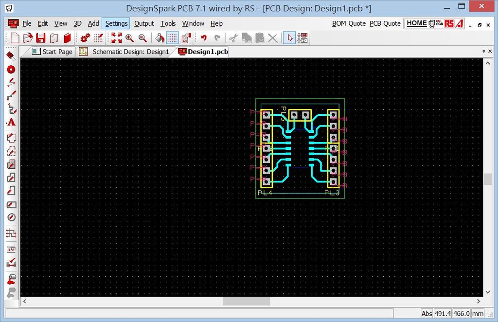
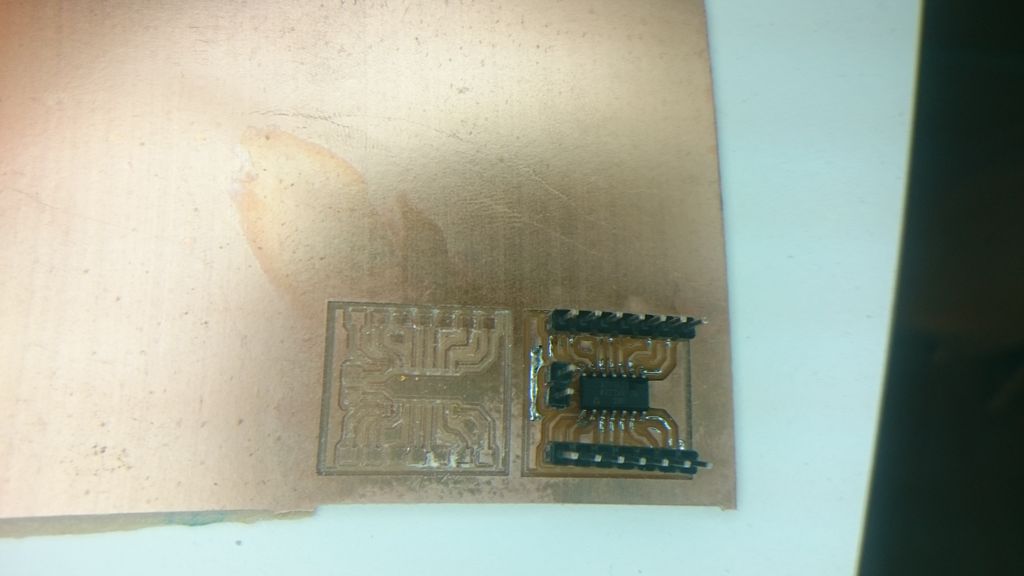
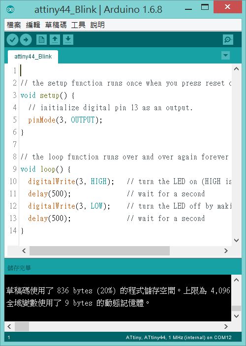
In Design Spark PCB designed to draw out the circuit is very simple and will Attiny 44-pin pin has been drawn, and a group of more than Vcc / Gnd. Arduino IDE has been successfully rewritten Blink LED is lit, but the internal 1MHz oscillator I chose to compile upload time if the election is 8MHz, LED lights on and off time program is different from the 0.5s, actually about 4s, presumably internal shock It does not work at this time under the pulse. 以Design Spark PCB繪製所設計出的電路十分簡易,將Attiny 44接腳已排針引出,並多了一組Vcc/Gnd。已Arduino IDE改寫Blink點亮LED成功,但內部震盪器我選擇1MHz進行編譯上傳,若是選則8MHz時,LED亮與滅時間不同於程式上所述0.5s,實際大約是4s,推測是內部震盪器無法在此時脈下工作。
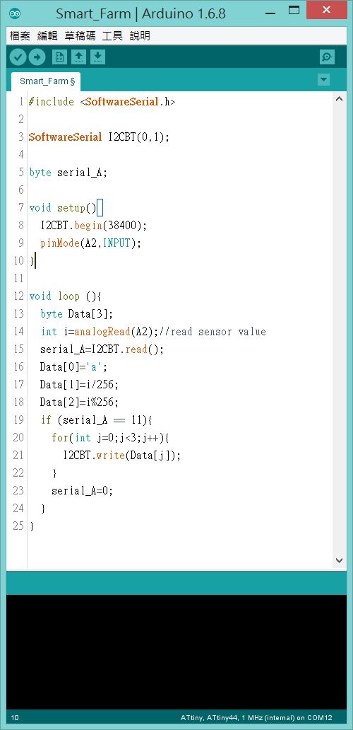
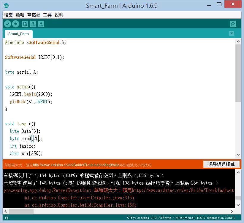
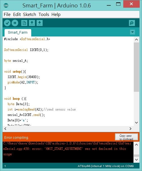
After start editing MCU program. Importing the first paragraph of Bluetooth communication library; "SoftwareSerial.h" and set the communication pin. In the second stage set of variables, Bluetooth communication baud rate (refer Week10), set the read humidity pin. The third is the continuous loop of the main program, set the local variable i read analog value. And received a check for Bluetooth received "11." Data storage array, respectively: the text 'a', i quotient, i remainder, as described in the preceding paragraph, the value i is 0 to 1023, so in addition to the 256 for dismantling. If you received '11', the continuous transmission Data array data. After serial_A back to 0, wait for the next reception. 之後開始編輯MCU程式。第一段匯入藍芽通訊library;"SoftwareSerial.h"並設定通訊腳位。第二段設定變數以、藍芽通訊鮑率(參考Week10)、設定讀取濕度腳位。第三為不斷loop的主程式,設定區域變數i讀取類比數值。並檢查有無收過藍芽收到"11"。Data陣列則分別儲存:文字'a',i的商數,i的餘數,如前一段所述,i的數值為0~1023,所以以256除之作拆解。若有收到'11',則連續發送Data陣列中資料。結束後serial_A回到0,等到下一次接收。
The draft code was found too, can successfully compiles but does not upload. Beyond Attiny44 can store space. 發現草稿碼太大,可以順利編譯但無法上傳。超出Attiny44能儲存的空間。
Note: Follow-up examination was found to be more than a declaration of a lot of unnecessary parameters and code rewrite to simplify the subsequent program to less than 4K byte. Note:後續檢查才發現是多宣告了很多不必要的參數及程式碼,後續改寫簡化程式即可小於4K byte。
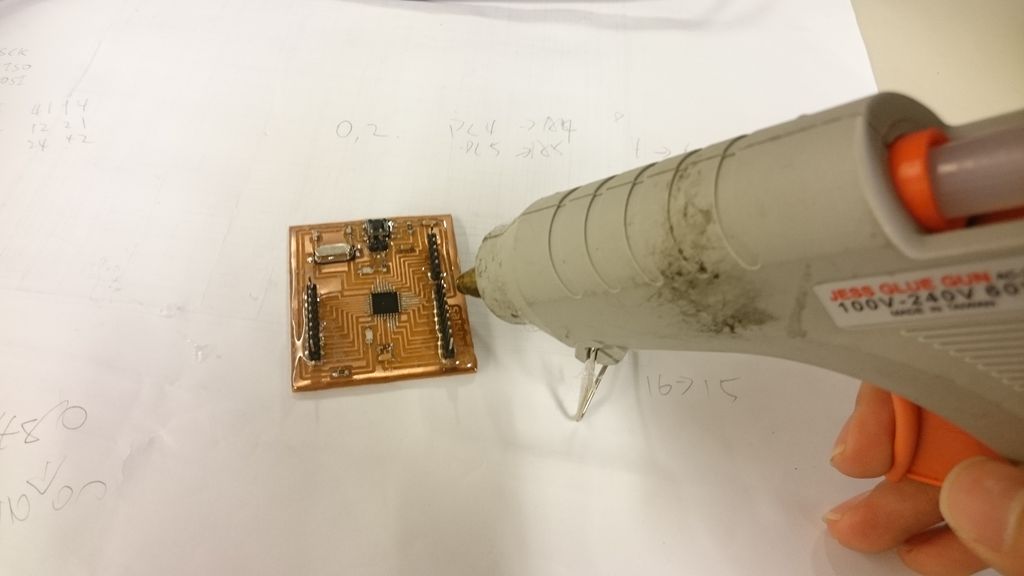
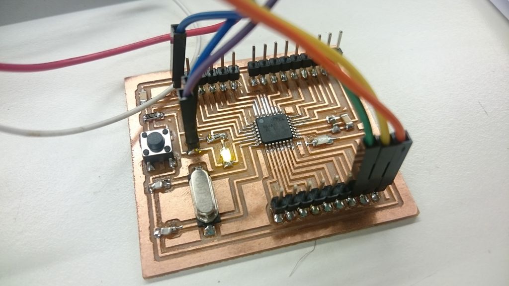
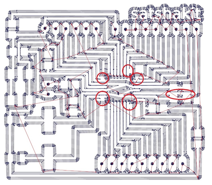
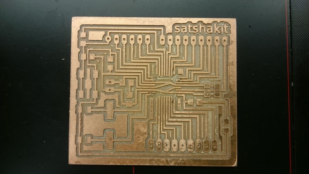
Because the draft code is too big, so instead satshakit, which has a 32K internal capacity can be used, I / O numbers are more (digital read fewer pins, PWM and analog output pin becomes large). Reference Github, engraving machine with SRM-20 processing and electronic components welded to Arduino IDE example Blink file test whether the normal burning, lit the first 13 pin LED, flash time is correct. When the confirmation is no problem to Make friends "hot melt glue" gun painted surface, the protection circuit board is not easy to break, but also solve the problem FP1 foil can easily be peeled off. After painted hot air gun hot melt glue gun can be used to blow the surface smooth. 因草稿碼太大,所以改用satshakit,其內部具有32K容量可使用,I/O數目也更多(數位讀取腳位變少,PWM及類比腳位輸出變多)。參考Github,以雕刻機SRM-20加工及焊接上電子元件,以Arduino IDE範例檔案Blink測試是否能正常燒錄、點亮第13隻腳位LED、閃爍時間是否正確。確認都沒有問題時,以Make的好朋友"熱熔膠"槍將表面塗滿,保護電路板不易斷路,也可解決FP1銅箔容易被剝落問題。塗滿後可用熱風槍將熱熔膠槍表面吹平整。
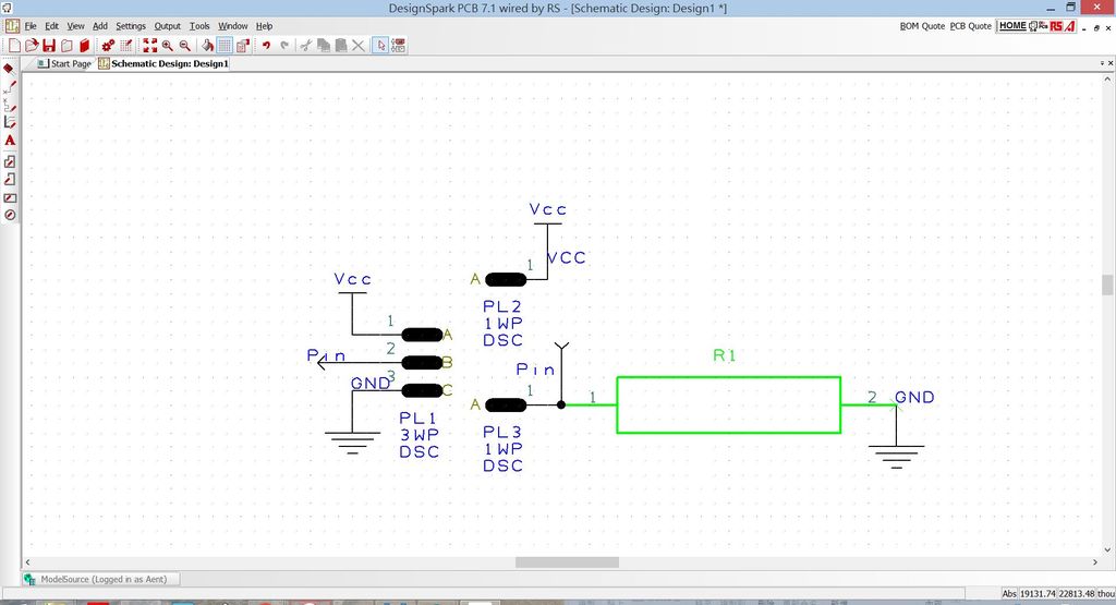
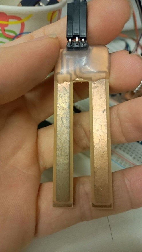
As in the first week 11, the measurement of moisture values I also use the fixed assignment voltage (Voltage divider rule) principle, the use of water-weak electrical properties (soil with more ions, better conductivity), the amount of water is converted into Z1 V_out value, and then by the MCU to read and record 如同第week 11,量測水分數值我也使用電壓分配定則(Voltage divider rule)原理,利用水可微弱導電特性(土中帶有更多離子,導電性更佳),水的多寡轉換成Z1的V_out的數值,再由MCU讀取與紀錄
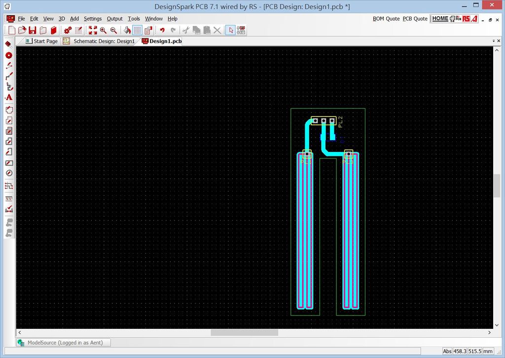
Use Designspark PCB circuit schematic drawing. 使用Design Spark PCB繪製電路原理圖。
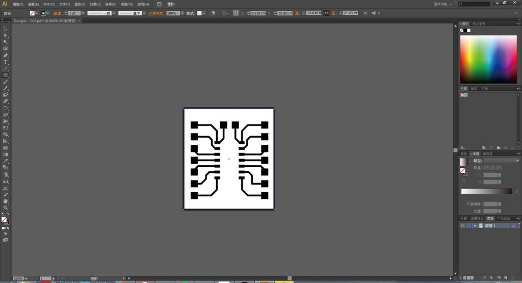
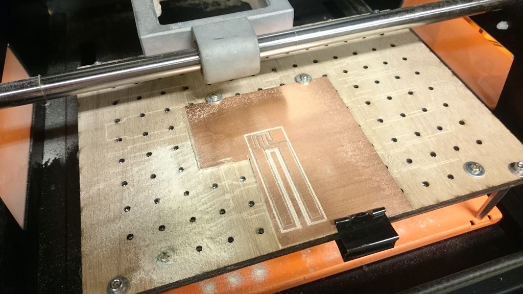
Schematic convert PCB Layout. SHOP copper electrode portion is used to draw lines or coarser desired range. And convert the drawing to Roland engraving machine code. (This process and method can refer to my week 6 step) 將原理圖轉換成PCB Layout。電極部分則使用鋪銅或是較粗的線路畫出所需範圍。並轉換圖檔至Roland雕刻機code。(此段過程與方法可參照Week6步驟)
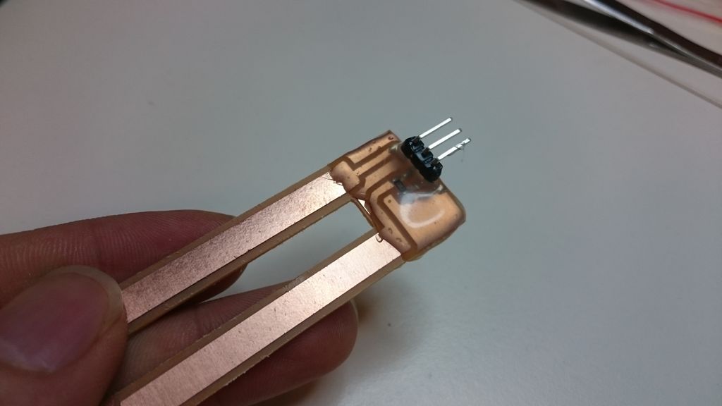
Use SRM-20 sub-engraving published and welded pin and a resistor, the upper half of pin positions are also coated with hot melt adhesive glue gun to avoid short circuit protection board. 使用SRM-20雕刻出版子,並焊上排針與電阻,上半部排針位置也以熱熔膠槍塗上熱熔膠避免短路也保護板子。
Hear is Sketch.
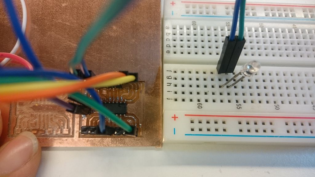
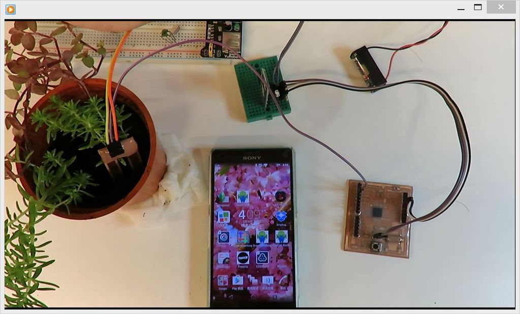
After burning program, the sensors, the control panel, Bluetooth module to connect. Connect the power to test operation.Actual results as shown in the video. 燒錄程式後,將感應器、控制板、藍芽模組進行連接。接上電源進行測試運作。實際結果如影片所示。
Troubleshooting:
Setting Arduino IDE when it has compiled attiny series IC functions, some compilers may not be applicable to compile internal oscillator. For example: Cipian download version of the IDE or arduino-tiny-0150-0020.zip, decompressed data into the arduino will install the appropriate folder under as: C: \ Program Files (x86) \ Arduino \ hardware \ arduino. This IDE are two ways of selecting the internal oscillator at compile time appears Error, the subsequent switch to other Library to solve. 設定Arduino IDE使其具有編譯attiny系列IC功能時,部分編譯器可能無法適用內部震盪器進行編譯。例如:此篇下載的IDE版本或以arduino-tiny-0150-0020.zip,解壓縮後將資料放到arduino安裝相應的資料夾下,如:C:\Program Files (x86)\Arduino\hardware\arduino。此兩種方式之IDE在編譯時選擇內部震盪器會出現Error,後續改用其他Library才解決。
Attiny44 insufficient memory space to use Bluetooth draft code, thus changing the selection of the IC satshakit ATmega328p. Attiny44內存空間不足以使用藍芽草稿碼,因此改選用ATmega328p的IC的satshakit。
Because I use the chisel is 0.4mm, after some fab modules operation pin will not be carved out, carving manually after the short-circuited portion were ground. 因為我使用雕刻刀俓為0.4mm,fabmodules運算後有部分接腳不會雕刻出,雕刻後需手動將短路部分磨除。
When using copper as an electrode, it was found positive oxidation serious. After the study found that the surface of commercially available kits tin shop, subsequent use may be on more than one ˙ tin solder, to extend the use of time. 使用銅箔作為電極時,發現正極氧化嚴重。研究後發現市售套件表面有鋪錫,後續使用可能多焊上一層˙錫,延長使用時間。
The Fab Academy is a Digital Fabrication Program directed by Neil Gershenfeld of MIT's Center For Bits and Atoms and based on MIT's rapid prototyping course, MAS 863: How to Make (Almost) Anything. The Fab Academy began as an outreach project from the CBA, and has since spread to Fab Labsaround the world. The program provides advanced digital fabrication instruction for students through an unique, hands-on curriculum and access to technological tools and resources.
Fab Lab Tainan was founded at Dec. 2013 at Tainan, Taiwan. It is the first Fab Lab at Southern Taiwan. Supported by Tainan City Government, this Lab hope could open for local citizen. The background photo of web page is the roundabout in front of Tainan train station.
I'm Jia-Hao Chang from Fablab Tainan.I'm senior staff of Association of Digital Culture, Taiwan (ADCT).In this years, I have participated the project of digital curriculum.My career is to empower people employing digital manufacturing technology or tools toimprove their problem.