The Build Process
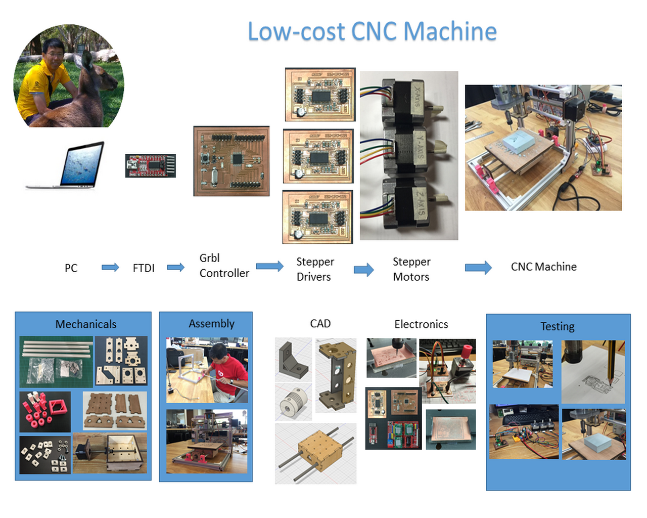
Click on the link to view my presentation slide, which gives an overview of the different components of my low cost CNC machine and how they are linked.
Mechanical Design
After much deliberation, I decided to build the frame of my CNC router out of aluminum profile, rather than wood. I chose aluminum rather than wood for the structure because it is stronger, more rigid and quality is more easily controlled, compared to getting wood in Singapore. The plywood that we get here are mostly of lower grade and meant more for external hoardings at construction sites, rather than project use.
Another major decision that I made was to design a movable platform CNC router, rather than a gantry design. Since I wanted my build to be low-cost and portable, it seemed more appropriate as a first design. My gantry system will have to wait for another build.
The Frame
The dimensions of my frame were largely determined by the length of the threaded rods from the stepper motors that I was using. These motors are spare motors that we ordered as part of the MTM group project. They come with integrated 300mm threaded rods, so my x- and y-axis dimensions are limited to that sizse. I also opted to use 20x20mm aluminum profiles, which meant that the lengths of aluminum profiles needed were 290mm and 250mm.
Misumi is a major supplier of mechanical parts in Singapore and I modeled my Al profile based on the dimensions of the 20x20 Al extrusions from the Misumi catalog. For the 90 degree angle brackets, I also modeled these after parts that I found in the same catalog. I purhased the aluminum profiles, M4 bolts and insertion-nuts for use in the assembly process.
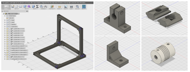
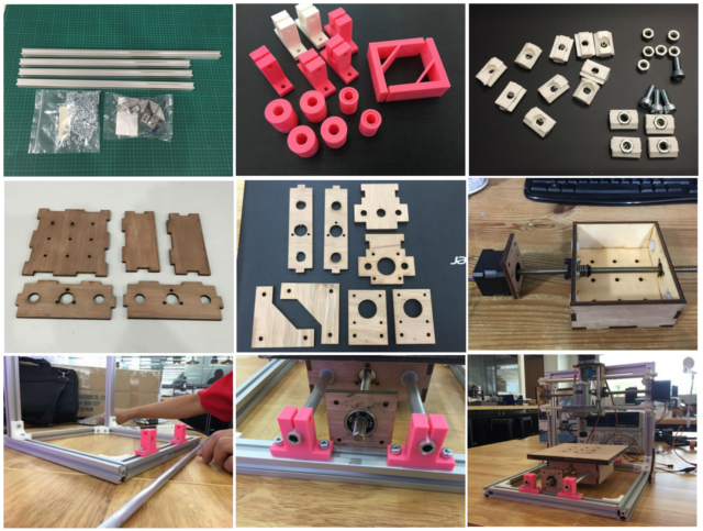
Neil wanted us to make as many parts as possible, rather than buy off the shelf components, so I modeled and 3D printed the 90 degree angle brackets, insertion-nuts, linear-rail shaft supports, linear bushings and 5-to-8mm flexible couplers. In the end, I opted to use the nylon bushings that came with the stepper motor kit, rather than my 3D printed version.
The CAD models for the frame structure and some of the 3D printed mechanical parts are shown in the pictures below.
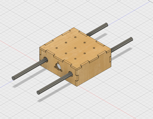
Y-Axis Assembly
For my y-axis design, I made a basic box-frame to hold the anti-backlash nut of the threaded rod and the nylon bushings for the linear support rails. I decided to keep the size of the box to 120mm and add another layer for the router bed, as this would give me more options on the final size of my work area.
The linear shafts are supported by 3D printed shaft support pieces modeled after parts from the Misumi catalog. The vertical height of the hole for the shaft support is 20mm and I designed the mounting brackets for the stepper motors to match that height. Likewise for the bearing support at the other end of the threaded rod. For the bearing support for the free end of the threaded rod, I used standard 608zz bearnings, which I "borrowed" from an old pair of inline skates that I had. If you look closely at the 608 bearings, you can see that the face plate on one side has been removed. I removed them for my inline skates, as it made oiling and cleaning the bearings much easier :)
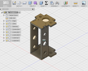
X and Z-Axis Assembly
The X and Z-axis assembly are integrated as a unit. I designed this structure to be small, yet large enough to hold a reasonable size spindle motor or dremel tool. The x-axis structure holds the anti-backlash nut for the x-axis thread rod and the nylon bushings for the linear shaft. The structure was modeled in Fusion 360 and exported as dxf, then laser cut on 5mm plywood. I opted for 5mm plywood rather than 12mm, as this machine is essentailly a first prototype and I wanted to test if this was strong and rigid enough to support the spindle motor.
The cad model used a parametric design, with thickness of material set to 5mm. I did not adjust for the laser kerf (0.1mm), as I intended from the start to reinforce the joints by using a new staple gun that I bought to shoot a nail through the joints to reinforce them. Press-fit is great, but I do not have confidence that it is sufficient to hold the entire assembly together when the machine is in operation.
Motor mount plate and linear rail shaft support design is similar to that for the y-axis assembly. The pictures below show the final assembled x and z-axis mount.
I originally intended to use a pair of linear bearing housing to hold the support plate for the z-axis motor mount. However, the parts that I ordered did arrive until the afternoon of our presentation, so I used a HDPE part salvaged from another project as a temporary mount. This resulted in a small misalignment in the mount, which restricted the range of motion of the z-axis, from the designed 60mmto around 40mm.
The x and z-axis assembly was designed with a smaller width, so that my CNC router can have a larger working area. The effective working area for the movable bed is 180 (W) x 170 (D) x 40 (H) mm in the current prototype.
Electronics - Controller Board
I decided from the onset to use open-source software a much as possible, to keep the cost of my machine down. The software had to be user friendly and be compatible with industry standard g-code. The hardware also had to be low-cost and readily available, either fabricated in-house in a fablab or bought off-the-shelf cheaply.
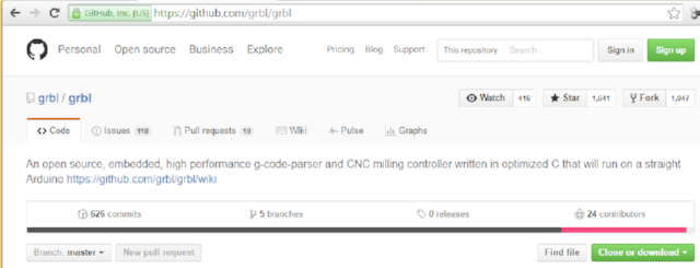
These design decisions led me to explore g-code interpreters running on an arduino-based platform. I decided to use grbl as the control software. Grbl is a popular open-source, embedded, high performance g-code parser and CNC milling controller that runs on the Arduino platform.
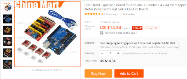
Grbl shields are available that plug directly onto arduino uno boards. These shields support the Polulu A4988 stepper drivers and all parts are readily available at low-cost from many sources and are often used in DIY 3D printer builds. For example, Aliexpress sells a complete kit, including the arduino uno, cnc shield and polulu stepper drivers for USD14.34 inclusive of shipping.
Since I wanted my entire CNC router to be fabbable (i.e. can be made in a fablab, inclusive of the controller and stepper driver boards), I decided to also fabricate my own ATmega382 (arduino compatible) and stepper driver boards.
For the controller board, I decided to try 3 different approaches:
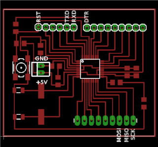
- 1. Satshakit - Daniele Ingrassia developed this board during Fab Academy 2015 and has since come up with a few versions based on his original design.
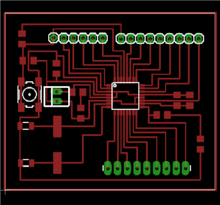
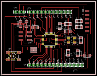
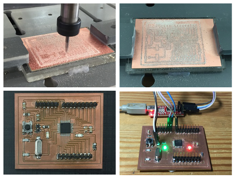
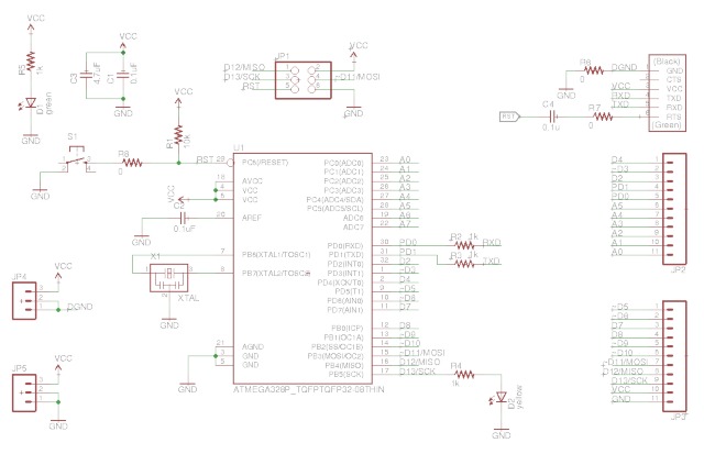
- 2. Fabkit - my on version of an ATmega328-based controller board, with more Vcc and Gnd pins for easy interfacing.
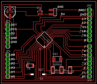
- 3. SPduino - an arduino clone with pinouts that are fully compatible with the arduino uno.
I started with the Satshakit design first. After milling and stuffing the board, the first step is to burn the arduino bootloader into the ATmega328. To do this, I connected my USBasp ISP programmer to the corresponding pins on the Satshakit:
- ISP Pin 1 --> Satshakit MISO
- ISP Pin 2 --> Satshakit VCC
- ISP Pin 3 --> Satshakit SCK
- ISP Pin 4 --> Satshakit MOSI
- ISP Pin 5 --> Satshakit RST
- ISP Pin 6 --> Satshakit GND
Once that was done, the arduino bootloader was programmed onto the fabricated controller board. This is done via the Arduino IDE's Tools > Burn Bootloader option.
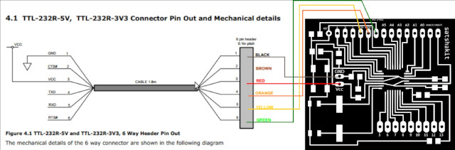
With the arduino bootloader, the microcontroller board can be programmed via the ftdi interface connection. This is done by connecting the VCC, GND, TXD, RXD and DTR pins on the FTDI interface board to the corresponding pins on the controller board. Note that hte TxD and RxD pins have to be swapped, as both the FTDI and control board TxD pins are transmit pins.
Initial testing of the control board was done by loading the Blink example sketch and uploading it to the board. Having successfully done that, it meant that my board was functional.
I think Daniele Ingrassia has done a fantastic job of designing and developing the Satshakit and coming up with so many variations of it. I made the CNC version of the Satshakit for my project when I wanted an ATmega328-based (aka Arduino Uno compatible) controller board. However, in using the Satshakit, I became somewhat frustrated because the entire board had only one Vcc and one Gnd pin each - where the power supply was connected. Programming the board was also somewhat frustrating because unlike the regular Arduino Uno, I had to use jumper wires all over the board, both for ISP programming and especially when I wanted to develop code for the board.
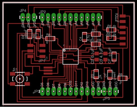
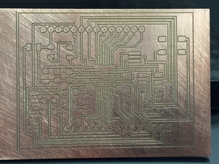
As they say, necessity is the mother of invention - so I decided to complete my own ATmega328 board, something that I started a few months back, but didn't get around to completing, because my need wasn't great enough. I had milled out the board previously, but did not stuff and test it. I have also made some changes to my original board layout, such that the traces are mostly 90 degree and minimising the number of 45 deg traces. I have also replaced the normal PTH round pads with longpads for easier soldering.
I stuffed and burned the Arduino bootloader into my Fabkit controller board, following the same procedure that I adopted for the Satshakit, which I have described above, but via the ISP header instead. I subsequently tested Fabkit programming it using the FTDI USB-TTL adapter and verified that the board worked as designed. I can't wait to test out my board on other projects :)
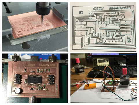
Electronics - A3967 Stepper Driver
One of my early design decisions was to provide users with a choice of between using low-cost commercially purchased stepper drivers or fabricating these in a fablab. For commercially purchased kits, the arduino uno + grbl controller shield and polulu A4988 combination is a very popular choice. The entire package can be bought for less than USD15, inclusive of shipping.
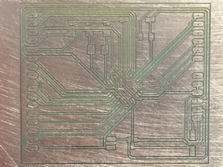
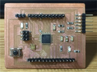
To demonstrate that the stepper drivers can also be fabricated in a fablab, I decided to go with the A3967 stepper controller, used by Ilan Moyer for his Fab-in-a-box project. Ilan has a comprehensive write-up of his project, including eagle files for his stepper driver board at his site.
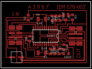
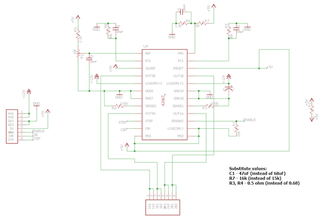
The A3967 stepper driver board made use of some components which are non-standard values in the fablab inventory list. For components which I did not have in our fablab inventory, I made use of the next closest values. We do not have the 0.68 ohm resistors also. To approximate this value, I stacked 2 x 1 ohm smd resistors in parallel and soldered them to the pcb.
Downloads
The cad models and design files can be downloaded using the links below.
- Bracket, linear shaft support, t-slot nut & 5-to-8mm flexible coupler. STL files for 3D printing
- Y-axis assembly. Coreldraw file for laser cutting
- X & Z-axis assembly. Coreldraw file for laser cutting
- Additional frame support. Coreldraw file for laser cutting
- Y-axis base plate & stepper motor support plates. DXF file for laser cutting
- Satshakit_CNC eagle cad files
- Fabkit eagle cad files. Additional Vcc & Gnd pins for interfacing
- SPduino. Arduino shield compatible arduino clone.