Assignment 15: Networking and Communications
I built a radio network using two of my self-made
ATtiny44A-boards: the board for Assignment 6: Electronics Design and
the one for Assignment 13: Output Devices.
Luckily I had added the serial connector for the servo controlling
board, even though it was not needed at that time.
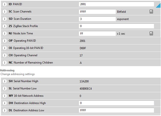
Radio module configuration:
I used three Digi International
XBEE radio modules. One module is configured with the XCTU program
of Digi International as Zigbee Coordinator AT. The PAN ID is
arbitrarily chosen, but is the same for all radio modules. The DL
Destination Address Low is FFFF for broadcasting.
Coordinator:
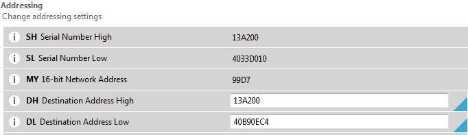
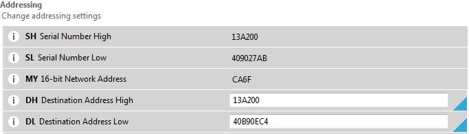
The other two XBEE modules are configured as Zigbee Router AT. The
DH Destination
Address High is the SH Serial Number High of the
Coordinator, and the DL Destination Address Low is the SL
Serial Number Low of the Coordinator. The idea is, that the
Coordinator broadcasts to all Router modules, but the Router
modules send only to the Coordinator.
Node1:
Node2:
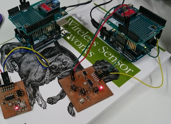
Connections:
The Coordinator is connected to the PC computer using a SparkFun XBee
Explorer USB.
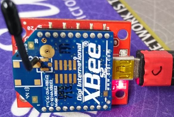
The Routers are connected to an Arduino Wireless Shield connected to
an Arduino Uno board. These are used only as voltage regulators to
power the XBEE modules and the self-made ATtiny44A boards. The
ATtiny board for servos has a 5V regulator and is connected to the
7.5 V Vin of the Arduino, where as the Attiny board without
regulator is connected to 5V of the Arduino. The serial bus pins
from the ATtiny44A boards are connected directly to the Arduino
Wireless Shield pins connected to the XBEE module, as can be seen in
the photograph below. An extra header is used between the Arduino
Uno board and the shield to give access to the serial bus pins.
Application:
The idea of the network is, that the Coordinator transmits the node
number and the corresponding node toggles its LED. After that the
node transmits back its node number and the state of the LED so that
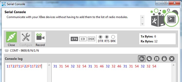
we know it without seeing the LED. Below is an example of the data
traffic. The Serial Console of the XCTU program of Digi
International was used. The blue symbols are transmitted by the
Coordinator, whereas the red symbols are transmitted by the Router
nodes and received by the Coordinator. I tested the range of the
radio link to be at least 20 m, which is about the width of our Fab
Lab.
Software:
The main loop of the Router nodes reads a character from the serial
port, checks if the charater is its node number, toggles the LED if
the node number is correct, reads the state of the LED pin, and
transmits the node number and the state of the LED to serial port.
The code is modified from Neil's
hello.bus.45.c. The main loop is shown below.
#define node_id '2'
...
while (1) {
get_char(&serial_pins,
serial_pin_in, &chr);
if (chr == node_id)
{
// is it
me?
PORTB =
PORTB ^ 0x04;
// toggle
LED
if (PORTB
& 0x04){
// put the
state of the LED in character
ledstate = 'T';
}
else{
ledstate = 'F';
}
put_char(&serial_port, serial_pin_out,
node_id); // send node number
put_char(&serial_port, serial_pin_out,
ledstate); // send LED state
}
}
Files:
Node1
Node2
Home