Assignment 13: Output Devices
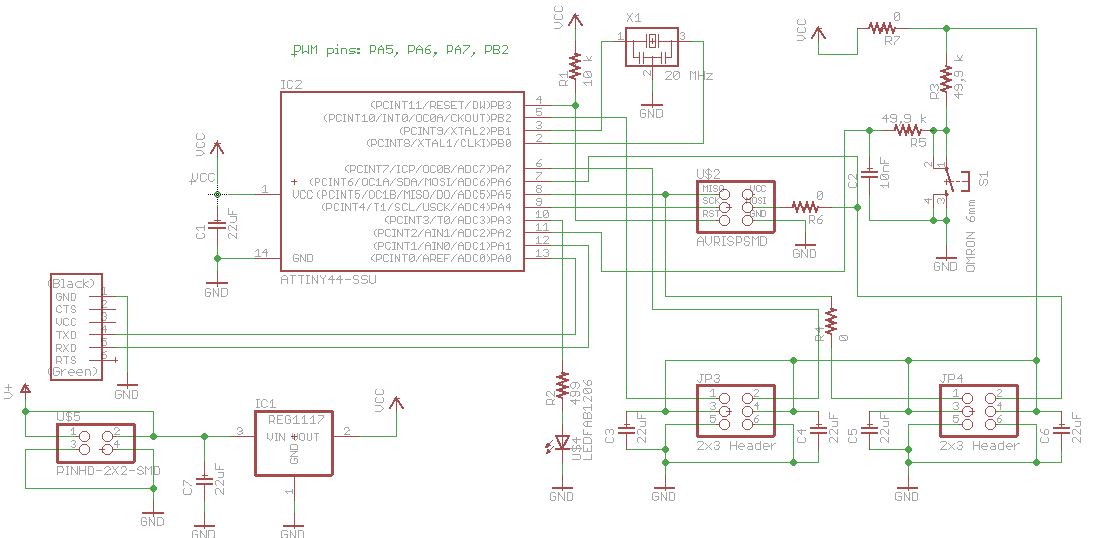
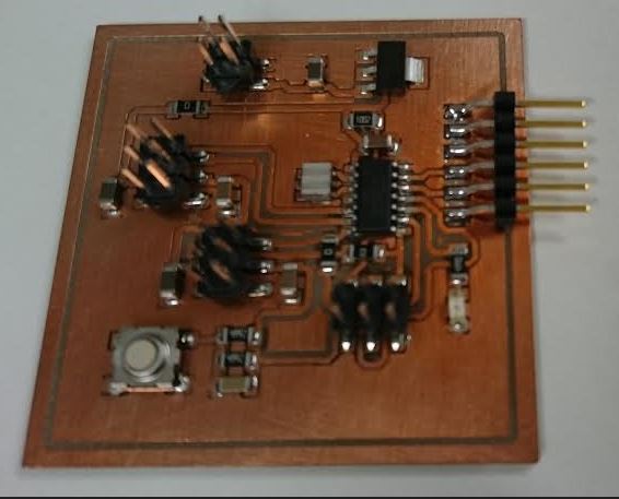
As output devices I use two servos, because this board will be
used also in the final project. I reverse-engineered Neil's servo
board and added two more servo connectors with bypass capacitors,
the FTDI serial cable connector, an LED with current limiting
resistor and a push button with debounce filtering.
After testing my final project I now know, that the bypass
capacitance for the servos is inadequate. The ~100 uF in the
schematic below should actually be something like 3000 uF. Also in
the input of the voltage regulator more capacitance is needed, say
1000 uF. Actually the big capacitance in the of output of the
voltage regulator calls for a protection diode connected from the
output of the regulator (anode of the diode) to the input of the
regulator (cathode of the diode). The idea is, that the big
capacitor is discharged via the diode, not via the regulator. See
e.g. http://www.ti.com/lit/ds/symlink/lm117.pdf.
Programming:
I added
#define F_CPU 20000000UL
in the beginning of the code.
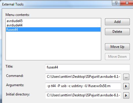
I also added a new external tool configuration to Atmel Studio
to program fuses:
I added direction definition for the LED and push button,
DDRA |= (1 << PA3); //
LED output
DDRA &= ~(1 << PA2); // push button
input
and code to make the LED follow the state of the push button each
time we are in the beginning of the while loop, just to see that
they work:
if (PINA & (1
<< PINA2)){ // with AND-operation check if
bit 2 is set
PORTA
|= (1 << PA3); // with OR-operation set bit
number 3 in PORTB
}
else {
PORTA
&= ~(1 << PA3); // with AND-operation
clear bit number 3 in PORTB
}
Files:
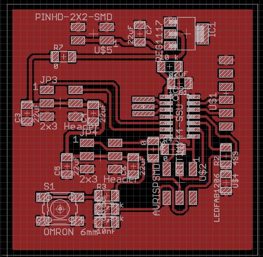
Schema
Layout
Code
Home