In a group, we were to make a machine, including the end effector, build the passive parts and operate it manually. We needed to document the group project and my individual contribution and automate our machine.
My contributions to our group project varied from the initial collaborative brainstorming sessions, to the laser cutting and assembly of the boxes, to the compilation of the documentation of the group project. I was involved in each step of the process as we worked together yet each holding a responsibility for a portion of the project.
We met as a group a week before the Mechanical Design lecture to discuss what exactly we were were going to make as our group project. We drew much inspiration from the Machines That Make . We also looked at many of the previous years designs to draw inspiration. Our debate centered upon one, two or three axis. We wanted to make a wire cutter, lathe or drawing machine. Many ideas were bantered around before we settled upon making a wind chime actuated by the Gestalt machine. This was the brainstorming and I was fully participatory in the process. We even pulled out Lorain County Community College's project from last years Fab Academy to see how they built their machine, which was a zen garden drawn by a metal ball. It was very clever. I noticed that Nadya even mentioned it in her Recitation on Machines That Make.
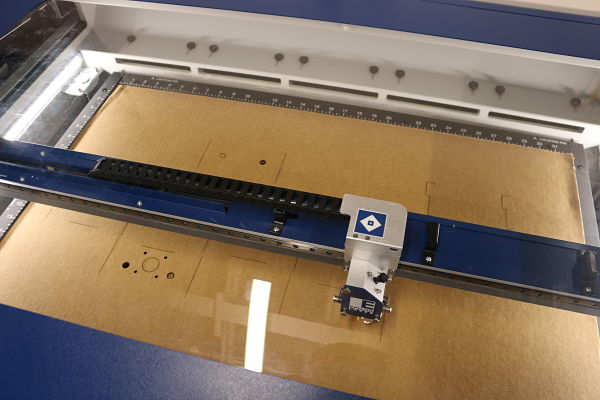
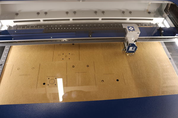
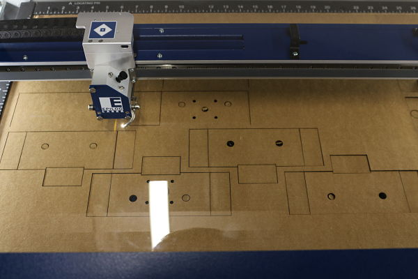
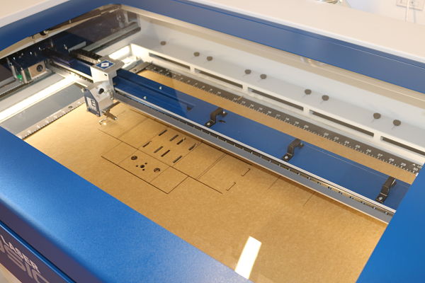
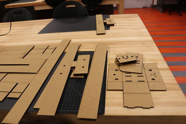
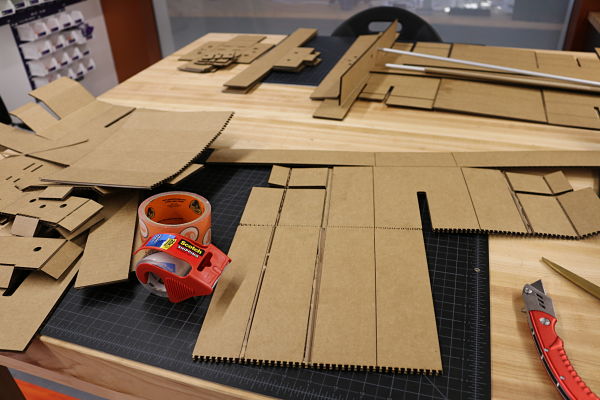
My responsibility was was to cut out the boxes to be used to house the stepper motor and guides. I was not sure how big a laser we needed, so I volunteered to use my new laser which was bigger than what we currently have at the lab. My laser is the Epilog Fusion M2 32 with 50 Watts CO2 laser. I went to the FabAcademy page to download the .dxf file and when I opened it in CorelDraw, I noticed I needed 36" by 24" to cut the original file. I decided to then approach the project by cutting it using the directions for ULINE and the smaller laser. I downloaded the text cutfile and compiled it in CorelDraw to create the .dxf file I needed to cut the box in several layouts to create the box in parts. I used the Color Mapping process to vector cut through the blue lines (S24/P100/F100) and only perferated the red lines (S68/P70/F100). These results were obtained after much trial and error using test cuts on cardboard. The first two cuts were too strong and instead of perferation, cut through the cardboard.
The box need to be assembled. I watched the animated .gifs posted on the FabAcademy pages, but when I went to fold and assemble the boxes, I needed to retrofit the boxes to work. The thickness of the cardboard produced much added sizing. I cut off one of the side flaps on each side and it seemed to work better. I eliminated some of the ends to free up size. I noticed in the downloaded files, it lacked end holes so I had to cut holes to allow the rods to protrude through the end of the box to accomodate the length of the guide rails. I used hot glue and binder clips to act as clamps when applying the glue. We even added superglue to the plastic rings holding the guide rails in place. I was helped by Tim, Karen and Chris in assembling the boxes.
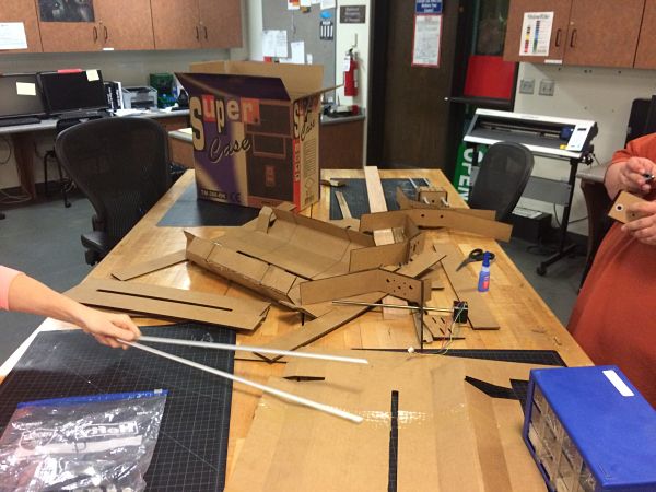
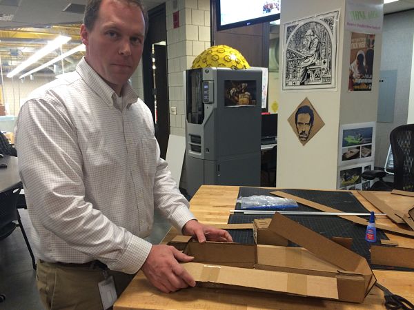
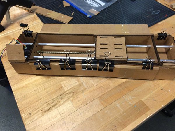
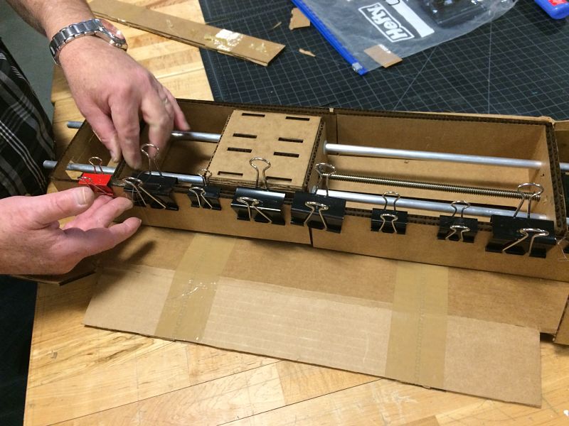
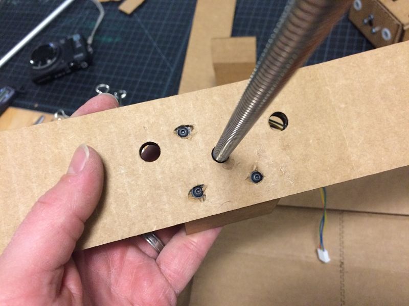
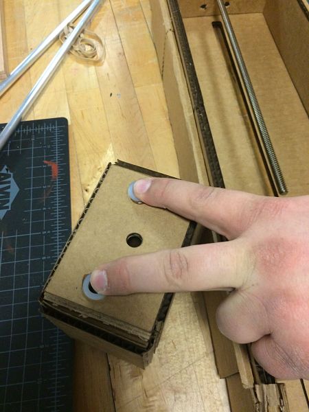
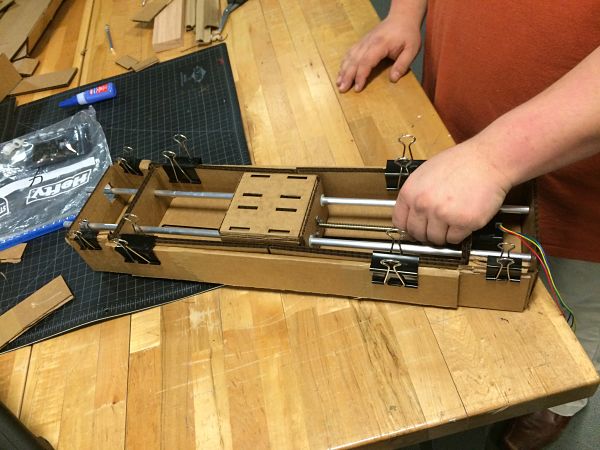
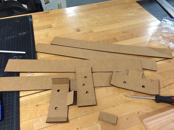
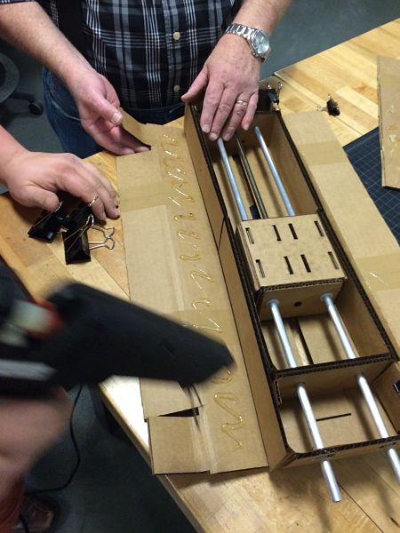
Photos of the assembly of the boxes.
I then complied all the photos, movies, and built our class project page. I created the Class Slide, Class Video and Class Webpage.
Presentation Slide Class Video Class Webpage