what is the deadline? How much
time do I have left?
The deadline for my project is Monday June 20th,
I will have 5 days from the next global meeting on Wednesday the 15th.
what tasks have been completed,
and what tasks remain?
Task | Estimated Due Date | Completed |
Make H-Bridge for out put week for pump testing |
4/27/16 |
yes |
3D print pump |
3/21/16 |
yes |
Test Pump designs |
4/1/16 |
yes |
Acquire Parts |
6/2/16 |
yes |
Design PCB |
6/4/16 |
yes |
Create PCB and Populate |
6/6/16 |
yes |
Solder wires for pumps and Potentiometers |
6/6/16 |
yes |
Create wiring harness |
6/7/16 |
yes |
Design Cup Holder |
6/10/16 |
yes |
Write Code |
6/9/16 |
yes |
Test Code and evaluate timing |
6/15/16 |
In Process |
Presentation |
6/20/16 |
Upcoming |
Final Documentation |
6/28/16 |
In Process |
Right now I have to
finish up the stand and work on a few final things like buttons and final
labeling
how will I complete the
remaining tasks in time?
On Monday June 13 I will try to use the 3d
printer to print out my button parts. After that it is just final assembly and
testing.
what has worked?
So far the thing that have worked is the circuit boards and the
code I wrote for it and the stand and case design.
what hasn't?
What hasn’t work the main thing was the pump I
designed. It would not run as good as I
would have liked. I did try playing with
the pump rollers and tube but I ended up having to buy some small pumps. The other thing that did not work the first
time was the holes in my case for the buttons they were off about a quarter of
an inch.
what questions still need to be
resolved?
The questions that still need to be answered is the button and the
final placement of the dispenser head.
what have you learned?
I have learned a lot of during the past 18 weeks. One of the biggest skills that I learned is how to apply time management with how and when parts come in and to try to do a spiral type project development. During the 18 weeks i would work on pieces of my final project when not doing the tasks for the week to try to make sure my final was moving along and if any issues came up i had time to fix them. When deciding on the scope of the project I learn not to make the final project too big but have the ability to add and improve it. One area that I struggled with was the computer aided design files be it 2d or 3d. I definitely feel more comfortable with 3d modeling but still would need a lot of help to do anything complex.
For my final project I wanted to
create a drink dispensing machine. While
doing research to see what has been done before I did find a lot of designs
that varied in construction and how it worked.
There is also some commercial products for bars and home use but have
extremely high cost.
The final project is a large task and i started working on it early in
the class. One of the first things that I wanted to try and
create is the pump, I started having Karen help me very early on to
make sure my idea would work. Once the pump was figured out I knew I
was going to need some type of integrated circuit to interface with
what ever motor I was going to use on the pump because it is easy to
find 12v DC motors but harder to find 5v DC pumps and the micro may not
have enough current capabilities to power the 5v pump.
For my project I looked into many
different pumps to be able to meter liquids and found many including diaphragm,
impeller, and peristaltic. To make my
decision there where a few factors that I considered. The first was how easy it is to clean and the
other was flow rate. The first factor I
feel is the most importance since you will be running different liquids and
need to clean it when done or switching liquids. When looking at the pumps the diaphragm and
impeller pumps had very high flow rates but are not the easiest to be cleaned
and they have to be made of sterile food grade parts which are expensive to buy
and hard to create in the fab lab. I
decided to go with the peristaltic type pump because the liquid never touches
the pump parts making cleaning very easy and the ability to keep thing
sterile. The down side of this pump is
that the flow rates are very slow. These
pumps are used in IV pump for the medical industry so they can meter a very
exact amount.
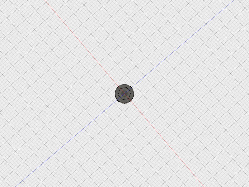
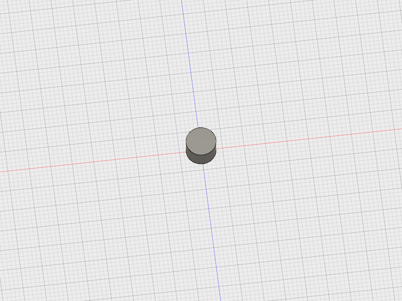
To start Karen helped me design a
pump based on multiple designs online to scale up the pump to get a higher flow
rate.
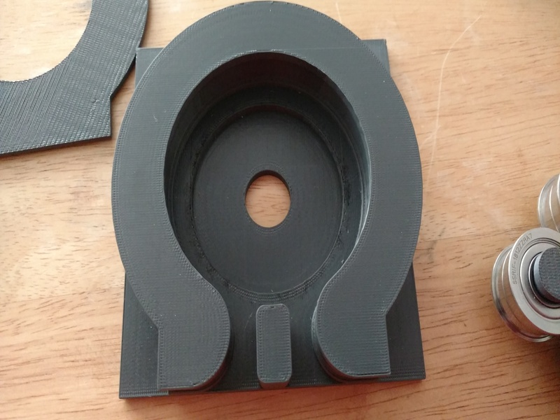
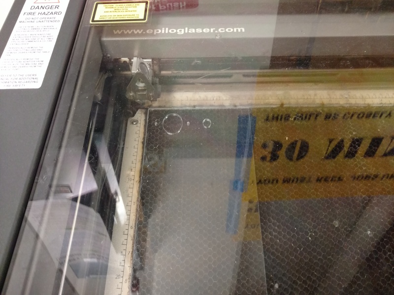
Below is the pictures of the pump printed on the Dimension 1200es
printer, it took over 12 cubic inches of material to print and coasted
almost $60. I had to order some silicone peristaltic pump tube
from Mc Master Carr to see if it would work.

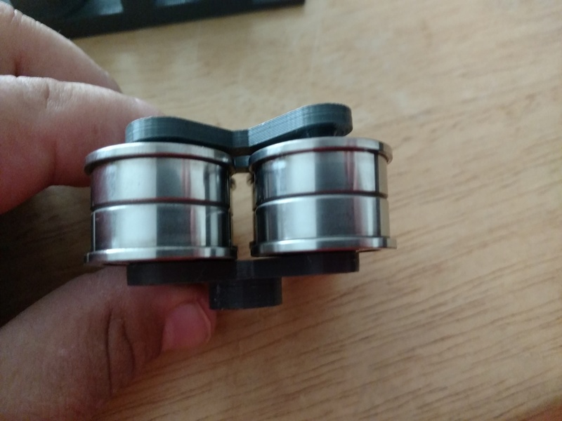

This pump did not work right when
the tube I got was placed in. The tube
is $5 a foot and specially made for these type of pumps. The rollers were too tight so I used are
cheaper 3d printer to make some rollers.
I used our Makergear printer using PLA to make various rollers in
different shapes and diameters to try and make the pump work. I
printed these out during the weeks we were doing other projects trying
to continue the spiral development.

In the
end the pump did not work
right. They would begin to pull up water but either the motor
needed to be faster or the pump needed to be redesigned. The pump I was
trying to make cost over $60 to print on the 3d printer, so I found
some pumps from
adafruit they cost $25 a piece which is much more affordable and they
work very well other then they have a slow
flow rate. I would have liked to made
my own pumps and may go back and do that once I can learn some more on how
those pump work and are modeled.
For my
final project I knew that I was going to need a DC motor so for the output week
I made a board with an H-Bridge motor driver integrated circuit. In that week I learn how to use it and
control it with Pulse width modulation and just running it at full speed.
Before I created my final board I used the one I made in the output week and modified it to add a 10 turn potentiometer that I could use to adjust a delay in my code for the level in the glass.
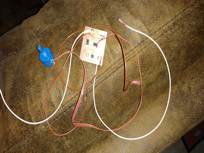
Once I was able to use that output board for testing it was time I created the board for my final. I was going to create one board with two h-bridges and all of the support inputs but it started to become very hard to route on a single side and I did not want to make a dual layer board because it is difficult to have the via holes aligned if you do not flip and have a good reference and adding the wires to connect the top and bottom can be hard. So I decided to make one board for one pump that way I can add more and network them in at a future date. To create my boards for the final I used eagle to make them. I did the same process that we have done in the previous weeks like adding all the parts i needed to the schematic and then switched to the board layout part to create the board. I used a ground plane on my board to make the routing easier and it also reduces the machining time for the board production.

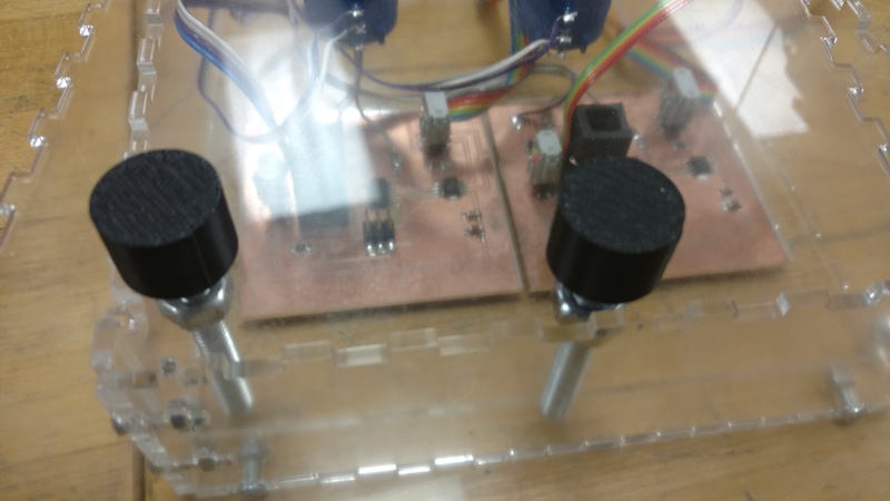
Below are a picture of the finished and populated boards in the case getting ready to do testing.

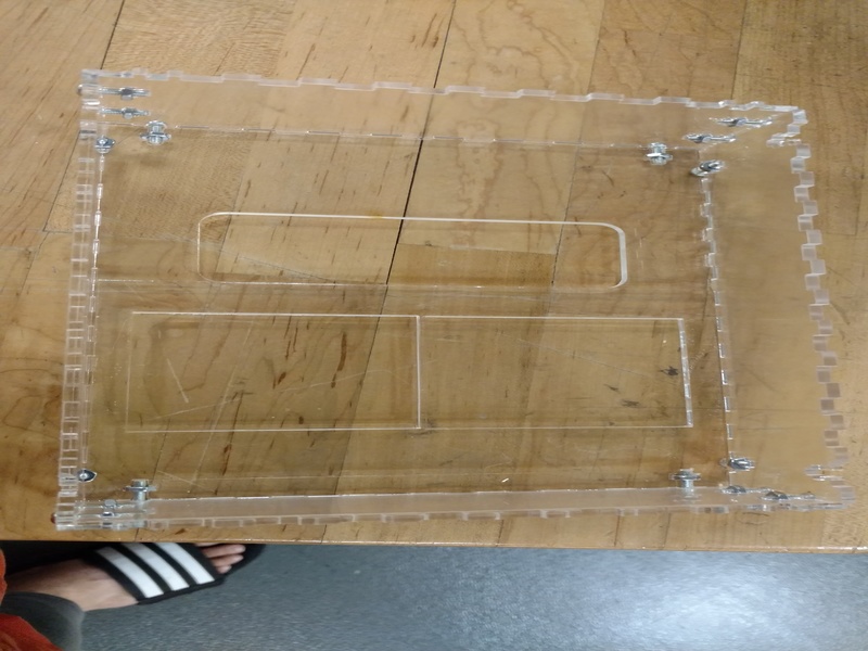
When
thinking about what to make the stand and case out of it was between a
nice oak
plywood or acrylic and I decide to use acrylic for the ease of clean up
and if any
liquids get spilled on it the acrylic will not de laminate like the
plywood would. The only down side is that the only acrylic we had
in the lab was clear so it dose not look as nice as the wood would
have.
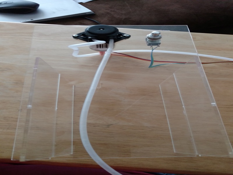
Once the fit was good for the pump and the button I created some slots to be able to add another piece to act as legs this worked great and I have the ability to take it apart for easy transport.
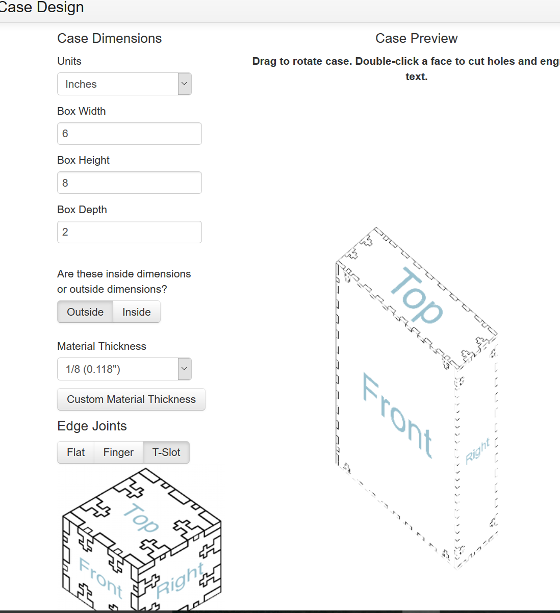
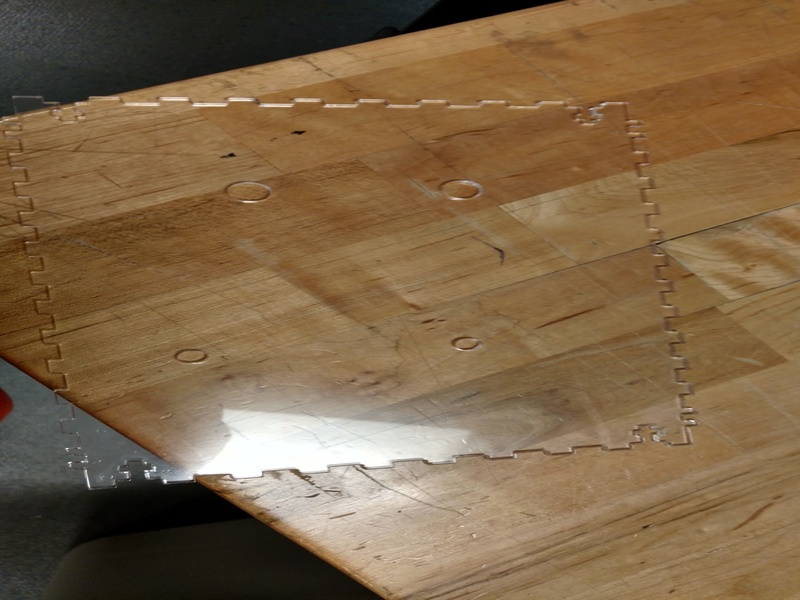
Once I has the design file from the website I used corel to add holes for the buttons and the pots that will adjust the level. The first top piece that I cut the laser did not go thru all the way and my holes for the buttons were off about a quarter of an inch so I had to recut the top.
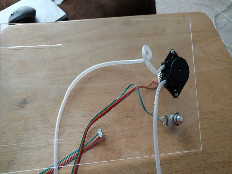
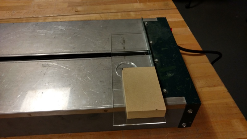
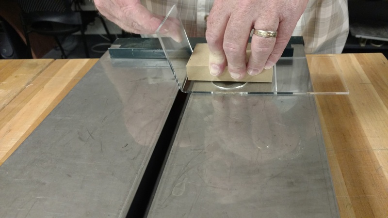
For the pumps I had to make a quick change to have amounting
place for the output hose and then I also I created a shot glass holder. Tim helped me bend the acrylic since I never
have done it before.

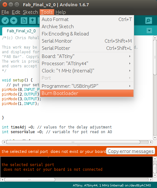
For my final project I decide to use the Arduino IDE and attiny cores plugin from High-Low Tech research group from MIT.
Once the plugin was installed I created a new sketch and had to choose the attiny 44 and a few options like what speed and the programmer. Once that was complete I used the burn bootloader to write the fuses and then started the code.
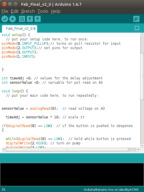
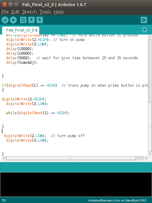
The code above is the beginning of the code for my project. Each board uses the same code. In the setup function I set the pins that I need to be either input or outputs. I use a one input with the internal pull up resistors and one with an external pull up resistor. After I set up the pins I added a couple of variables read the analog input and to be a timer adjust value.
To make the button and button sleeve I used Autodesk’s fusion 360.

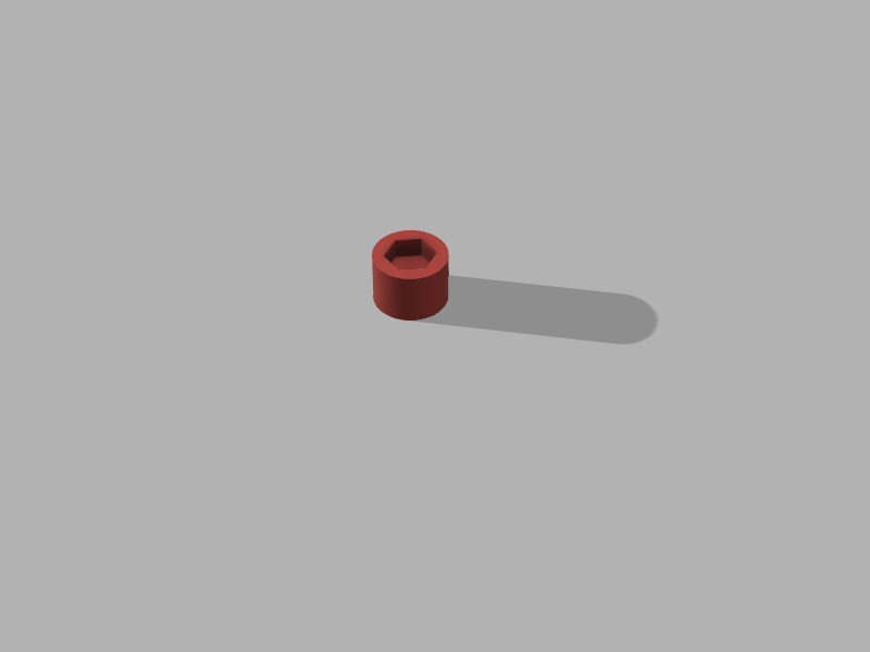
This is the sleeve.

It was a bit too long so I had to cut it but I wanted to make sure it would fit so it’s better to be able to cut off some then add some.