This week
assignment was to create a board that used a microcontroller on it and
some
form of output device. I
decide to use
the H-Bridge for a DC motor since I will be using one on my final
project. The
H-Bridge is a very nice device because it
allows for a dc motor to be reversed.
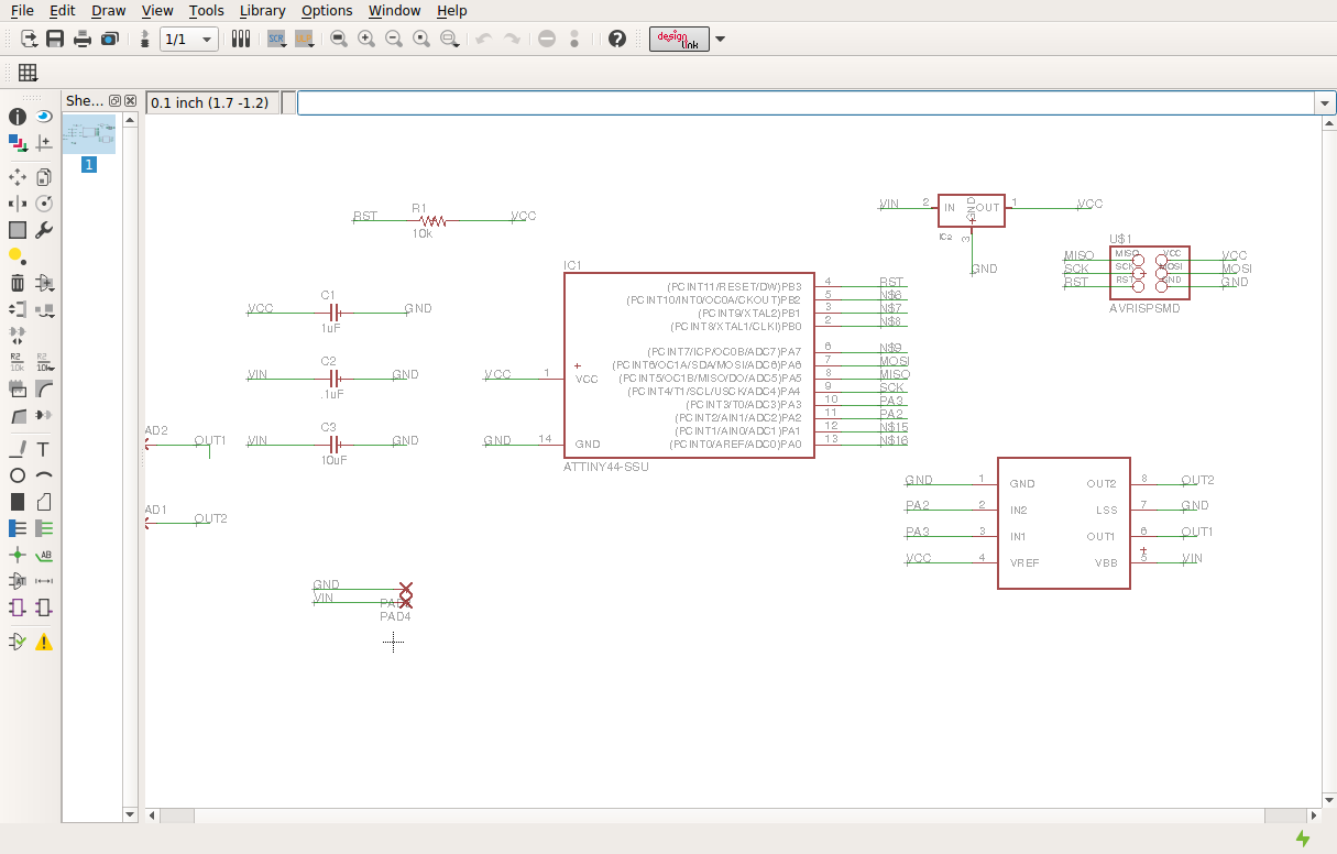
To create the board this week I studied Neil’s design for the H-Bridge and read over the data sheet for the chip. I decided to use an attiny 44 for future use on my final project it has more inputs available. The chip that I used was the A4953 full bridge PWM motor control IC. This chip allows for up to 2 amps of current draw and to be powered by up to 40 volts. To use this IC you need to send a pulse width modulated signal to the IN1 or IN2 pins to tell the motor to go forward or reverse. To create the board I first started out in eagle by placing all of the components I will need then added wires and labels to connect them. Once all the connections were made I switch over to the board side just like in previous weeks.

After the board
layout was completed I exported it to a
Geber file so it could be cut out on my LPFK S63 rapid PCB
machine. The tools sizes i used on teh machine were 2mm
contour router bit for cutting out the board, 2mm drill for the start
hole for routing, .2-.3 mm universal milling bit and 2mm endmill.
The board could be cut with the 1/64 endmill for the traces and the
1/32 endmill for the outline cutting using the fab modules and the
Roland mill.
To make sure the board was working I used Neil’s code that ran the motor at different speed using a form of pulse width modulation. It worked ok but I don’t need that right now I wanted my pump to run at full speed for about 30 seconds. So once I figured out that it was as simple as setting a pin high and then waiting x amount of time I modified the code to run for 30 seconds and then turn off and wait for 10 more seconds.

The above code sets IN2 and IN1 name to correspond to a port in this case PA2 and PA3.
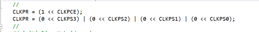
This code set the clock to help with the delay function.

In this section
it is the main while loop that clears IN1
and set IN2 to high to make the motor run the next three lines run a
delay for
10000 milliseconds or 10 seconds each for a total of 30 seconds. The next two lines clear
both the inputs on
the motor IC to turn off the motor and then waits for 10 seconds.
This is the
first step for my final project because I want
to dispense a specific amount of liquid in this case about one jigger
or about
1.5 US fluid ounces.
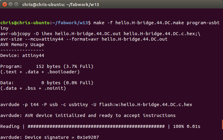
To send the
program to the micro I used the make file on the
fab academy’s website to compile my c file and then upload it via the
usbtiny
that I made earlier in the class.

Below is a
video of the pump running for 30 seconds and then
stopping.
VID_20160503_132248172 from chris rohal on Vimeo.