

PART-1 distance sensor FOR FINAL PROJECT
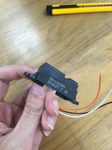
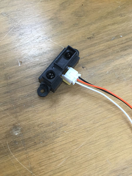
I want to use this distance sensor to make a cmagzine. In my final project there is a little magnet iron ball-ejector and a magazine, remain iron ball could be inductived by a distance sensor in the magzine, then projected on a LED screen.
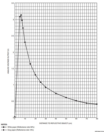
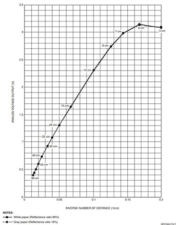
SHARP 2Y0A data parameters
FEATURES
• Digital Output
• LED Pulse Cycle Duration: 32 ms
• Range: 10 to 80 cm
• Typical response time: 39 ms
• Typical start up delay: 44 ms
• Average Current Consumption: 30 mA
• Detection Area Diameter @ 80 cm: 12 cm
programming
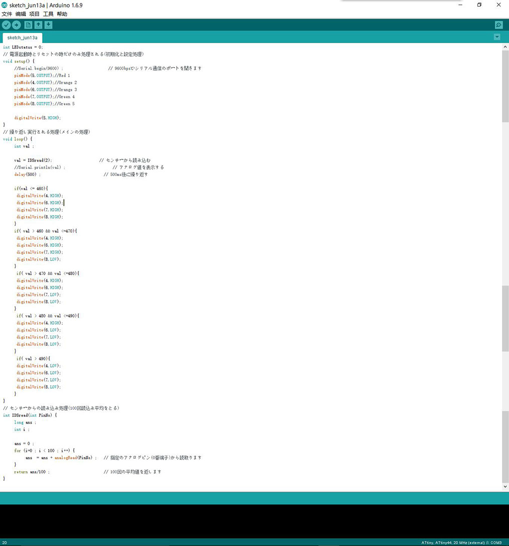
At first, I put the distance sensor in the magazine, then tested the sensor's reading, the value is 490-460. When the object nearest by the sensor, the value is 460. when the object is farthest from the sensor, the value is 490.
Because I want to use 5 LED to represent the remaining bullets. I divide the value into 5 groups: val<= 460, val> 460, val> 470, val> 480, val> 490. Then, set the LED' working condition for each group.
if(val <= 460)
digitalWrite(4,HIGH);
digitalWrite(6,HIGH);
digitalWrite(7,HIGH);
digitalWrite(8,HIGH);
f( val > 460 && val <=470)
digitalWrite(4,HIGH);
digitalWrite(6,HIGH);
digitalWrite(7,HIGH);
digitalWrite(8,LOW);
if( val > 470 && val <=480)
digitalWrite(4,HIGH);
digitalWrite(6,HIGH);
digitalWrite(7,LOW);
digitalWrite(8,LOW);
if( val > 480 && val <=490)
digitalWrite(4,HIGH);
digitalWrite(6,LOW);
digitalWrite(7,LOW);
digitalWrite(8,LOW);
if( val > 490)
digitalWrite(4,LOW);
digitalWrite(6,LOW);
digitalWrite(7,LOW);
digitalWrite(8,LOW);
So by this program the number of the led will reflect the left iron balls, full magazine with five LEDs and if the magazine is empty, there is only one red LED left.
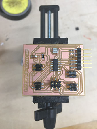
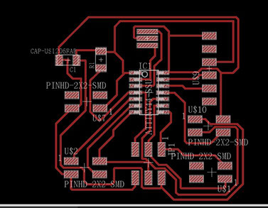
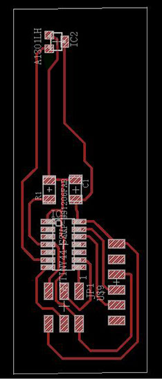
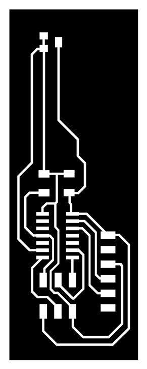
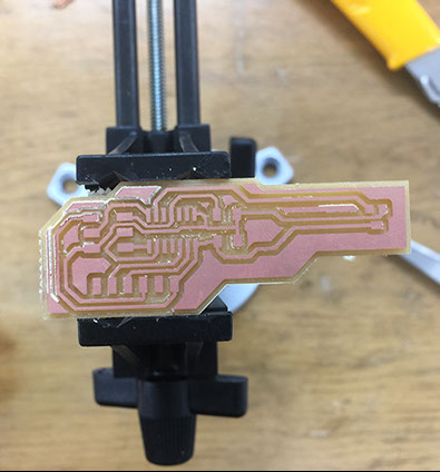
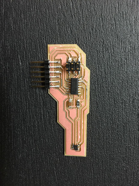
Circuit board
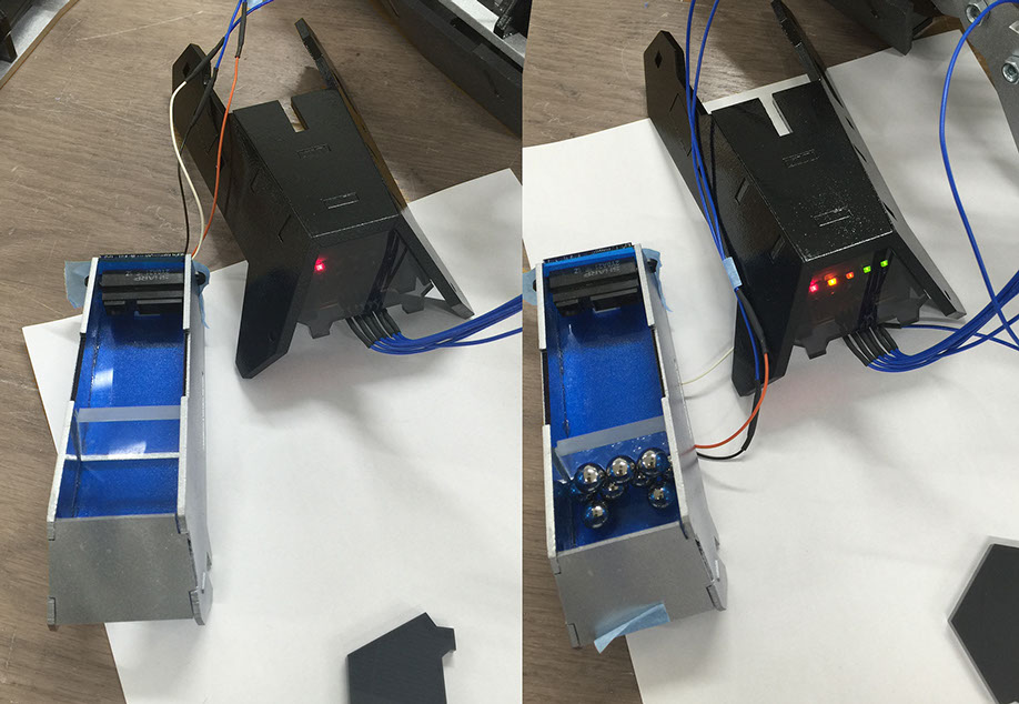
I made a transparent acrylic magazine. But the test result is not good, in order to solve this problem, I painted the magazine. Now it can work properly.

PART-2 magnetic field
Because the11th week (input devices) and 13th week (output devices) were all worked for my final project, so they were all use the same board. This time I‘ll make a magnetic field and design a new board.
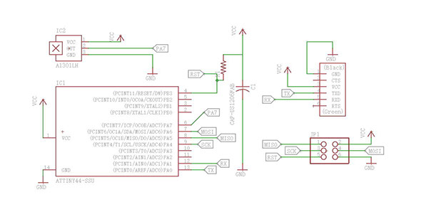
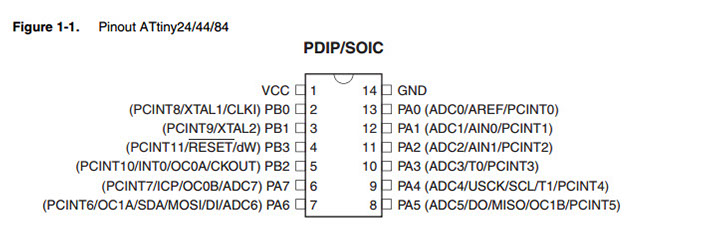
I use the Attiny44 to make the board, and use the PIN-PA7 as the magnetic field's out.


Operation sequence
- Prepare the tools .
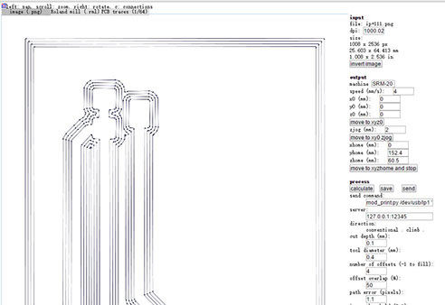
- Turn on the power and link SRM-20 to the computer.
- Open the SRM-20' driver program.
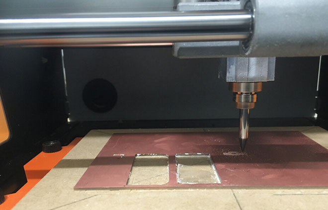
- Fixed the board on the wood board with the 3M double side glue.
- Set the XY axis first and put the 0.4mm drill in.
- Set the Z axis, adjust the height of drill then fixed it.
- Load data and start to work.
- When the traces cut is finished set the 0.8mm drill for outline cutting.

-crop-u20435.jpg)
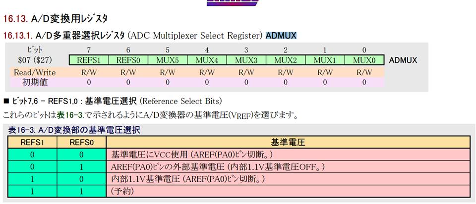
Neils Program is for Attiny45 if I want to use it, I need to change it for Attiny44. According to the Attiny44's data sheet, there is 8it in the ADMUX: REFS1,REFS0,MUX5,MUX4,MUX3,MUX2,MUX1,MUX0. I can set the voltage by changing the number, because I use PA7(000111).
so I changed:
// init A/D
//
ADMUX = (0 << REFS2) | (0 << REFS1) | (0 << REFS0) // Vcc ref
| (0 << ADLAR) // right adjust
| (0 << MUX3) | (0 << MUX2) | (1 << MUX1) | (0 << MUX0); // ADC4
ADCSRA = (1 << ADEN) // enable
| (1 << ADPS2) | (1 << ADPS1) | (1 << ADPS0); // prescaler /128
to
// init A/D
//
ADMUX = (0 << REFS1) | (0 << REFS0) // Vcc ref
| (0 << MUX5)| (0 << MUX4)| (0 << MUX3) | (1 << MUX2) | (1 << MUX1) | (1 << MUX0); // ADC7
ADCSRA = (1 << ADEN) // enable
| (1 << ADPS2) | (1 << ADPS1) | (1 << ADPS0); // prescaler /128
.jpg)
Analysis of Neils program
for (count = 0; count < nsamples; ++count) {
//
// initiate conversion
//
ADCSRA |= (1 << ADSC);
//
// wait for completion
//
while (ADCSRA & (1 << ADSC))
;
//
// add result
//
accum += ADC;
}
//
nsamples=100times measurements
It begins with ADSC: ''1'', when the ADSC: ''0'', It will send the results to ADC
Will be waiting for the end of the measurements at while (ADCSRA & (1 << ADSC))
When the measurements is finished it will add to accum
By sending the 1-4 number, so that the data is more clear.
Serial communication can only send a 1byte, so it should be sent three times
// send framing
//
put_char(&serial_port, serial_pin_out, 1);
char_delay();
put_char(&serial_port, serial_pin_out, 2);
char_delay();
put_char(&serial_port, serial_pin_out, 3);
char_delay();
put_char(&serial_port, serial_pin_out, 4);
char_delay();
//
// send result
//
put_char(&serial_port, serial_pin_out, (accum & 255));
char_delay();
put_char(&serial_port, serial_pin_out, ((accum >> 8) & 255));
char_delay();
put_char(&serial_port, serial_pin_out, ((accum >> 16) & 255));
char_delay();
PROJECT=hello.mag.45
SOURCES=$(PROJECT).c
MMCU=attiny44
F_CPU = 8000000
CFLAGS=-mmcu=$(MMCU) -Wall -Os -DF_CPU=$(F_CPU)
$(PROJECT).hex: $(PROJECT).out
avr-objcopy -O ihex $(PROJECT).out $(PROJECT).c.hex;\
avr-size --mcu=$(MMCU) --format=avr $(PROJECT).out
$(PROJECT).out: $(SOURCES)
avr-gcc $(CFLAGS) -I./ -o $(PROJECT).out $(SOURCES)
program-bsd: $(PROJECT).hex
avrdude -p t44 -c bsd -U flash:w:$(PROJECT).c.hex
program-dasa: $(PROJECT).hex
avrdude -p t44 -P /dev/ttyUSB0 -c dasa -U flash:w:$(PROJECT).c.hex
program-avrisp2: $(PROJECT).hex
avrdude -p t44 -P usb -c avrisp2 -U flash:w:$(PROJECT).c.hex
program-avrisp2-fuses: $(PROJECT).hex
avrdude -p t44 -P usb -c avrisp2 -U lfuse:w:0x5E:m
program-usbtiny: $(PROJECT).hex
avrdude -p t44 -P usb -c usbtiny -U flash:w:$(PROJECT).c.hex
program-usbtiny-fuses: $(PROJECT).hex
avrdude -p t44 -P usb -c usbtiny -U lfuse:w:0x5E:m
program-dragon: $(PROJECT).hex
avrdude -p t44 -P usb -c dragon_isp -U flash:w:$(PROJECT).c.hex
make file:
Cygwin64' command:
make -f XXXXXXXXXX.make
sudo make -f XXXXXXXXXXXX.make program-usbtiny-fuses
sudo make -f XXXXXXXXXXXX.make program-usbtiny
Use Neils Python Program.


