11. Input devices
In the week6 Electronics production, I made a board which could be attached multiple different sensor and actuator. Therefore, in this week, I try to make a sensor board which could be connected with my board.
First, I downloaded temperature example file.
This example is attiny45, however my board uses attiny44. Thus, I redesigned a board and program file for attiny44.
11-1. Designing temperature sensor board
I redesign the board refering to example. I added some electronics parts from eagles library.
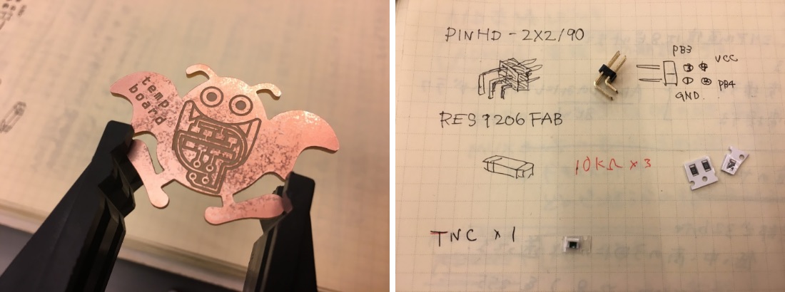
PARTS : PINHD 2×2/90 and RES1206FAB×4(10k ×3 and TNC)
And I connected each parts with wires and exported png file.
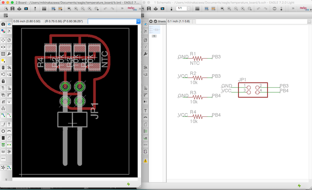 Download : temp.brd・temp.sch
Next I imported the png in Adobe illustrator.(because I want to make board “Drakee” which is a monster of japanese famous game DRAGON QUEST. )
I designed drakee outline and assembled circuit and it. I exported three png files : outline, traces, holes.
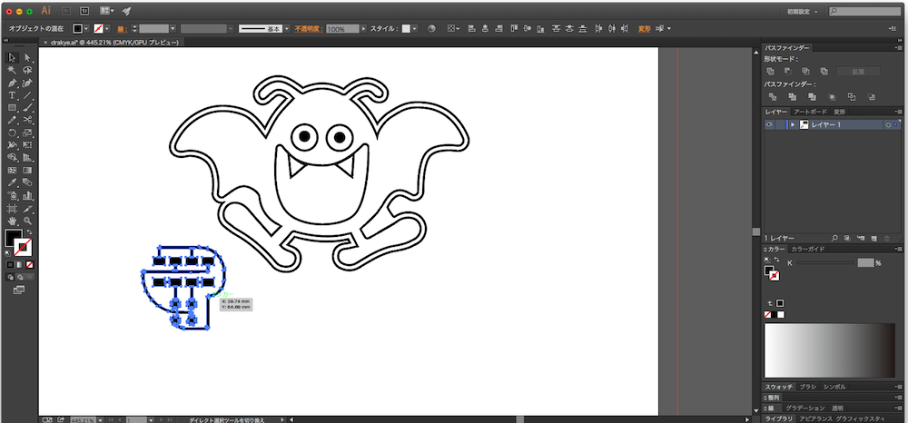
 Download : outline.png・traces.png・text_offset-1.png
11-2. Making PCB board
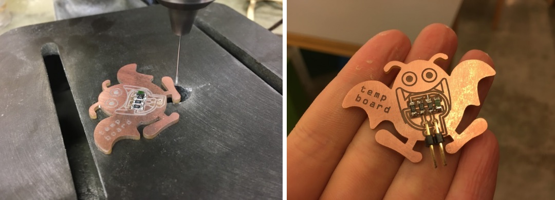
After making g-code files with fabmodules, I milled the board. I used the machine kitmill cip100 which is for making circuit only. Next Soldering board.
While soldering, I noticed that I had a mistake.
2*2 pinheader holes is too small. Thus, I drilled more bigger holes with drilling machine.
11-3. writing temperature sensoring program
Refering to example temp board, I wrote program like below.
        #include
        #include

        #define output(directions,pin) (directions |= pin)
         // set port direction for output
        #define set(port,pin) (port |= pin)
         // set port pin
        #define clear(port,pin) (port &= (~pin))
        // clear port pin
        #define pin_test(pins,pin) (pins & pin)
         // test for port pin
        #define bit_test(byte,bit) (byte & (1 << bit)) // test for bit set
        #define bit_delay_time 102
        // bit delay for 9600 with overhead
        #define bit_delay() _delay_us(bit_delay_time)
        // RS232 bit delay
        #define half_bit_delay() _delay_us(bit_delay_time/2)
        // RS232 half bit delay
        #define char_delay() _delay_ms(10)
        // char delay

        #define serial_port PORTA
        #define serial_direction DDRA
        #define serial_pin_out (1 << PA1) //// シリアル送信ピンRX

        void put_char(volatile unsigned char *port, unsigned char pin, char txchar) {

           clear(*port,pin);
           bit_delay();

           if bit_test(txchar,0)
              set(*port,pin);
           else
              clear(*port,pin);
           bit_delay();
           if bit_test(txchar,1)
              set(*port,pin);
           else
              clear(*port,pin);
           bit_delay();
           if bit_test(txchar,2)
              set(*port,pin);
           else
              clear(*port,pin);
           bit_delay();
           if bit_test(txchar,3)
              set(*port,pin);
           else
              clear(*port,pin);
           bit_delay();
           if bit_test(txchar,4)
              set(*port,pin);
           else
              clear(*port,pin);
           bit_delay();
           if bit_test(txchar,5)
              set(*port,pin);
           else
              clear(*port,pin);
           bit_delay();
           if bit_test(txchar,6)
              set(*port,pin);
           else
              clear(*port,pin);
           bit_delay();
           if bit_test(txchar,7)
              set(*port,pin);
           else
              clear(*port,pin);
           bit_delay();

           set(*port,pin);
           bit_delay();

           bit_delay();
           }

        int main(void) {

           static char chr;

           CLKPR = (1 << CLKPCE);
           CLKPR = (0 << CLKPS3) | (0 << CLKPS2) | (0 << CLKPS1) | (0 << CLKPS0);

           set(serial_port, serial_pin_out);
           output(serial_direction, serial_pin_out);

           ADMUX = (0 << REFS1) | (0 << REFS0) //  attiny44はrefs1,refs0のみ
              //| (0 << ADLAR) // right adjust
            | (0 << MUX5)  | (1 << MUX4)| (0 << MUX3) | (0 << MUX2) | (0 << MUX1) | (1 << MUX0);
            // 20(PA2-PA3) A/d変換の表をみて記入する。センシングするピン指定をここで行う
           ADCSRA = (1 << ADEN) // 1が動作許可
              | (1 << ADPS2) | (1 << ADPS1) | (1 << ADPS0); // 分周比CK/128 = 111
           ADCSRB = (1 << BIN); // bipolar mode

           while (1) {

              put_char(&serial_port, serial_pin_out, 1);
              char_delay();
              put_char(&serial_port, serial_pin_out, 2);
              char_delay();
              put_char(&serial_port, serial_pin_out, 3);
              char_delay();
              put_char(&serial_port, serial_pin_out, 4);
              char_delay();

              ADCSRA |= (1 << ADSC);

              while (ADCSRA & (1 << ADSC))
                 ;

              chr = ADCL;
              put_char(&serial_port, serial_pin_out, chr);
              char_delay();
              chr = ADCH;
              put_char(&serial_port, serial_pin_out, chr);
              char_delay();
              }
           }
During make program, I had some trobles. I noticed that Data sheet is very important !!!
in the setting MDMUX,
・ Attiny 45 has REFS 0-2 , but Attiny44 has REFS 0-1 only. I should delete “0 << REFS2”.
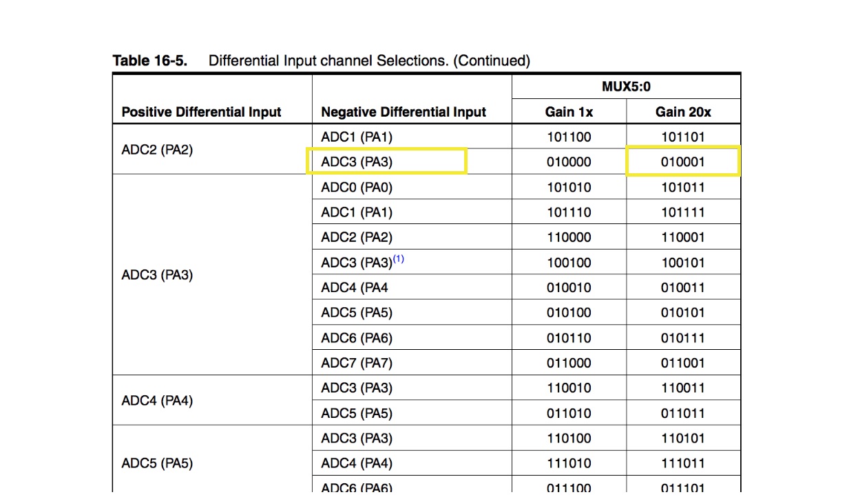
・My board uses pin PA3 and PA2 as sensor input. Example board uses pin PB3 and PB4.
I changed line 119, MUX5~0. Refer to datasheet, [ (PA2-PA3)×20] is [ MUX5~0:010001] .
11-5. Writing a program in Drakee board
I connected each boards like this.
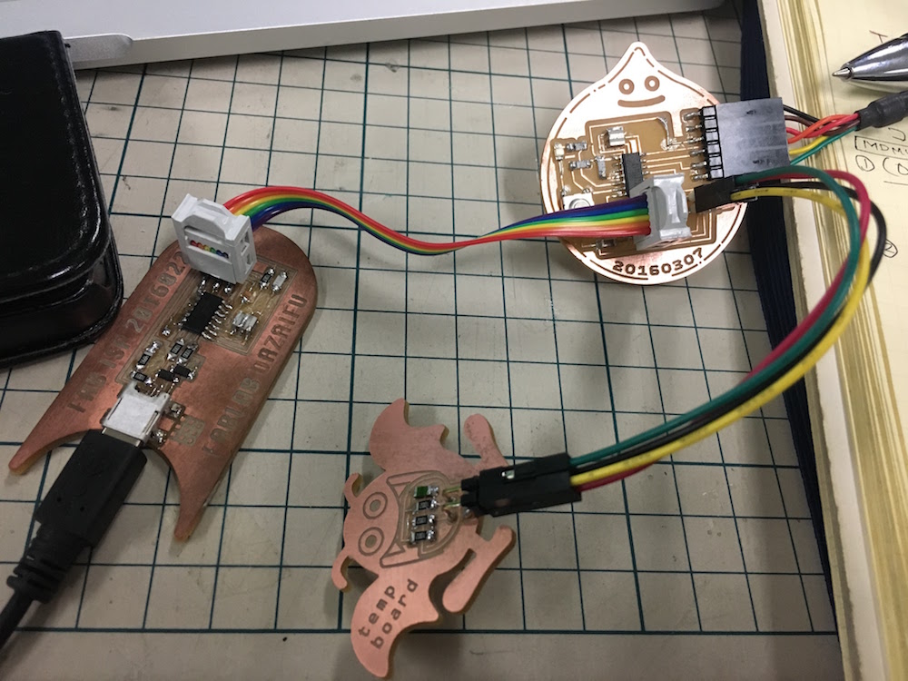
PC -- [usb cable] -- FAB ISP -- [2×3 ribbon cable] -- Slyme attiny44 board
[[slyme attiny44 board]] -- [2×2 ribbon cable] -- Drakee board(Sensor board)
[[slyme attiny44 board]] -- [FTDI cable] -- PC
I wrote make file like below.
        PROJECT=temp
        SOURCES=$(PROJECT).c
        MMCU=attiny44
        F_CPU = 20000000

        CFLAGS=-mmcu=$(MMCU) -Wall -Os -DF_CPU=$(F_CPU)

        $(PROJECT).hex: $(PROJECT).out
            avr-objcopy -O ihex $(PROJECT).out $(PROJECT).c.hex;\
            avr-size --mcu=$(MMCU) --format=avr $(PROJECT).out

        $(PROJECT).out: $(SOURCES)
            avr-gcc $(CFLAGS) -I./ -o $(PROJECT).out $(SOURCES)

        program-bsd: $(PROJECT).hex
            avrdude -p t44 -c bsd -U flash:w:$(PROJECT).c.hex

        program-dasa: $(PROJECT).hex
            avrdude -p t44 -P /dev/ttyUSB0 -c dasa -U flash:w:$(PROJECT).c.hex

        program-avrisp2: $(PROJECT).hex
            avrdude -p t44 -P usb -c avrisp2 -U flash:w:$(PROJECT).c.hex

        program-usbtiny: $(PROJECT).hex
            avrdude -p t44 -P usb -c usbtiny -U flash:w:$(PROJECT).c.hex

        program-dragon: $(PROJECT).hex
            avrdude -p t44 -P usb -c dragon_isp -U flash:w:$(PROJECT).c.hex
and typed below command in terminal.
        cd ~/Desktop/program/temp
        make -f temp.make
        sudo make -f temp.make program-usbtiny //writing program
        python temp.py /dev/tty.usbserial-FTGO00D8 // open serial monitor
Result.