week 13 | 2016/04/27 - 2016/05/04 | output devices
18
Let there be light!
xx
19
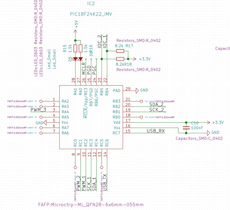
To fulfill my assignment for this week, I decided to program a 3 channel PWM for my input devices PCB - which was originally planned to do these to assignments. This PCB is also one part for my final project - so, this work was helpful to finish my final project.
20
21
The startup code and timer configuration was the same like my old one for the fabpic, but to configurate the PWM I used the Datasheet and read the PWM configuration part.
22
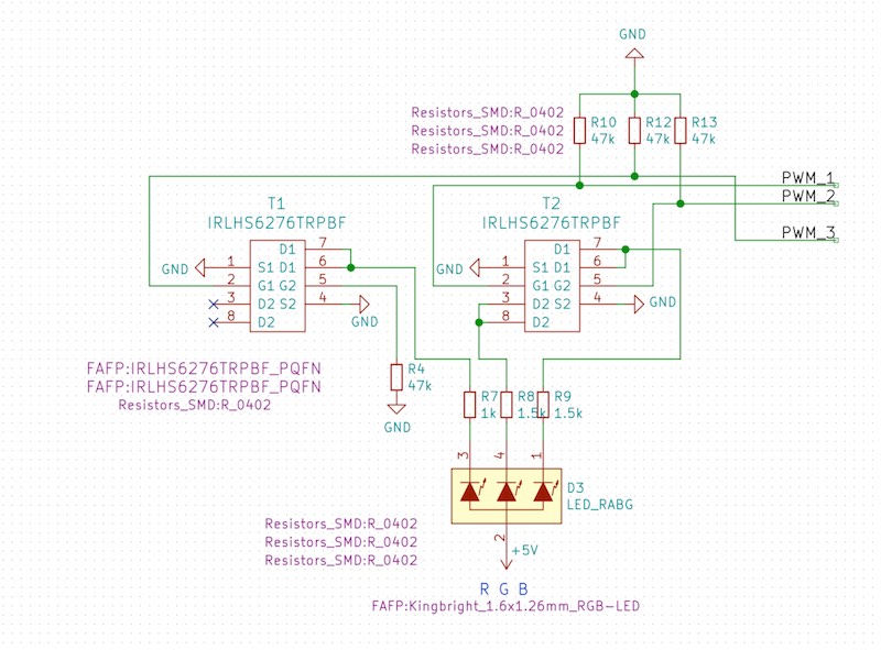
As LED I used a very nice, small and bright 1.6x1.26mm RGB LED from Kingbright. All 3 colors are driven through a MOSFET and a resistor from 5V.
23
To check if the PWM works correctly, I connected my PicoScope to 2 of my 3 PWM channels. This looks quite nice and works...
24
25
As you can see in the upper GIF, my code and the LEDs work :) - Now I only have to redraw the outline to fit this PCB onto my skaterdolly bogie (and add a connector to communicate to the mainboard).
26
Here, I'll show you the main functions. The PCB contains a simple, which drives a RGB LED through 3 MOSFETs by PWM. The design is a very rough prototype, which even was a development for my final project, so the PCB is not that beautiful.
27
28

This work by Daniel Bruns is licensed under a Creative Commons Attribution-NonCommercial-ShareAlike 4.0 International License.