Assignment #13 Output Devices
Introduction
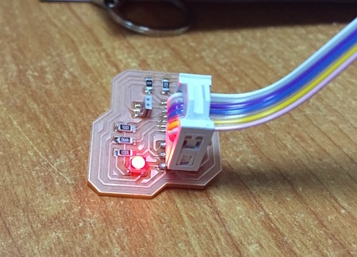
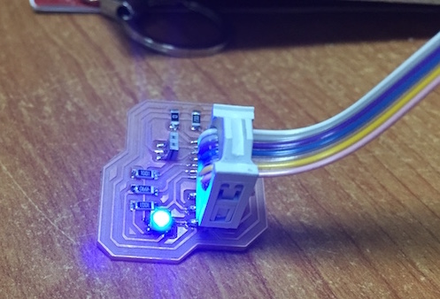
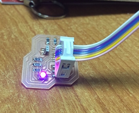
I choose to use RGB SMD LED as an output device, and to test it while emitting variable light colors
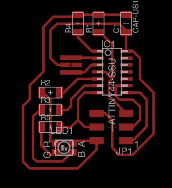
- I used eagle as usual to draw the schematics and the PCB, at the beginning I connect the common Anode of the RGB led with the GND, but I correct this one later, unfortunately after I made the first board :D
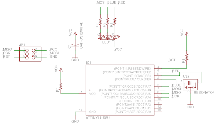
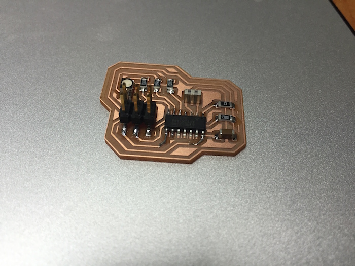
- Here it is after soldering the components, take care to choose a PWM pins of the RGB LED so you can control the LED color degrees, this link will help you a lot it that
Download File

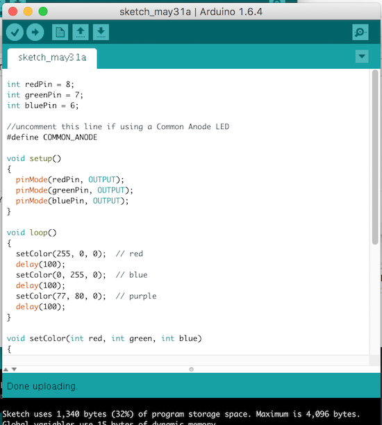
- Here is the Arduino code i wrote to control the RGB LED, I didn't want to over complicate it, you can change the LED colors by changing the color values im the void loop, try different values and have some fun :D
int redPin = 8;
int greenPin = 7;
int bluePin = 6;

//uncomment this line if using a Common Anode LED
#define COMMON_ANODE

void setup()
{
  pinMode(redPin, OUTPUT);
  pinMode(greenPin, OUTPUT);
  pinMode(bluePin, OUTPUT);
}

void loop()
{
  setColor(255, 0, 0);  // red
  delay(100);
  setColor(0, 255, 0);  // blue
  delay(100);
  setColor(77, 80, 0);  // purple
  delay(100);
}

void setColor(int red, int green, int blue)
{
    red = 255 - red;
    green = 255 - green;
    blue = 255 - blue;
  analogWrite(redPin, red);
  analogWrite(greenPin, green);
  analogWrite(bluePin, blue);
}
- And here it is :D