Final Project
Introduction
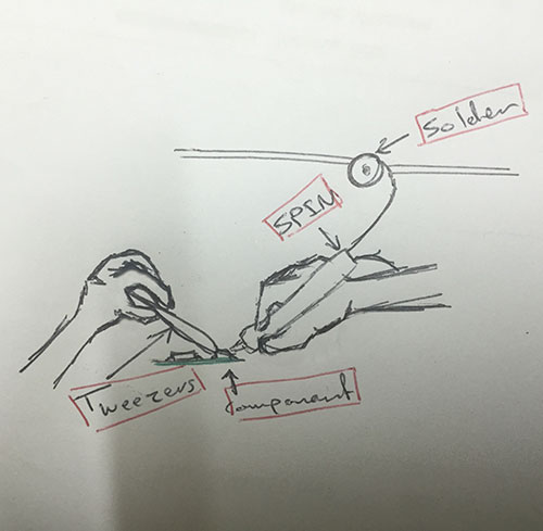
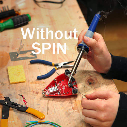
One of the most repeated actions that any maker do in his life is Soldering, some improvement have happened to the soldering kit through time, but all of them need the user to use both of his hands, rendering his ability to easily hold the component in it's place..
This obstacle hit me when I first learn soldering which made me start thinking in a way to make me control both of the solder and the soldering iron with the same hand, giving me the ability to freely hold the component with the other one..
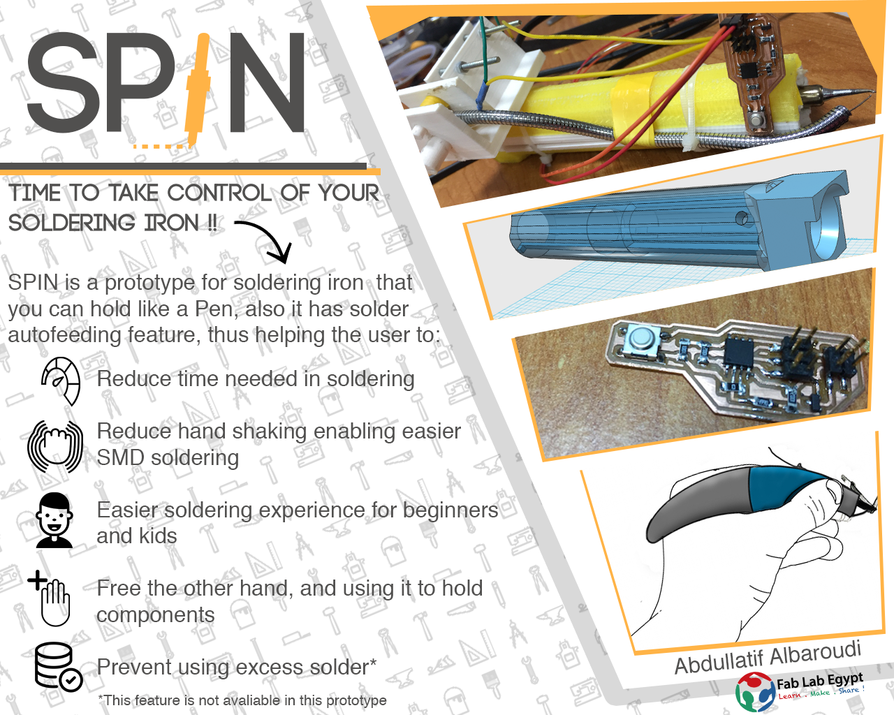
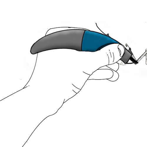
My final project "which i call: SPIN" will be making a soldering iron that can be hold like a pen while it get fed with solder automatically when pressing the feeding button with your index finger...
- some of SPIN features:
- It will give you the ability to use your other hand while soldering with the first one.
- It will make the soldering easier for beginners and for the kids also.
- Giving the ability to use the exact same amount of solder with every press in order to save solder and keep your PCB tide and clean, or you can long press on the button to keep the flow of the solder going.
Introduction
I started working on the final project a little bit late, that's why my schedule is very compressed and loaded.
I was thinking about the idea the hole time but I didn't start the actual work until the 10th of June, and supposed to finish every thing at the end of 15th of June :D
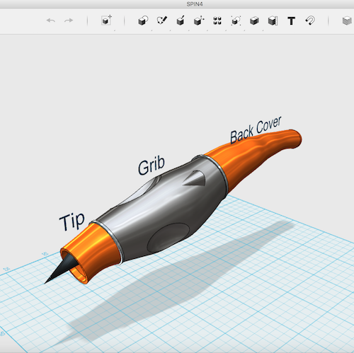
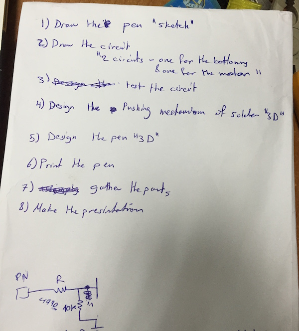
- I decided to start with sketching the SPIN "Soldering Pen"
- Next step is to design the circuit and testing it after programming
- After that I have to design the solder pushing mechanism and testing it
- Designing the grip and implementing the pushing part to it
- Printing the part using the 3Dprinter and finishing the assembly of them
- Finally is to revise the documentation and make the presentation Video and photo
- Enjoying a good night sleep after that :D
Introduction
The main purpose of the electronics is to control the motor responsible for solder feeding, I wanted to add heat controlling feature to this prototype version but I decided to add it to the next one due to the shortage of time frame
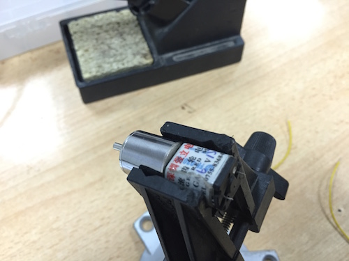
- I wanted to test my geared motor before connecting it to the board
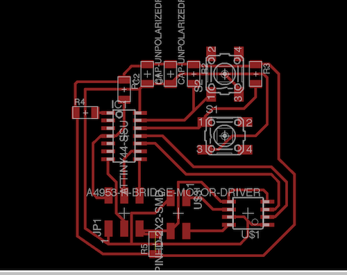
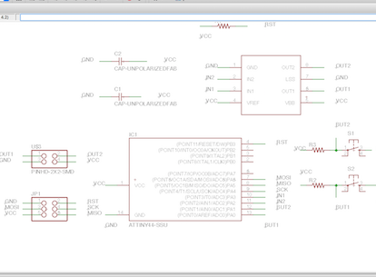
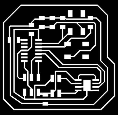
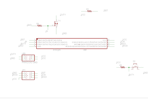
- I started designing my board that contain a motor driver "H-bridge" in order to control the forward and backward movement, it was similar to the design in the Output Assignment except that I added to push buttons one for each direction
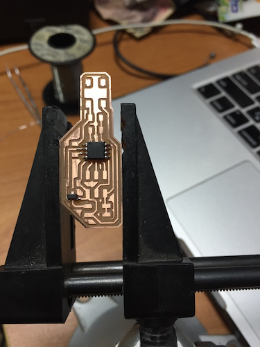
- After I soldered the components and connected the motor, I wrote the code using arduino
- The main problem that I faced when I tried to test the motor is that I mistakenly didn't connect the driver into the Analog "PWM" pin of the ATtiny, instead I connected them into Digital pins, which prevented me from controlling the speed of the motor, so I had to re-do everything again
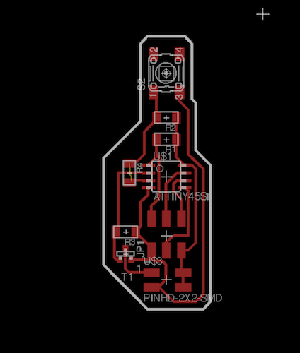
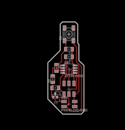
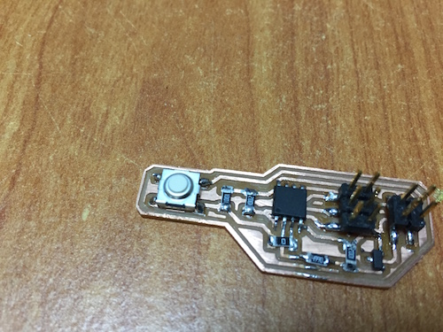
- As I want to attach this board to the pen it self near to the grip, I decided to make it smaller
- In order to do that I excluded the backward movement feature of the board so i could use the smalled ATtiny 45 and only one push button
- I used the Mosfet transistor to control the DC Motor
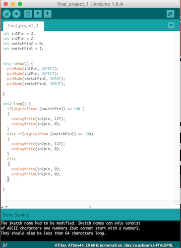
- Now after I connect the Mosfet into the ATtiny Analog pins I can control the speed of the rotation
- As you can see if you want to determine the speed of the rotation you have to write it in no. range form 0 to 255, I decided to use half speed so I wrote 130
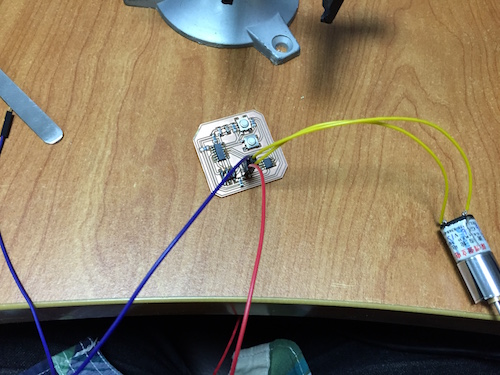
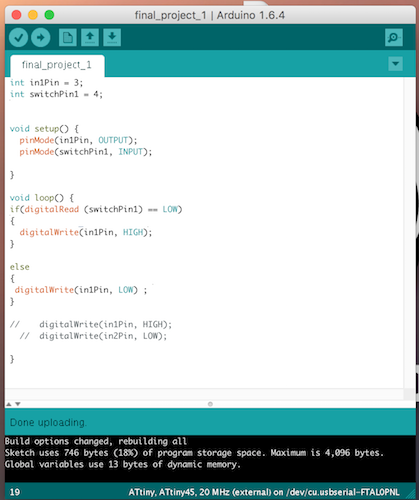
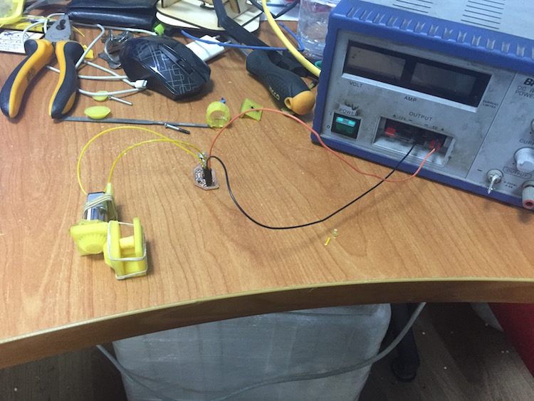
- I faced a problem after connecting the motor to the board, as it won't work when I push the button
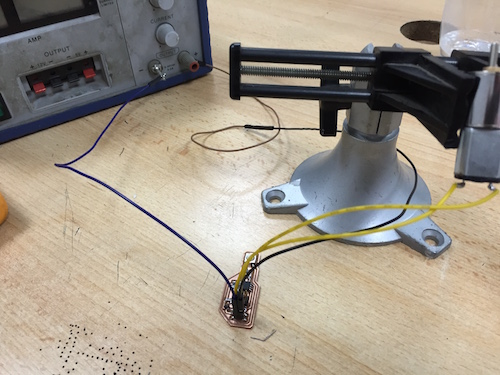
- After rechecking the schematic and the soldering connection, i thought of testing the circuit with a LED
- As you can see the circuit is working fine with the LED but won't work with the DC motor
- After a long period of debugging the circuit I get disappointed as I can't find any thing, I even thought of running the motor without the Micro controller, but then I will lose the feature of controlling the speed of the motor
- Finally and thanks to my friend Mohamad Kamel who helped me in fixing the problem, and after a deep search in Mosfet data sheet we found that we have to redesign the board to add a resistor between the microcontrollar controlling pin and Mosfet, and that what we did :D
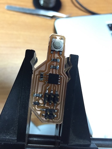
- Finally it is on and running, now I am ready for SPIN "My project name :D" Designing phase
Download Board
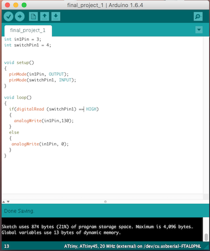
int in1Pin = 3;
int switchPin1 = 4;


void setup()
{
  pinMode(in1Pin, OUTPUT);
  pinMode(switchPin1, INPUT);
}

void loop()
{
  if(digitalRead (switchPin1) == LOW)
  {
    analogWrite(in1Pin,130);
  }
  else
  {
   analogWrite(in1Pin, 0);
  }
}
Download File
Introduction
In this phase I have to design both a case for the Soldering Iron and a case for the motor and pushing gears
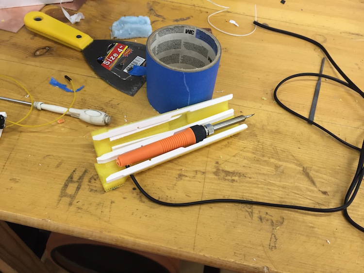
- Originally I wanted to make the soldering Iron my self, but I decided to buy a working soldering Iron and case it so I can hold it like a pen as a primary step to test the project first
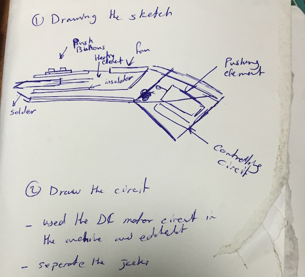
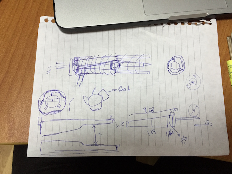
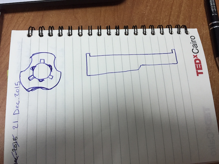
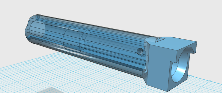
- First I took the measurements of the soldering Iron and I sketched the case on paper, I make it cylindrical cover that hold the iron in the middle by 3 inside extension so there will be a space between the Iron and the case for cooling and Isolation
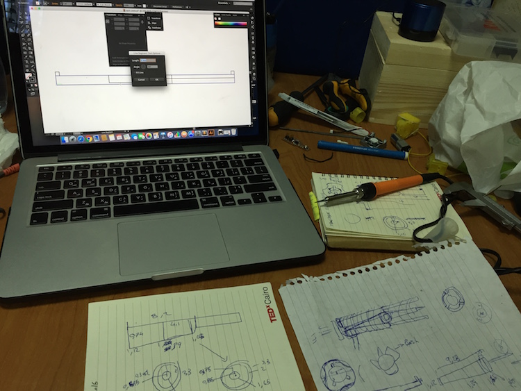
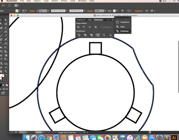
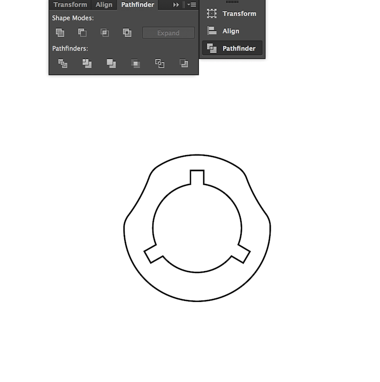
- I started by drawing the sketch with Illustrator
- As you can see I made the shape of a cut section in the cylindrical case and the a 3 connectors that can hold the rings together and fix the Iron in the middle, you can download the .dxf file and make the case with 3 mm plywood 50cmx30cm sheet
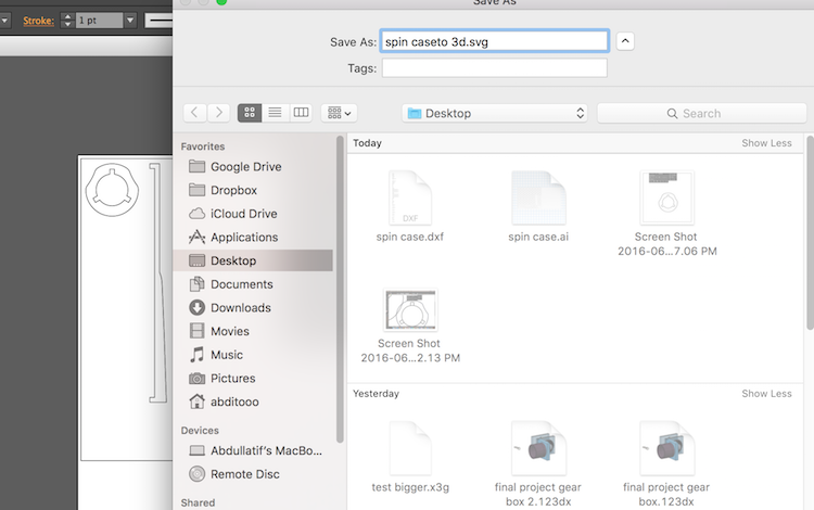
- I also saved the file in .svg to transfer it to 123D Design and make the 3D model
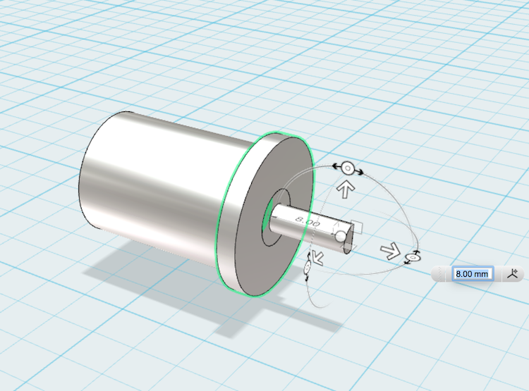
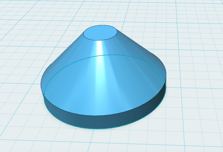
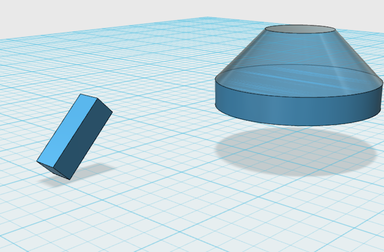
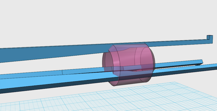
- In the 3D drawing phase I have to design 2 things, the case and the pushing mechanism
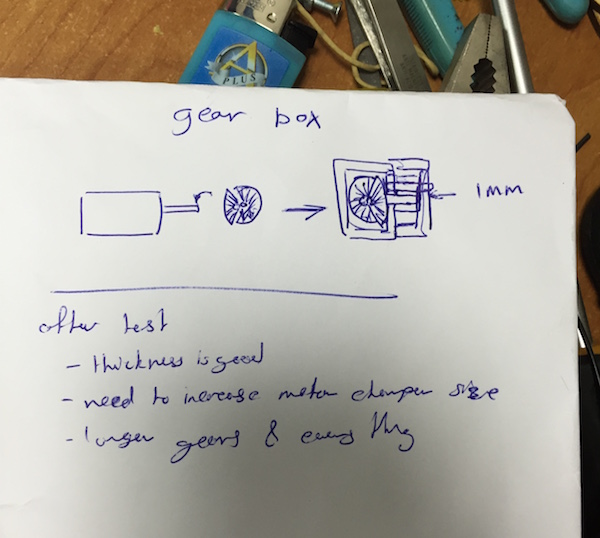
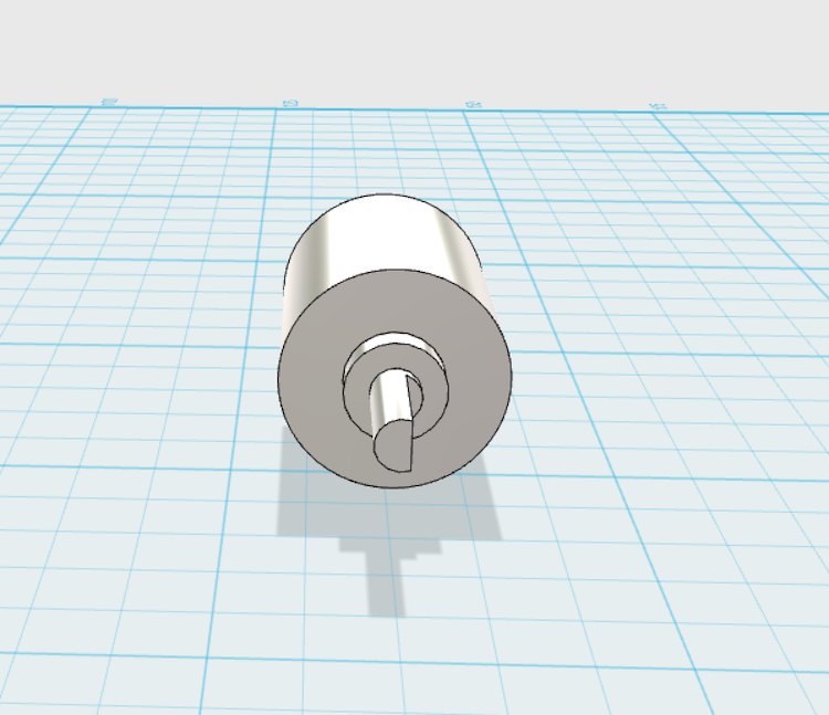
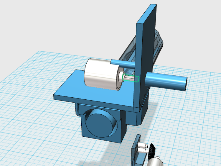
- I started by making the pushing mechanism, and to do that I had to design my motor to avoid measurement mistakes
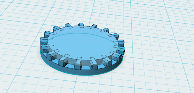
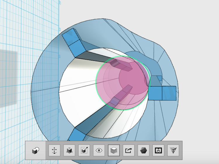
- To transfer the movement to be forward and backward I had to use Miter gears
- I search the Internet for open source design that i can use and I find This one , now all I had to do is to finish the design
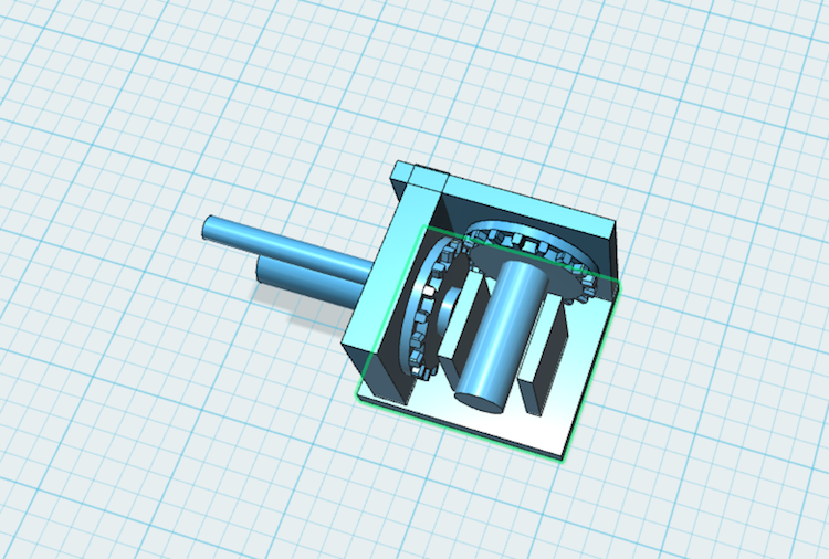
- Here it is
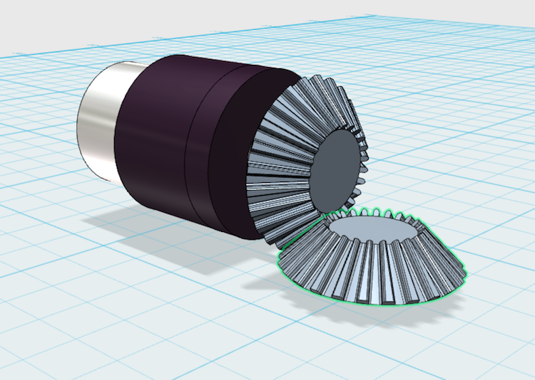
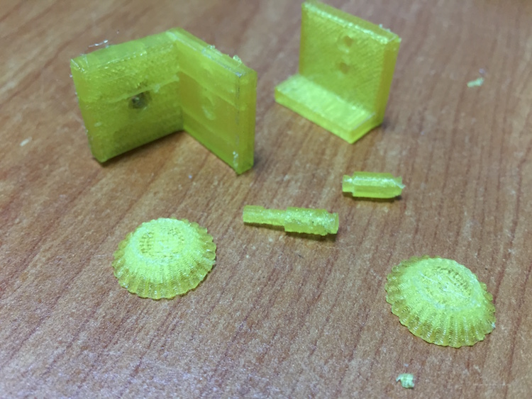
- I printed the parts to test them, and it appears that I have some measurements that need to be changed to fit
- I tested it for spinning and it works, time to test it for transforming the movement
- When installing the second gear I found that it doesn't transmit the movement correctly because the gear tooths are to small and fit correctly with the second one, so I had to do every thing again from the start
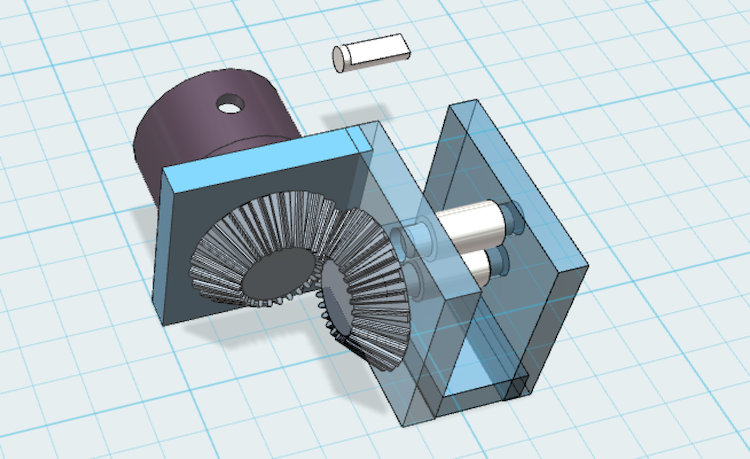
- I decided to change the shape of the gear and to draw it by my self to fix the problem<
- I find this article that helped me a lot about LEGO Gears used in the bricks, so I decided to make the design like it
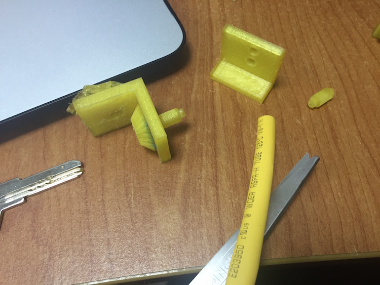
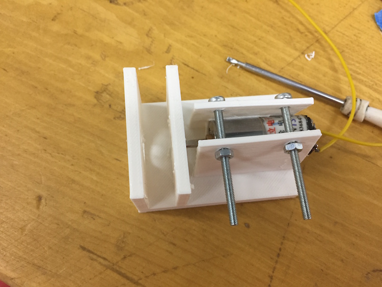
- After all this work I decided to get around the gears Idea and just change the orientation of the motor :D
- Here it is after printing
- Now I have to start designing the case
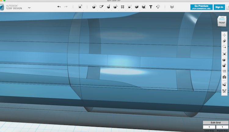
- I started as I said be exporting my .svg designed cut sections from illustrator and importing them to 123D Design
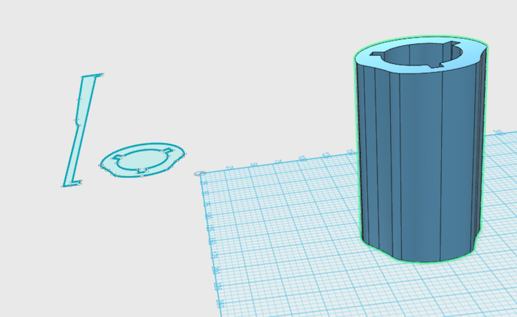
- I extruded them after that to covert them from 2D into 3D
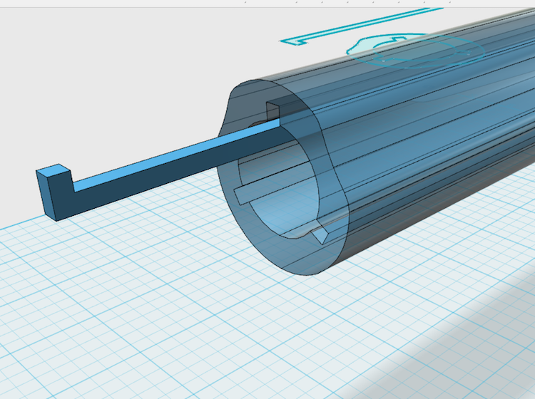
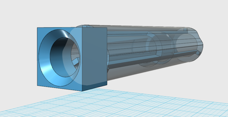
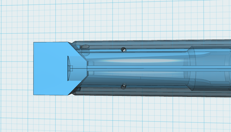
- I made this part to be open from the inside to allow the ventilation of the tube
- I was intending to use this fan for ventilation by making it suck the air and push it outside the tube, so I had to add a dock for it at the end of the pen
- Here is the fan dock
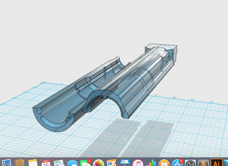
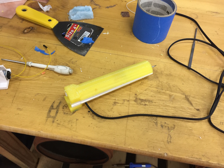
- Finally and before printing it I sliced it in the middle to reduce the need for support as much as i can
Download File
Download File
Download File

Download File
Introduction
I will list here the assembly process and the outcome after testing, also I will include the materials and components required, and their costs by EGP
- I will include the materials, components and their cost first, I bought most of them from "Ram, ElNekheli or Al Amir" in Down Tower, some components and services like 3D printing I get it for free from Fab Lab Egypt
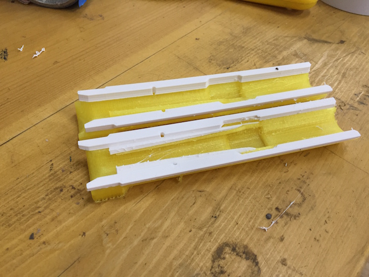
- While i was printing the case, there was a power off (bad luck hits again :D) and the printer stopped in the middle of the case, so i had to slice the design at the point that it stopped (I measured it by ruler) using Meshmixer and glued the parts using polyfast :D
- Thank to God the Measurement was perfect, so I cut the wire and pass it through the hole so i can close the other side perfectly
- The only thing that i didn't calculate correctly was the measurement of the ventilations, as the Iron body closed all the space and the Ceramic Insulation around the heating material filled all the space, so I didn't install the fan as it won't be of a benefit
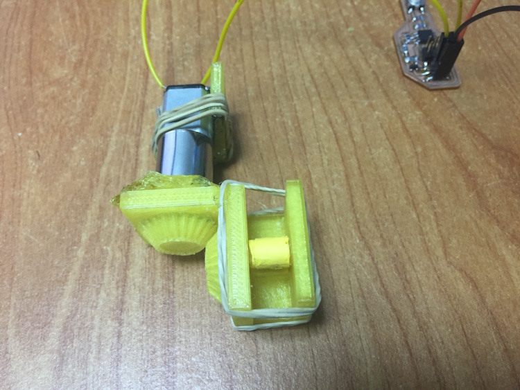
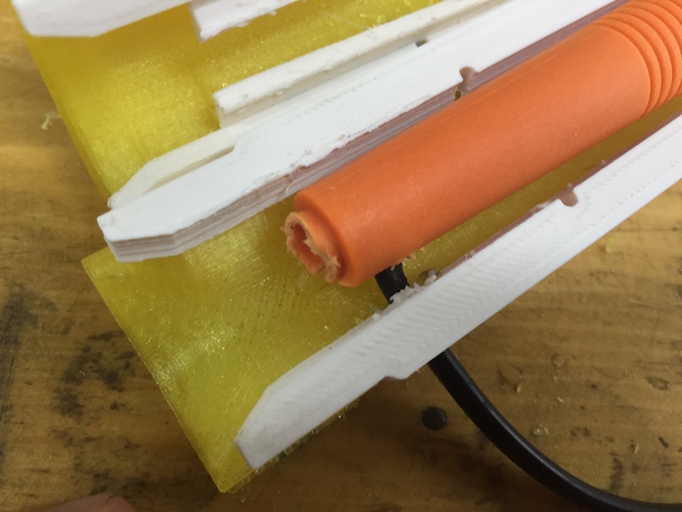
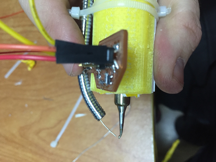
- Preparing the pushing element, I used heat shrink around the two rods to increase the friction while pushing the solder
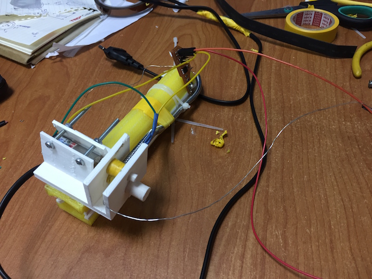
- Gathering all the parts and fixing the pushing components on the case
- this is a time laps for all the assembly process if you want to check it, it is a little bit messy where I work :D
- Finally here it is :D
- I included almost all of the references that I used within the documentation it self, and I had to thank all the Mac OS users in the past Fabacademy years cause they helped me a lot with their documentations in solving some of the problems that I faced
- Big thanks for all the people that helped me, especially the guys here at our makerspace "Fab Lab Egypt"
- I used most of what I learned via the weekly assignment in my final project, and I will try to use the rest in next prototype
-
I decided to Copyright the project under a "Creative Commons Attribution-NonCommercial-NoDerivatives 4.0 International License"

- My future plans is to make a Startup that will manufacture and sell this project as a product to help all the Makercommunity newcomers and amateurs, also to make the soldering process easier and safer than ever for all the ages that can use it
- My next step is to work on the 2nd version of this prototype to make it more ergonomic and to fix the stuttering in the pushing mechanism, and also to fix the ventilation system although I turn it on for 36 min. without feeling high heat at the tip where I am holding the Soldering pin
- I called it "SPIN" which is a short name for "Soldering Pen" with a twist of replacing E with I in Pen, but I think I will change it to a much cooler name :D, If you have any suggestions don't hesitate to tell me :)
| Materials | Cost | Electronic Components | Cost |
|---|---|---|---|
| Board for the circuit | 3 EGP | Jumpers | 5 EGP |
| Heat shrink | 5 EGP | Geared DC motor | 90 EGP |
| PLA Plastic (90 gm) | "free" | Resistors, Mosfet, Attiny 45, Push Buttons |
"free" |
| Soldering Iron | 35 EGP | ||
| Utilities (nuts, polyfast...etc) | 20 EGP | ||
| Ceramic Insulation | 20 EGP |

Final Notes:
Final Project Poster and Video: