Week 8: Embedded programing

This week is dedicated to program the Helloboard done during the Week 6.


my chair!

Some explanations


SPI communication

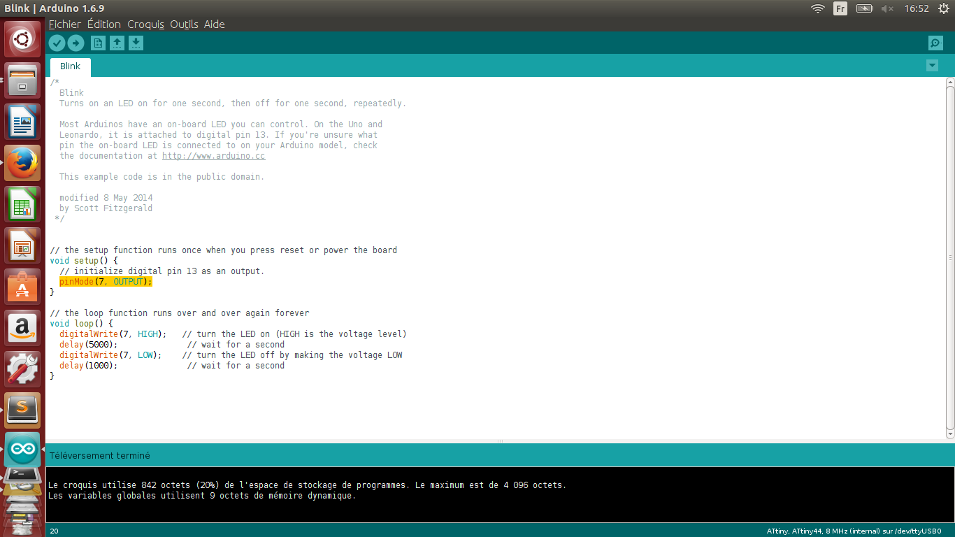
The Serial Peripheral Interface (SPI) is a synchronous serial communication interface specification.

It works in a Master/Slave configuration in order to exchange bits between systems.


schematic of a master and slave config

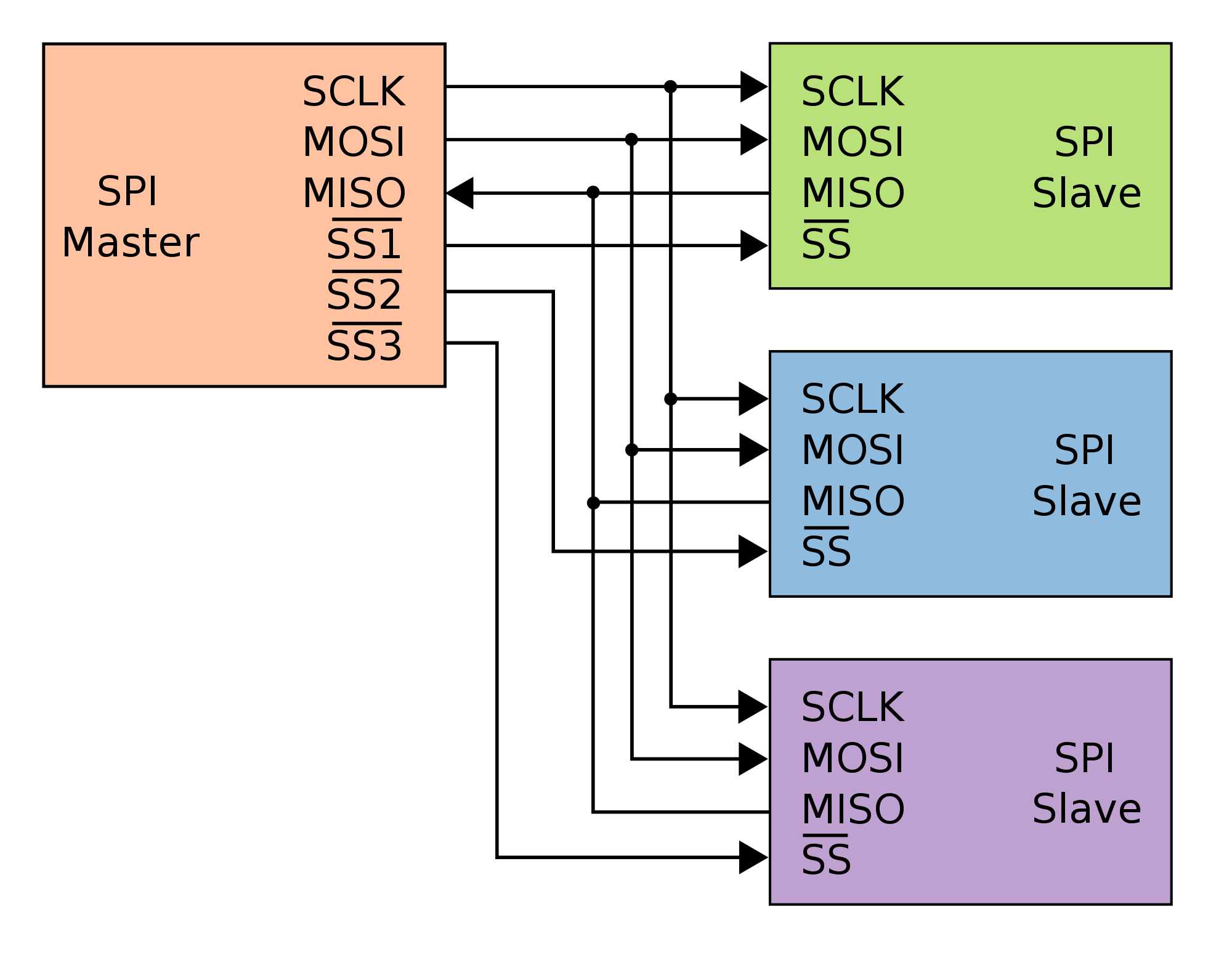
SCLK: is the pin coresponding to the shared clock, since the communication is synchronised, we need to have a common time referential.

MOSI: stands for Master Out Slave In, basicaly it is the transmit pin.

MISO: stands for Master In Slave Out , the recieve pin.

SS1,SS2..: this specifies who the master is talking to, generaly by beeing pulled down .
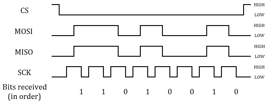
SPI on an oscilloscope

This is what a serial communication looks like on an oscilloscope.

Avrdude

avrdude help menu

The major features of AVRDUDE include:

  • Command-line driven user interface for downloading and uploading features.
  • Interactive examination and modification of various memory regions.
  • Supports a wide range of programming hardware such as cheap ISP plugs.
  • In "terminal mode", the device's memory areas can be examined, and possibly modified. This allows to set fuses interactively, or to modify a few EEPROM cells.
  • Documentation can be found: here

    Reading the date sheet
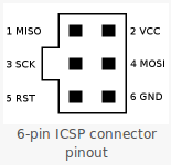
  • Is the part over voltage tolerant?
  • How much output current can this part supply?
  • How many pins can I use do to some serial communication?

  • Connections

    Because I always forget them, this might be usefull:

    SPI connections

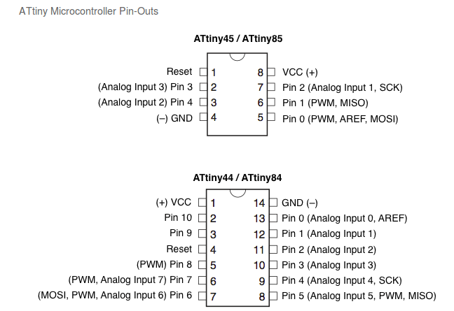
    And also the pins for the Attiny:

    attiny pins

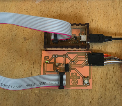
    Programming the HelloBoard

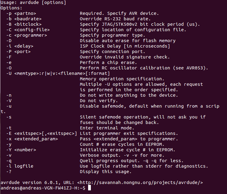
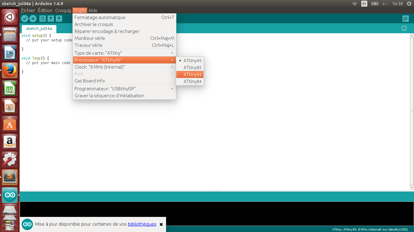
    I decided to use the Arduino IDE to program my board

  • I started by downloading the last version of Arduino
  • Plugged my HelloBoard to the FabISP using the ISP cable and to the computer using the FTDI cable (one led lights up when the board is powered):
  • Succes!
  • Then I downloaded the Attiny library for Arduino so I could directly upload sketch to an ATtiny,I specified the board type:
  • Attiny and arduino!

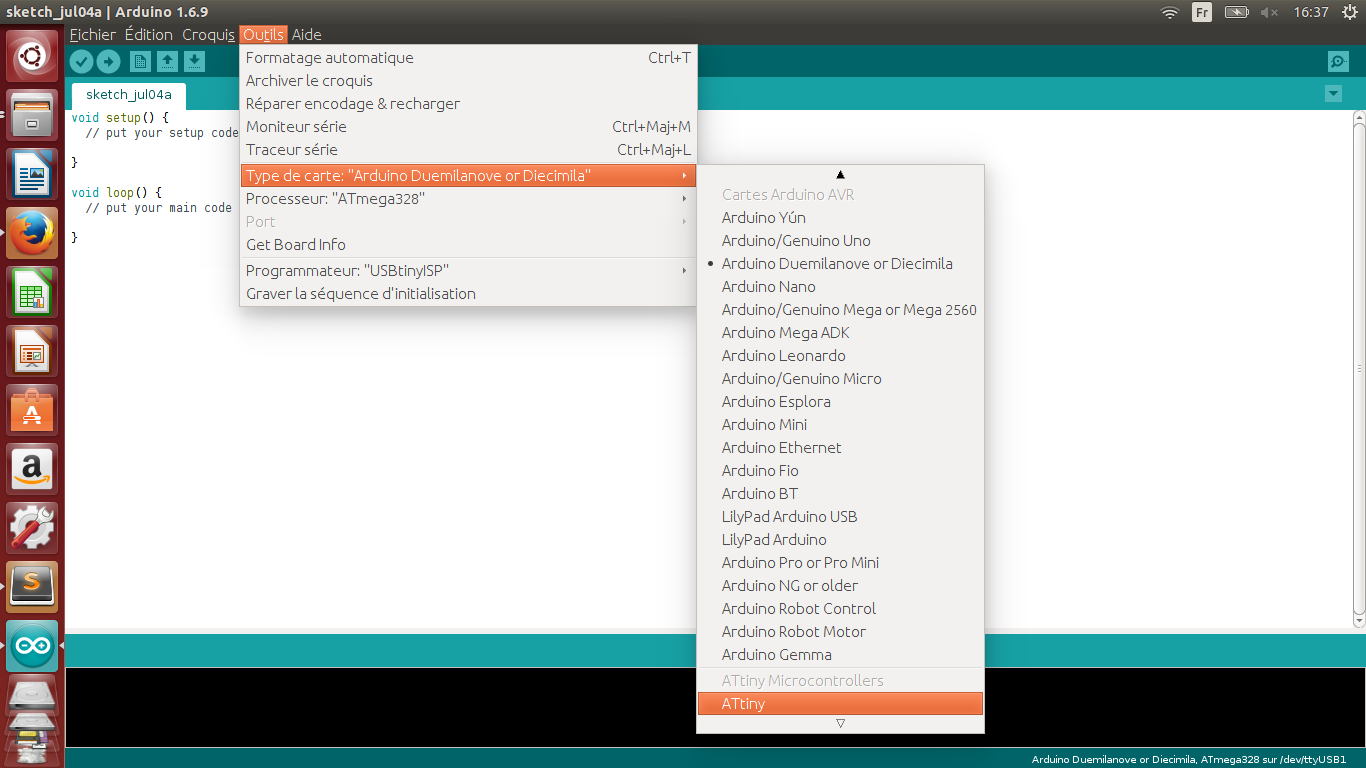
    And precisely the ATtiny44:

    Attiny and arduino!

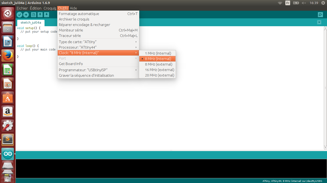
    I needed to tell to the IDE what clock am I using, this will modifie the bootloader accordingly (All the ATtiny chips have an 8Mhz internal clock) .

    Attiny and arduino!

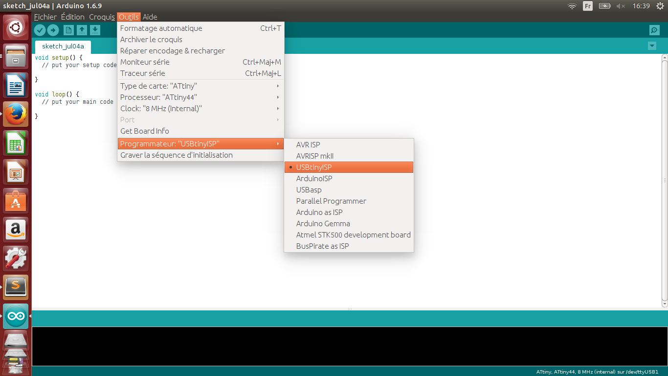
    And also specifie what kind of programmer I was using (the USBtinyISP) :

    Attiny and arduino!

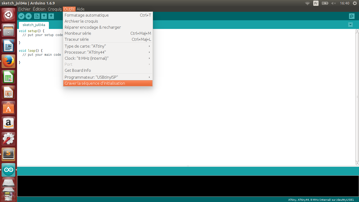
    From there everything was ready to burn the bootloader!

    Attiny and arduino!

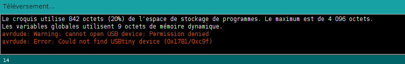
    This is a common mistake (on Ubuntu OS), some times there are permissions issues with the serial ports, but no worries, I did found how to change that:

    Attiny and arduino!

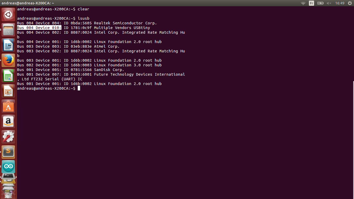
    Typing "lsusb" shows all the USB interfaces, you obtain the port and the number of the device: "Bus 004 Device 010 ID..."

    Attiny and arduino!

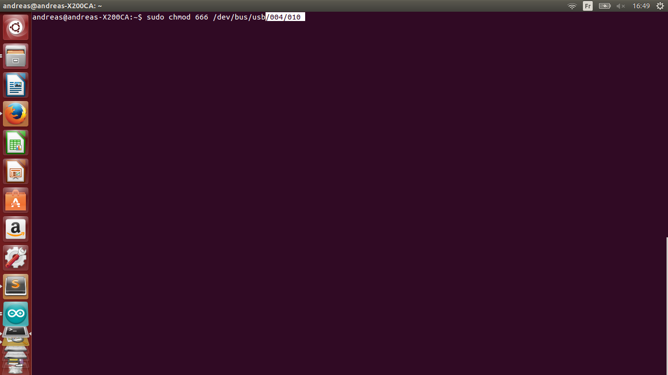
    To change the permissions setting: " sudo chmod 666 /dev/bus/udb/004/010" (replace my values by yours)

    Attiny and arduino!

    Once the problem was solved I simply uploaded a Blink sketch to my board to test it ( after changing the pin 13 to pin 7!)

    Attiny and arduino!

    And then I modified a little bit to code so I could use my button (which is on pin 6 in my case):

    And build a little laser cut casing with a 3D printed button:


    I loved this assignment, compared to the Week 4 (FabISP) where I did things without really getting it, ths time things became clearer, I think that using both the Arduino IDE and a terminal gives a good understanding of the process.


    Learn Make Share