Week 07 - Computer-controlled Machine
Assignment:
- Make something big!
- Use one OSB sheet - 15mm thick,1220 x 2500 mm
- Learn how to work the Big milling Machine -The ShopBot
- This week’s home work page
Drawing the file:-Rhino & SolidWorks
For this assignment, what took me longer was to decide what to produce. Since the possibilities are endless, picking one above all was not easy task for me.
I've been using SolidWorks a lot since beginning of Fab-Academy for its parametric features, and for that reason I felt like combining it with Rhino, since for me using Rhino still feels like "going down hill".
In SolidWorks, you can import DXF files saved in Rhino by simply opening it. It will automatically show you a DXF/DWG window, I selected "Import to a new part as a 2D sketch".
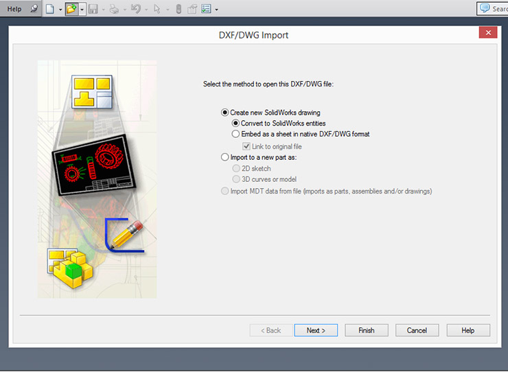
The files can be read by SolidWorks. Just remind yourself to, in the next step, to choose the units you are currently designing in. I use Milimiters, always.
Your imported lines wont have any parameter nor relations, you will have do it one by one. This is like playing chess. Your first moves will determin the outcome of your part. Try not to complicate it.
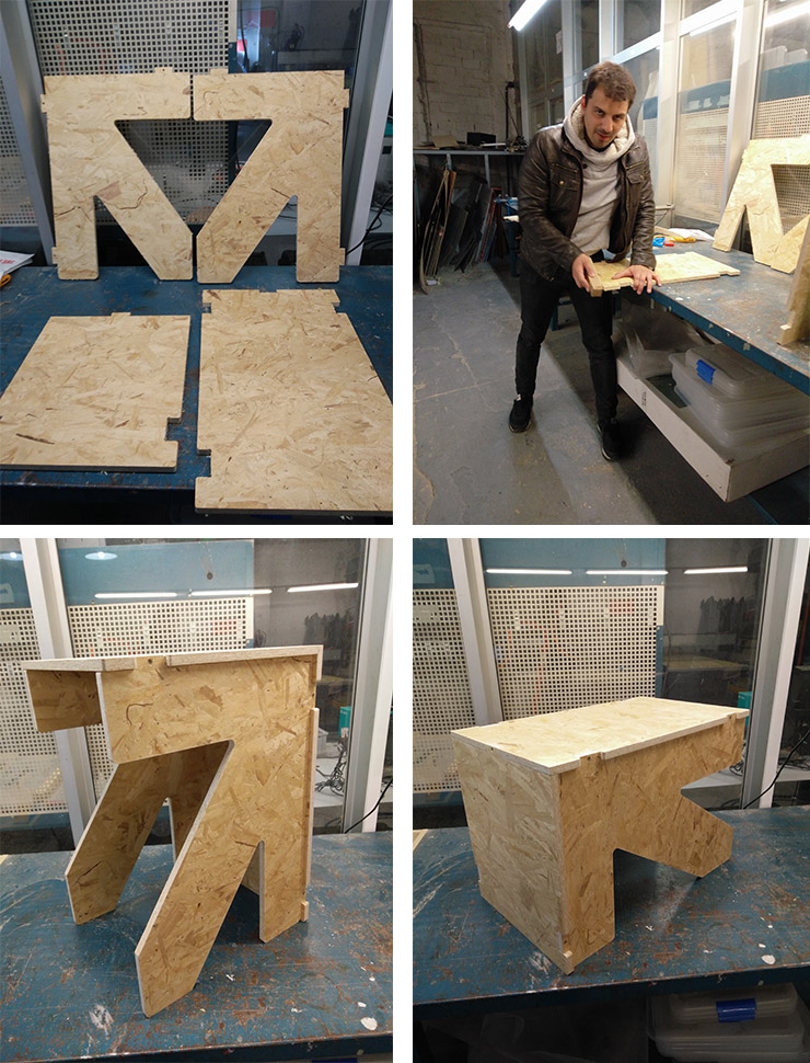
I ended up developing an idea I had years ago and never had the means to make it. I thought of a bench/stool that just by inverting its side, you have a coffee table. The design is simple and assembling it was simple.
PartWorks V2.5 Milling Software: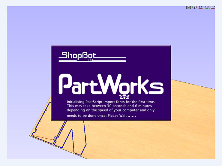
The next step, once the file is ready, saved and exported, is to open it in the CNC software.
for that we used PartWorks, Shopbots' software, since FabLabBcn owns one.
This software is pretty straight-forward.
Start by job setup, where you place the size (width x and height y), Material Thickness, Z zero (Bottom/Top),
XY origin position (one of the 4 corners or the center), Units (MM / Inches) Click ok.
A white area will appear, representing the sheet you'll be cutting.
Import drawing. I used a DXF file. "Import drawing vector", then your file should appear on screen.
If not, try and zoom out. Then Hold "CTRL + A", this should select all lines of your drawing.
Then under "Align Objects", hit Center Button. If you did everything correctly, all should be centered now.
Now to join all your lines (You must do it), again "CTRL + A" to select all, and under "Edit Vectors" hit Join Vectors.
If you still shows opened objects, go to the Menu Edit -> Select All Open Vectors.
It's advisable to check for duplicated Vectors, on: Menu Edit -> Select All Duplicate Vectors.
Let's start our toolpath:
"CTRL + A", -> Toolpath tab (on the top right of your screen)
I used Profile toolpath option (2D Profile Toolpath will open)
The first set of values (top) are to control how deep the cut will be.
If you have a sacrificing sheet on your milling machine, the "Cut Depth(C)"
should be a bit bigger than your sheet thickness, lets say you cut a 15mm mdf,
then make it 15,2mm so you know it cuts through.
"Start Depth" is in case you dont want to cut the whole 15.2mm in one go, but
let's say you want to do it gradually. Place the step you want to take here, for instance
6mm so you'd cut it in 3 steps.(6mm + 6mm then the machine calculates the difference,
cutting the last step 3.2mm (Instead of 6mm). 6mm + 6mm + 3.2mm = 15.2mm
Milling Bit
Now coming next is the option to set your milling bits. Select yours of add one and custom it.
Depending on your project, you know decide if you want it to cut from inside or outside.
In my case, I needed it Outside cut, cause my drawing was done so.
A VERY advisable tool is the TAB option. Use it if you dont have a vaccumm table, and sometimes even if you have one.
The TAB is a little bridge between the parts that are left uncutted, normally in the last step of the toolpath.
If you do not place them, you will have a big mess and probably chances are that your milling bit can break.
Name you file, Calculate it and use the previews. You have even one in 3D.
Save it and your file is done, or almost done. I added another toolpath, the Drill Toolpath, since I used screws to fix the OSB to the table, so I added some circles in my drawing. I used a 6mm diameter S2 Flat-headed milling tool, and for the fixing I used a 4mm normal drilling bit.
My part also had another drilling on its own, so I made another Drilling toolpath, this time with the 6mm bit.
If that was not clear enough, I suggest this tutorial.
Once your file is ready, it is time to CNC it.
CNC milling: Here we are with our BIG milling machine. We are particularly using a ShopBot, which is the machine we have here in FabLabBcn.
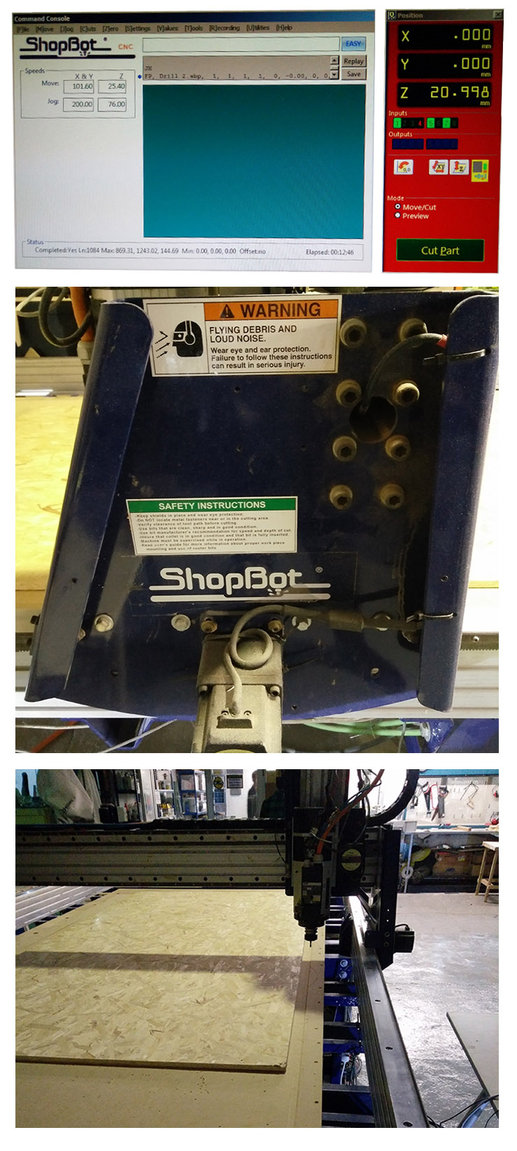
Similar to the the Roland cnc milling ones, we must place our material (fix it), set X and Y, and Z. Z we must set every time we change tools/milling bits.
Once this is done, we run our first file - holes to fix the OSB board to the machine's table.
Now that we have the board fixed against the machine, we can start our second job that, in my case, has Drilling and Profile toolpath - in this order.
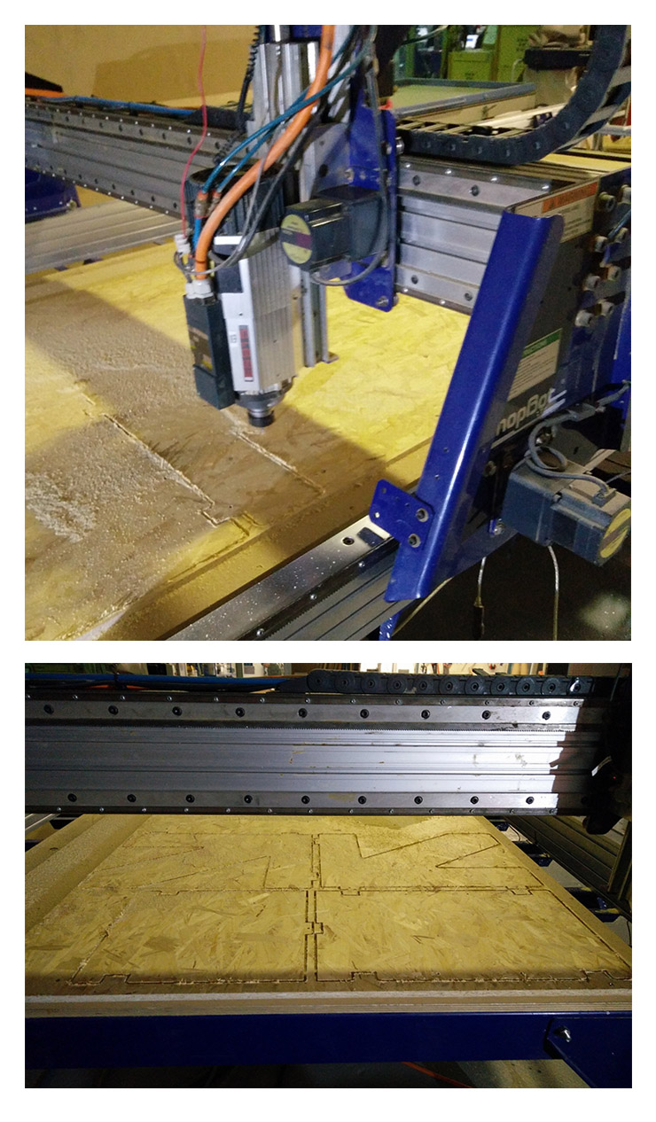
After the job is completed, time for cleaning (Vaccum cleaning) and removing the parts and the screws to release the sheet.
The fitting was at my pleasing but still needed some sandpapering for smoothing and also due to the tabs.
Files:Drill toolpath ShopBot for screw fix
Drill and Profile toolpath ShopBot
PartWork file (.crv)