Week 03 - Computer Controlled Cutting
Assignment:
- Design, make, and document press-fit constructions
- Use parametric design tools
- Learn how to use the laser cutter and the vinyl cutter
- Use Cardboard
- This week’s home work page
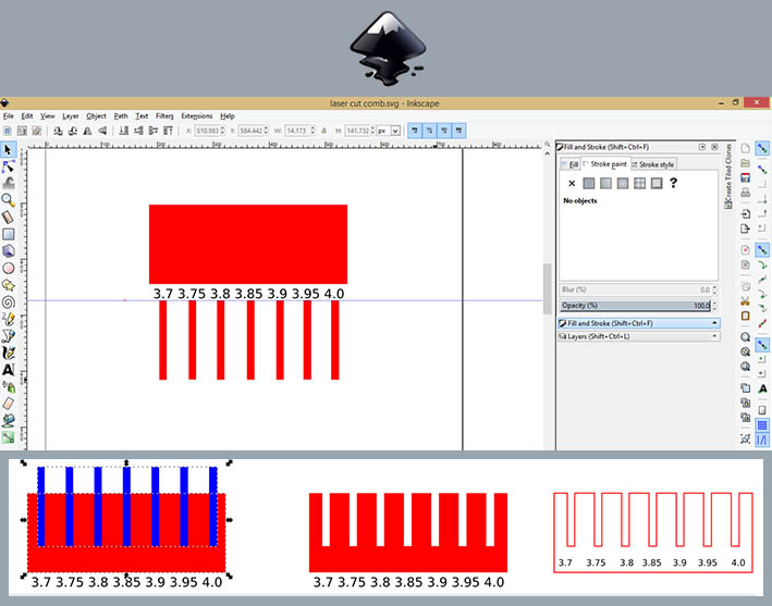
Laser Cutting:-First I started with Inkscape to create a comb with different gap sizes, ranging around our material's thickness. This was done in order to find out the exact kerf size that our laser cutters will produce, for this specific material (Cardboard 3mm).
I must admit this was very useful. And simple. Didn't take more than some minutes.
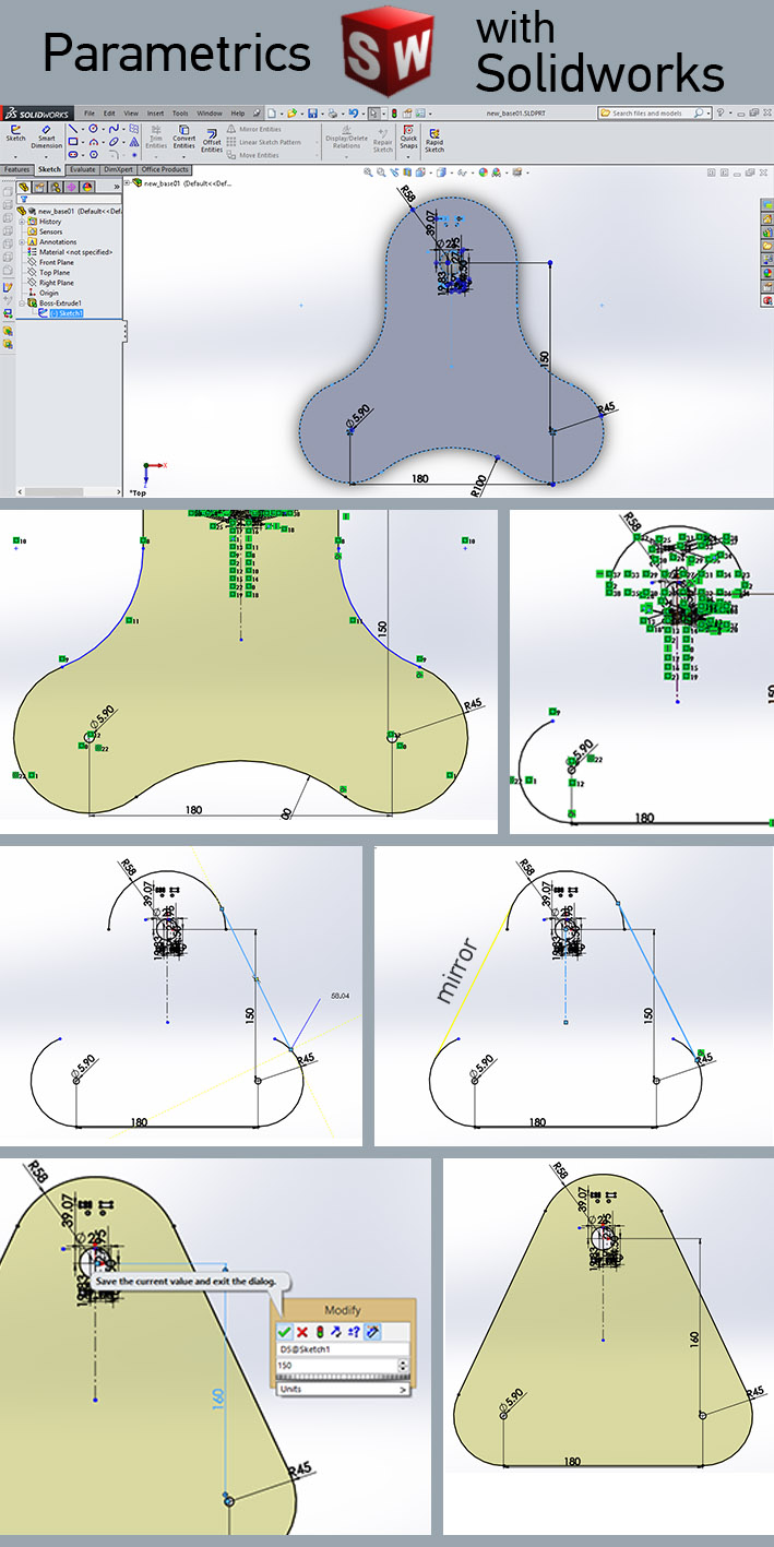
-Now to design my files in a parametric software, I moved from Inkscape to Solidworks.
Because I'm developing a robotic arm to be mostly lasercutted, I must count with, to begin with, difference of material thickness.
I don't want that everytime our team decides to use a new material or thickness, that we'll have to redesign all the parts.
First things first, I started from the base of the arm. I set all my "Mates" and dimensions that corelate the lines and arcs.
Once this is done, whatever I want to do on the part or the assemble, the software understands my changes and update it, as the example below.
I try to design one part and to mirror it or to create patterns, this helps the software to create the relations within the designed part.
From the first step in Inkscape, I got the kerf of the 2.8mm cardboard, lasercutted on the trotec laser of our lab. Important to mention different lasercutters will give different Kerfs.
Now knowing the Kerf, I updated all my dimensions and tomorrow I'll cut the first parts.
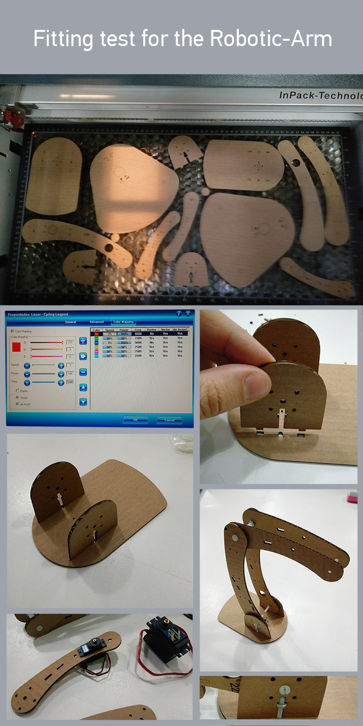
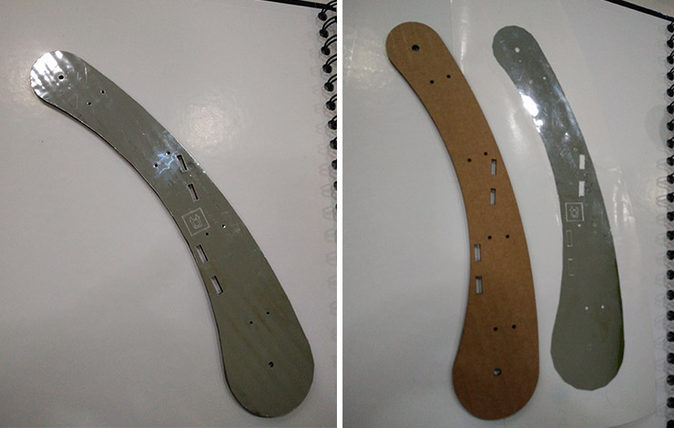
-Since I had to use cardboard for this week's task, I proof tested all my parts to check if they were fitting and alined. Cardboard is a good material for that since it is cheap, cuts fast and recyclable. Lucky me, the servos and the nylon bolts arrived just in time to cross check their precise size. For that I used a caliper to measure them. Since I brought and setted up my files in Solidworks, adjusting the dimensions was an easier task. If you check out the process above, you can see some dimension editing.
Gladly, the micro servo worked out fine, as well as the nylon M4 screws. The high-torque servos need a 3D printable little structure that I'll develop during 3D scanning and printing week.
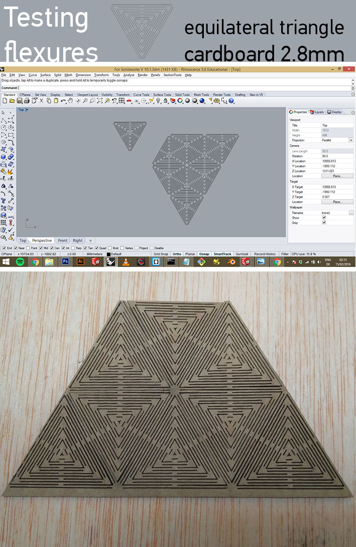
-Flexures were something that amazed me since I first saw it. Isn't is incredible do make a hard material flexible? I still see a lot of potential to flexures.
I was at Vall Daura with our whole group when Caro Vignoli asked me about multi-directional flexures. I couldn't resist but to start playing with some patterns we discussed. Next step now is to redesign this in Solidworks in order to change parameters.
This was our first result:
Vinyl Cutter:
As part of our task, we also had to learn how to use the Vinyl Cutter.
Felt like integrating tasks so I created a sticked for the robotic arm.
I like the idea of covering materials to make them look better. That probably comes from the background as
furniture designer and the vast exposure to carpentries. There, it is common to laminate Plywood with veneer - thin sheets of real wood, glued with contact glue normally -
The machine was a Roland GX-24 CAMM-1 Servo
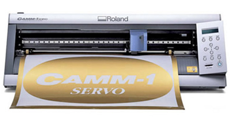
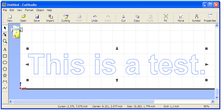
There's a software from Roland called CutStudio where you can prepare your file and communicate with the machine (Send the job).
For my Sticker, I found a nice chromed material. It is a bit harder than normal material, but also cutted with the same settings.
-Download my files:
-Solidwork's Base of Robotic-Arm_ Parametric
-Flexure - Equilateral Triangle_dxf file
-Vinyl vector files - SVG & DXF
Back to top