Home
Biography
Projects
Final Project
Machine Design and Construction
This was a group effort, and the primary documentation can be found here
This week was a group effort, and my role, alongside Kadin, was to assemble and debug the electronic components of the machine. Since it is important for all members of a team (design, programming and assembly) to undersatnd the stucture of the machine, we first decided to assemble some of the MTM cardboard stages.
Stage Construction
The design for the cardboard stages are from MTM, and Steven used RhinoCAD (I found a copy lying in a drawer in the FabLab) to resize the parametric file to our material, which was polystyrene board. We used polystyrene board instead of the cardboard, because it was cheaper, easy to bend, and the fact that we wern't planning on using them for the final product, since neither cardboard or polystyrene board would be structurally sound enough. This exact design wasn't used, but a similar design was used for the machine itself.
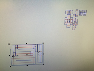
We used CorelDraw to send the vectors to the 60 watt lasercutter, since it used a similar cut process as AI, but we would be cutting 4 out and we wouldn't need to convert or resize any artboards or change file formats. Just as in AI, we opened the settings for the cutter, set the speed to 50% and the power to 40% for the blue cut lines and a lower value for the red scoring lines. We then sent the vectors to the lasercutter. Two sheets will be necessary, one for the body and the other for most of the carriage.
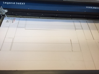
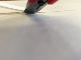
The cut lines will break away from the scrap material easily, while the score lines will allow you to snap the polystyrene board into shape. There are sets of single lines and double lines. The single lines will fold away from the cut, while the double lines fold towards the cut. To enable the double lines to do their job, make a V cut, removing the top paper layer of the board.This cut will make folding it so much easier.
After cutting the
fold lines, you can now assemble the stage shell. Below is a GIF (from the MTM page) of what I will try to explain, so if you watch that very closely, you can skip my (probably poor) explanation of the stage construction.
My direction will probably diverge from those that you see in the GIF, since we used a different material and didn't plan on using the stages.
Steps
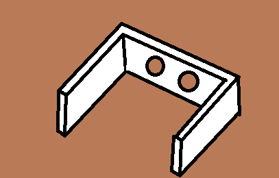
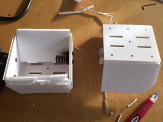
- fold these two pieces together as seen in the image and place them on the large center piece. These will be covered by the outer parts of the stage. The rectangle piece in the middle in the image will not be used, but it could be used for something else. On the piece with three large holes, the center hole is closest to the bottom (yes, it isn't oriented correctly in the image)
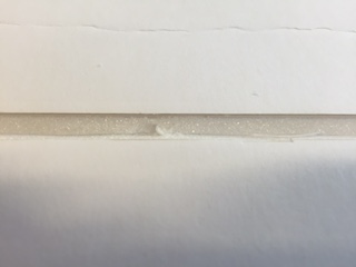
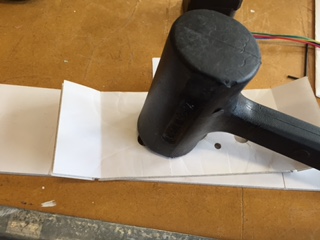
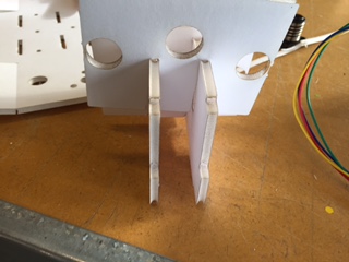
- Before closing the outer shell completely, fold the two smaller scored pieces in a similar fashion. Once again we must deal with the side with the three large holes. It needs to be pounded thinner with a mallet, since the screws that usually come with the gestalt kits are too short to fit through two layers of polystyrene board.
- Now screw the stepper motor into the two foam pieces with three holes in them after attaching the linear drive screw to the motor. insert the folded assembly back onto the main body.Image below shows what this should look like (I know they're not a real photos, but we trashed the stages after we were done with them, so I had nothing to photograph)
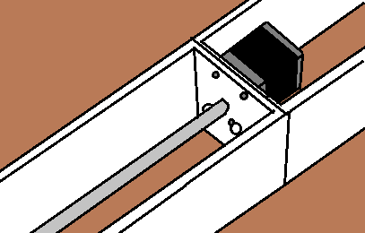
- This part, shown (what it should look like) below in the high definition image, goes into either end of the main body opposite of the pieces we installed/hammered two steps ago. These will also be folded into the main body.
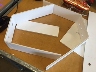
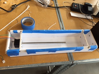
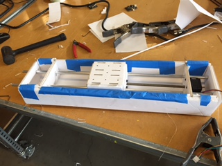
- No we can do what I have been referencing this whole time: folding the main body. With polystyrene board the paper will peel off the core, so it is a good idea to reinforce the folds with tape. When you are finished, the stage will look like this:
- Now we can assemble the carriage, the part that moves across the linear screw. Start by slotting the internal peces together. It helps to champfer the slots here. The sides with a part cut off of it will be on the same side, and once again, be sure to mind that the holes stay on the bottom of the carriage.(Once again the orientation is wrong here)
- Now fold the carriage upper body and lower bodytogether and use the slots and tabs to align them. This is where the cut off parts come in handy, you can easily rotate the piece into the lower body, when combined withthe curve of the upper body. You also need to attach the screw/spring assembly in. You should only need two screws. This will enable the carriage to move along the linear screw when it rotates.
- Now fit the pieces we made in the last step together. Again, remember that the middle hole stays at the bottom. Secure the sides with tape if you wish to.
- Now install the carriage into the main body. Place the carriage in the gap between the linear screw and the wall. Position the screw so that it lines up with the middle hole (that is on the bottom). You will have to manually twist the linear screw to install the carriage.
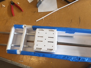
- Insert the nylon bushings into the other four holes on the carriage. Now you will insert the aluminum tubing (robot straws) into the stage, through the four bushings and carriage. The two robot straws along with the nylon bushings will allow for smooth motion of the carriage. Your stage (minus the electronics) is now complete.
Electronics
With the stage out of the way, I could move onto my responsibilities for this lesson: electronics assembly and programming. I started with assembling the wires. The input and output headers of the gestalt nodes are 10 pin headers, so I used the 10 pin sockets we have in the Fab Lab. These sockets crimp down on ribbon cable and pierce the insulation, making contact with the conductor.
Our FabLab has a very outdated inventory, so we
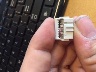
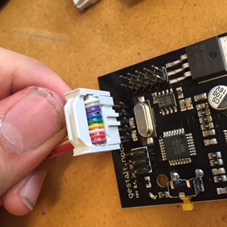
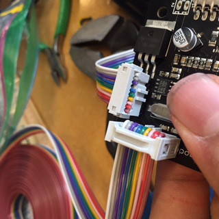
only have 9 wire ribbon cable. Thankfully, the Gestalt node has one pin that is not connected to anything. However, that pin is not in a convenient place to have the ribbon cable moved to one side or another, so we need to split the cable 6 to 3 on both ends. I made sure that the same colors are split off on both ends.
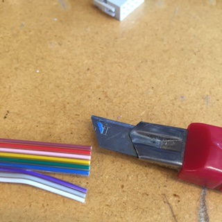
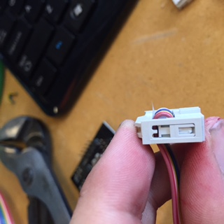
I then inserted the ribbon cable into the socket, making sure to leave the unconnected pin unconnected to any wire. I usually use the brown wire as the ground pin, so I lined that up with the arrow on the keyed end of the socket (that is facing the other direction in the image below). In the image below, note the missing wire that would be connected to the unconnected pin.
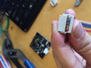
To finish the job, I used a wrench to press the pins down onto the wire, completing the connection. Later, I found that a mallet works much better for this task. This is necessary because when fully wired, it is difficult to compress the connecor by hand. Do this gently, because if the angle is a little off, the connector top will snap off.
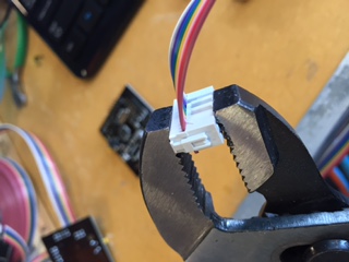
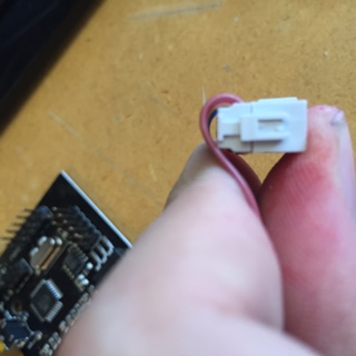
On some connections you may wish to bend the wire over. Because of the number of wires on the 10 pin connector, bending the wire over can cause unnecessary stress on the connector in the future. To fix this, you can attach a
plastic piece over the bent wire onto the connector called a stress releif, it simply snaps on over the existing components of the connector.
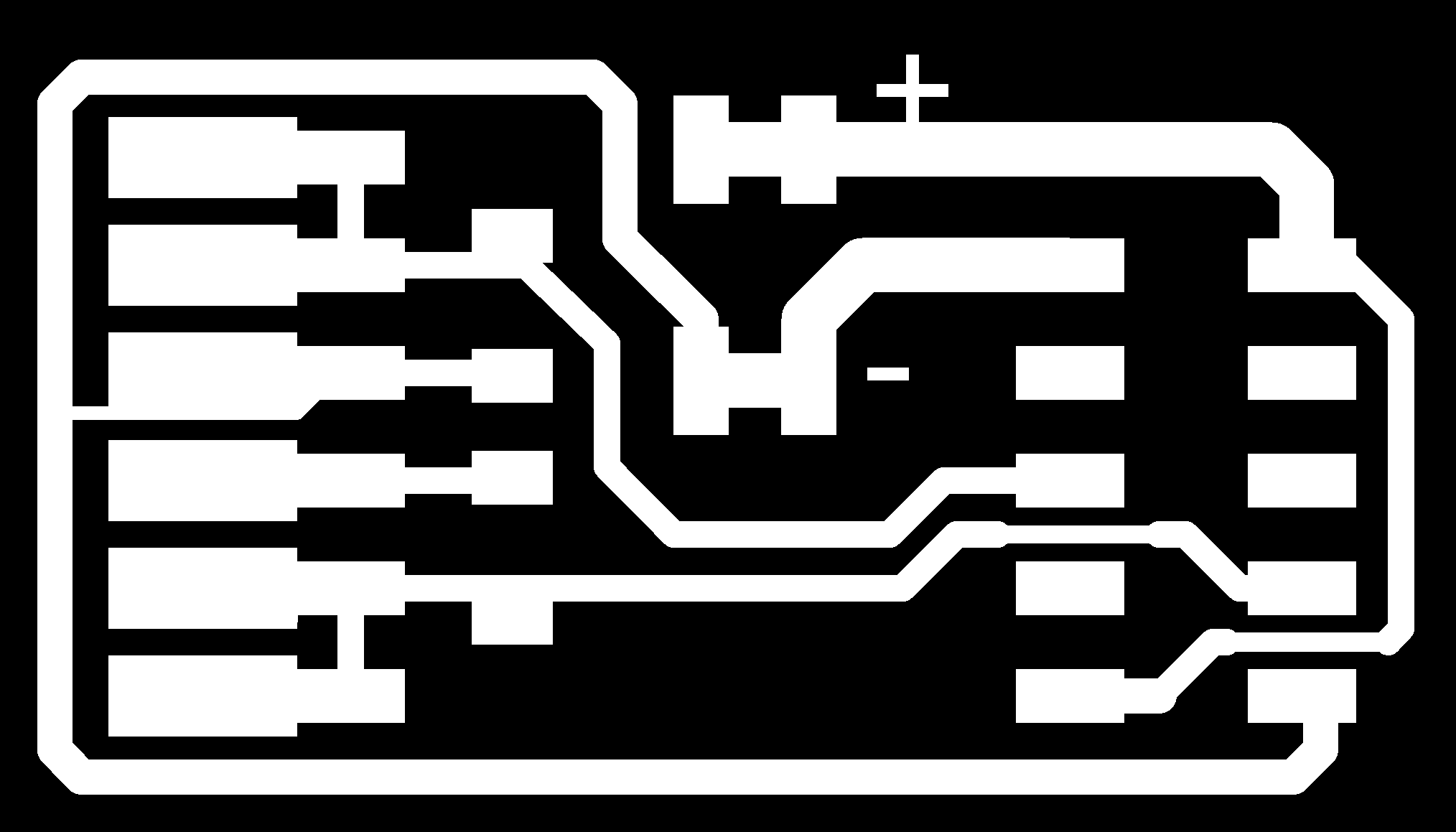
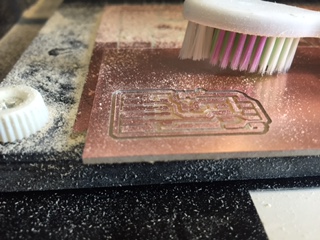
Now that we have made the wires, we can begin to connect the boards. First you need to mill a connector circuit board. This board will attach to a FTDI cable, inject power,
and convert all of that to a 10 pin header. Instead of using the board design that used a nonstandard cable, I used a design that would allow me to use ribbon cable without needing to switch wires around (file at end of page). The milling process is the same as described in the Electronics Production page, but I didn't use the 1/32" (really small, but not too small) bit to cut the board out. Instead, I used the scroll saw to cut the board out. I'll display the photos I took in order of their occurence.
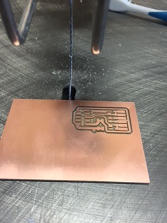
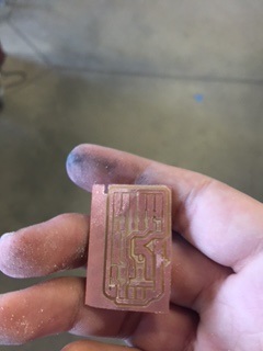
Note that on the last photo, one side is only cut partially. The saw grabbed the board and decided to toss it, so I decided to
stop and reduce the risk that I will injure myself. I then moved on to soldering the FTDI cable and other components to the board. The board schematics call for 600 ohm resistors, and thankfully, our Gestalt Nodes came with 4 of them If you did not receive any, you can use a value that is close to 600 ohms. Soldering was easy with the assistance of a clamp and some tweezers, and the result was quite appealing.
I could now
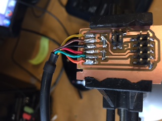
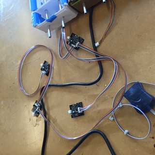
connect the boards to a computer. Never, ever, connect the power until all connections have been made, and never, ever disconnect the nodes while the power is on. First, run one of the cables we assembled from the connector board to one of the gestalt nodes. The input header is at the top of the board, plug the cable in here, connecting ground to ground, VCC to VCC etc.
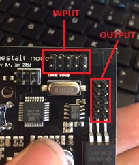
If you wish to chain multiple boards together, use the output header, and your connector will be similarly oriented.
Now connect the stepper motors to the nodes. The connection is keyed, so you shouldn't have to worry about orientation.
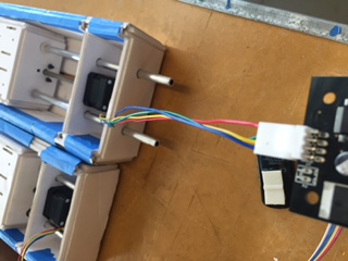
NOW you may connect power to the nodes. Connect a 12V power supply to a 2x2 pin connector. Remember which line is positive and which is negative. If the wire is thick, you may have trouble clamping the connector. Check with a multimeter for shorts between the wires. Now connect the power supply connector to the pin header on the connector board, connecting positive to positive and negative to negative. If you connect it any other way, you will fry the boards or short the power supply. You can now move on to programming.
But in testing, I realized that there was no easy way to get the servos to run from a program. They required many dependencies to be installed on Linux, and there was no option that I could find for Windows that would run the Gestalt nodes. We solved this problem by using a commercial board (see why below).
Why we didn't use the nodes
Our decision to not use the nodes was both a result of
time constraints and the difficulty of using the gestalt nodes. The gestalt nodes require a very meticulous setup and are very easy to break (I accidentally broke one during testing). They also require the setup of many dependencies in Linux, an operating system that not many of us were familiar with, and did not have the time to get used to.
Instead of what most everybody else did (gestalt nodes) we used an off the shelf ripoff arduino mega with stepper shield to control the machine. This simplified the programming aspect and provided many forms of software that could interface with the machine that would not be availible with the gestalt nodes. If we had more time avalible, we would have made our own boards to control the machine instead of using the commercial board.
How it could be better
If we had a proper hotplate, like the ones found on most 3D printers, then we would have much more working space and a guarunteed flat surface, whereas the one we have is bowl shaped.
If we had a better method to store the batter, then the machine would be less messy, since a bag is not an ideal or easy to implement container. A higher quality printed pump (without gaps in the spiral component where possible) would reduce batter leakage as well.
Files
Connector Board (yes, it's full size) modified from this page: