Home
Biography
Projects
Final Project
Electronics Production
Process of Production
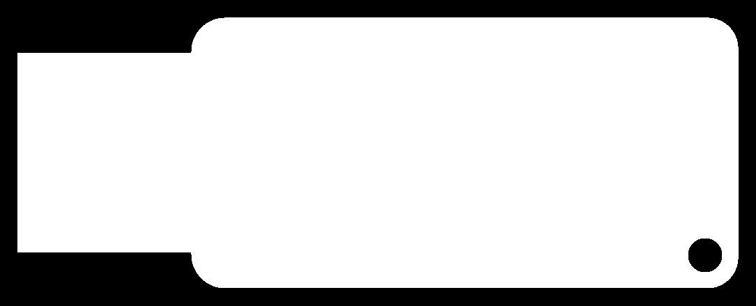
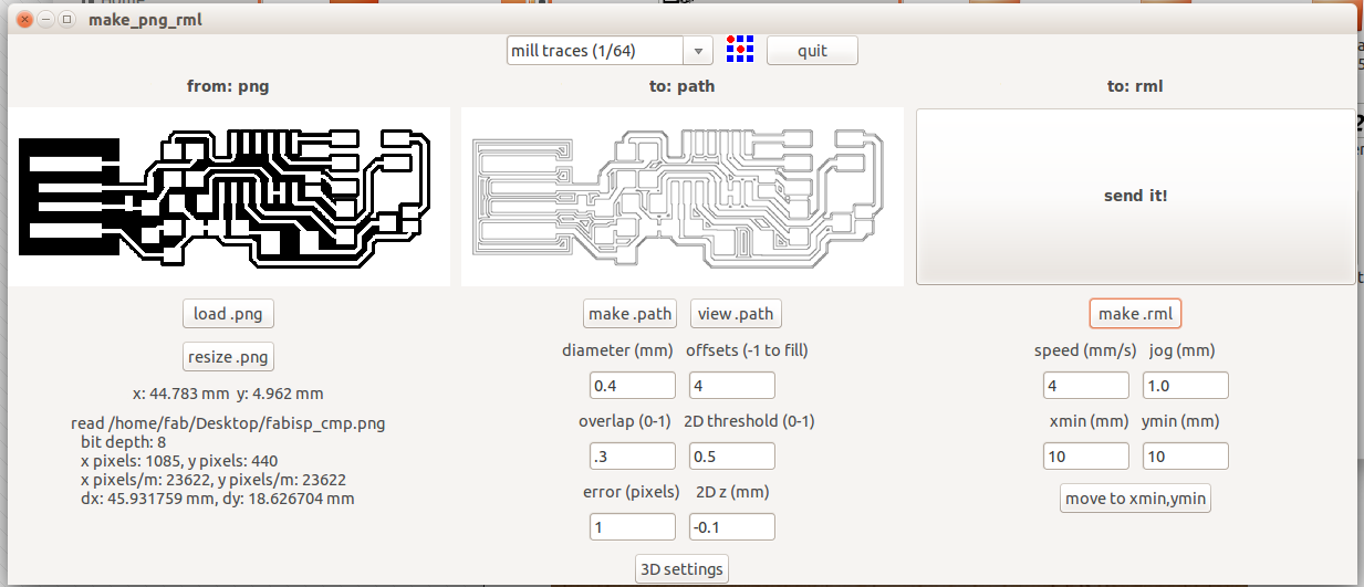
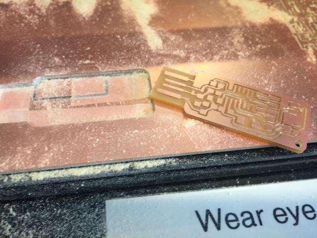
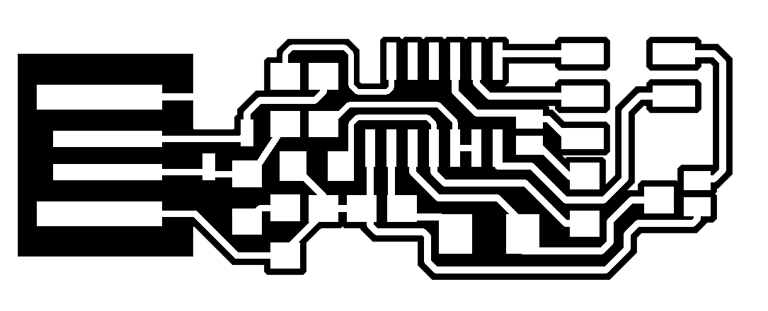
I decided to make Andy's USB keychain FabISP design. I liked this design because of its supposed portability. I started by downloading the PNG files to my flash drive from the website. The PNG files control the location of the mill traces and cutout locations. Under a normal production enviroment, you would design the board in place of this step.
Process
- Make sure you have a good milling (traces) bit. Otherwise, the edges of your traces will be rough or will be torn up.
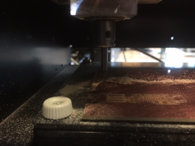
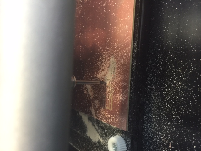
- Zero the milling bit. Do this by setting the X/Y postioin in the FabModule and re-seating the bit so that it is high up in the bit chuck. Then manually (with the machine controls) lower the bit until it is almost near the board. then loosen the chuck screw and lower the bit until it touches the board as shown (I showed the drilling (cutout) bit photos, they looked better, but there will be no differences in the method used for the milling (traces) bit):
- Then load the milling (traces) file into the FabModule. You first import the PNG and select overlap settings suitable to your soldering skill level in the "make path" section. You also need to select the milling pre-set fot the milling bit. Usually the bit will be 1/64 inch for milling the traces.
- Create the .rml file. you may have to play around with the settings, because too fast will break the bit and too slow will tear up the traces. Try to start too slow, because bits are expensive and boards are not. You can now send the .rml
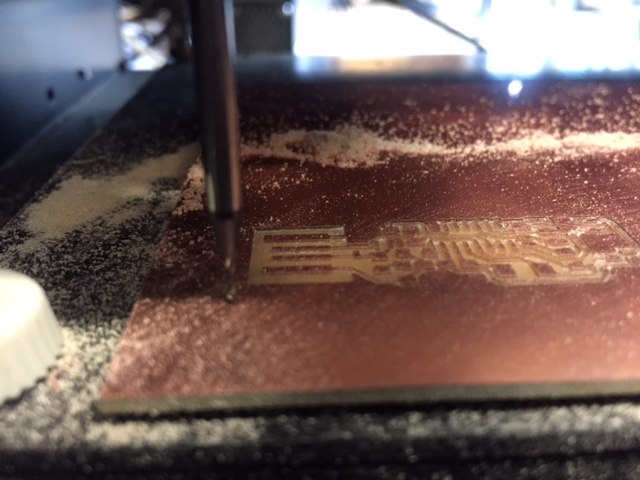
- The machine will begin automatically, so watch your fingers/hair/clothing. It is a good idea to keep the path of the mill clear of debris with a toothbrush. Yes the photo is sideways, but it's Apple's fault for making a crappy camera app.
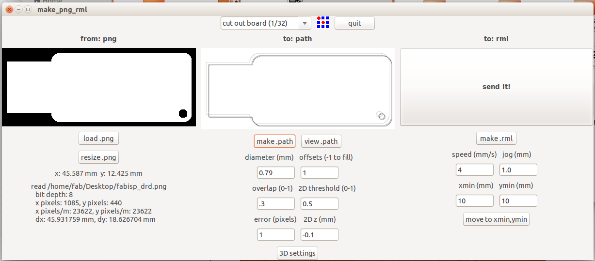
- After the milling is finished, you change the bit from the milling (traces) bit to a 1/32" drilling bit used for cutting the boards out, using the same process for zeroing out the board as described earlier.
- Follow the same process loading a milling file for the cutting file, just make sure to select the drilling pre-set. Note that some designs may use more than one drilling file, one for the through hole components and one to cut the board out.
- The drilling process is messy, so I reccomend using the toothbrush.
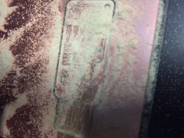
- you can now gently pry the board out of the stock (assuming it didn't fly out after it was done with the last bit of drilling).
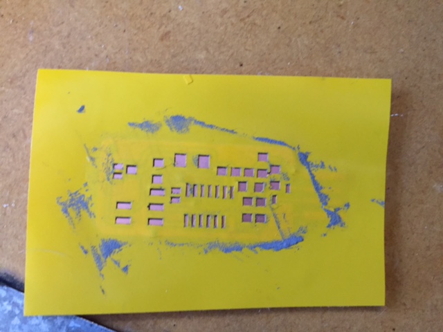
- You can now begin soldering components onto the board, but only after you clean the mill. I used Kadin's solder paste approach to soldering, as it removes the pain of individually soldering each piece to the board.Shown below is the solder mask Kadin designed for this project applied to the board.
- After applying the solder paste, you can attach the components to the board after removing the mask. I have learned not to press down on the components, as that causes the solder paste to bridge to other pads.
- After adding the components, you can use a hot-air station to solder them, but a soldering iron might work as well. The heat activates the solder paste, soldering the components to the board.
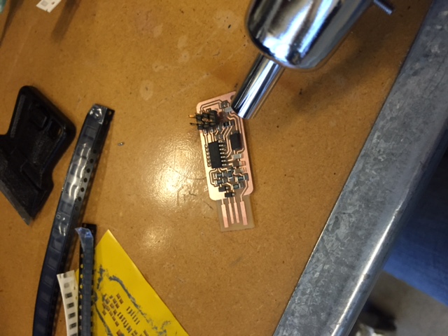
- This model needs to have some pads soldered seperately to the ground plane, so I used a soldering iron and some wire solder to do that (not shown). I also added some solder to the USB contacts because the board is a bit too thin for a USB port.
- To program the ISP, you need to boot into Linux and install AVRDude. As you can see, it was already installed on this computer. Full instructions to install can be found somewhere on here.
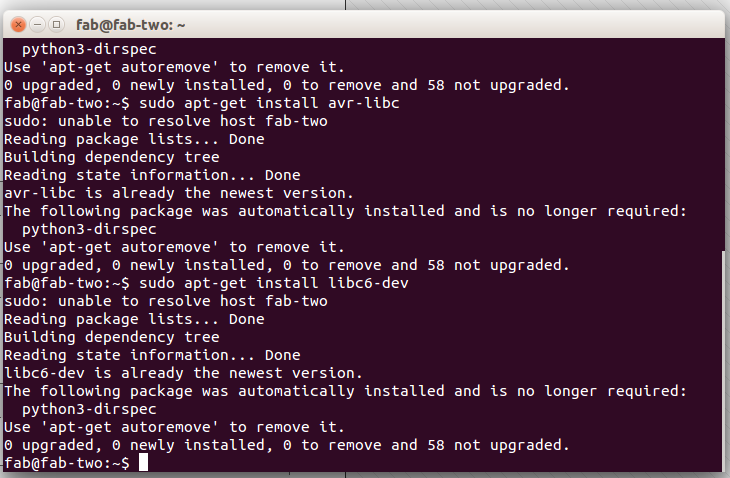
- To program the ISP, I followed the instructions on the previous link.
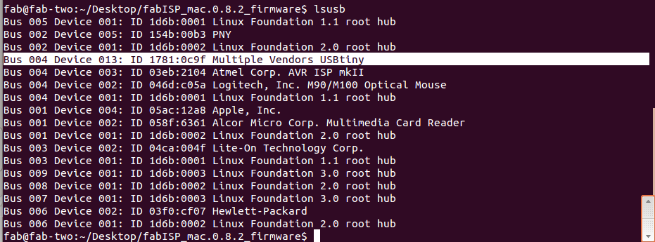
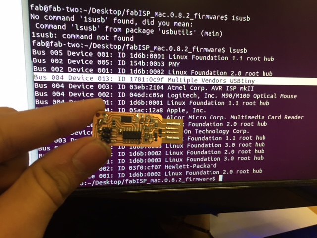
- To test the USB after programming, type
lsusb into the terminal. A list of USB devices should appear. If you are successful, your ISP should read something like Multiple Vendors USBTiny
- Your USB FabISP is Complete
Files
Mill
PNG
 Drill PNG