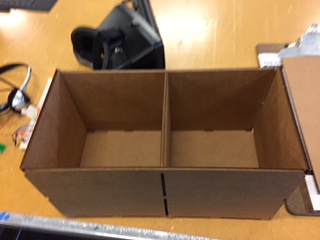
This week I decided to design a crate for my robotics team next season. The crate will have a compartment to store the robot and a compartment to store tools and snacks. The exterior dimenstons of the box will be 20 inches (a little less than 2 subway sandwhiches) by 20 inches by 40 inches (a little less than 4 subway sandwhiches). I chose these measurements because the maximum size every year for the robot is 18 inches (1.5 subway sandwiches) cubed, and I wanted half an inch (about one centi-whatever) of extra space around the robot.
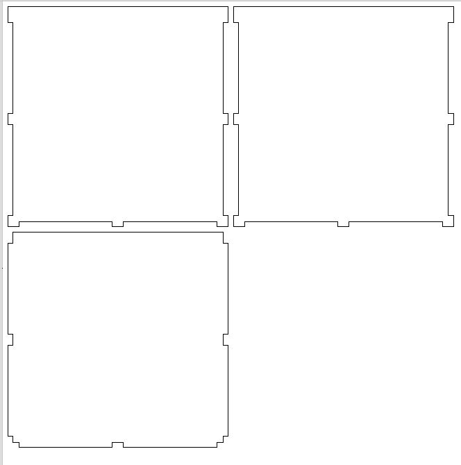
I designed the box in Aspire, which allowed precise design and was easy to export to the shopbot files. To design the box I used the process decribe on the CAD page, but this time I was assisted by a calculator that I threw together in google sheets.
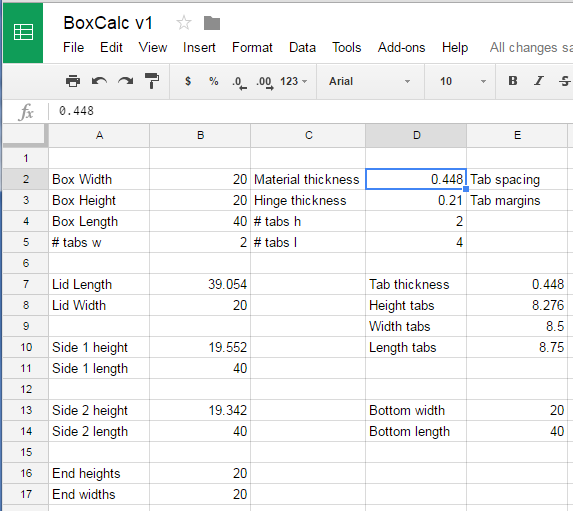
The calculator calculates the dimensions of a press fit box with a hinge, including tab lengths. The calculator works with all measurement systems (yes, including the sandwich system), just remember to keep your units consistent.This has helped me design a prototype box out of cardboard on the lasercutter.

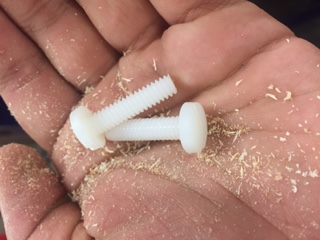
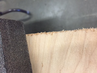
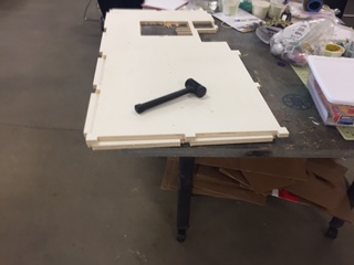
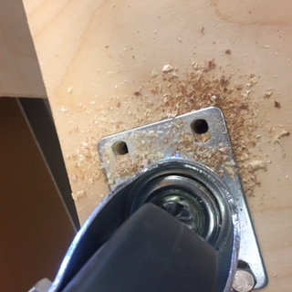
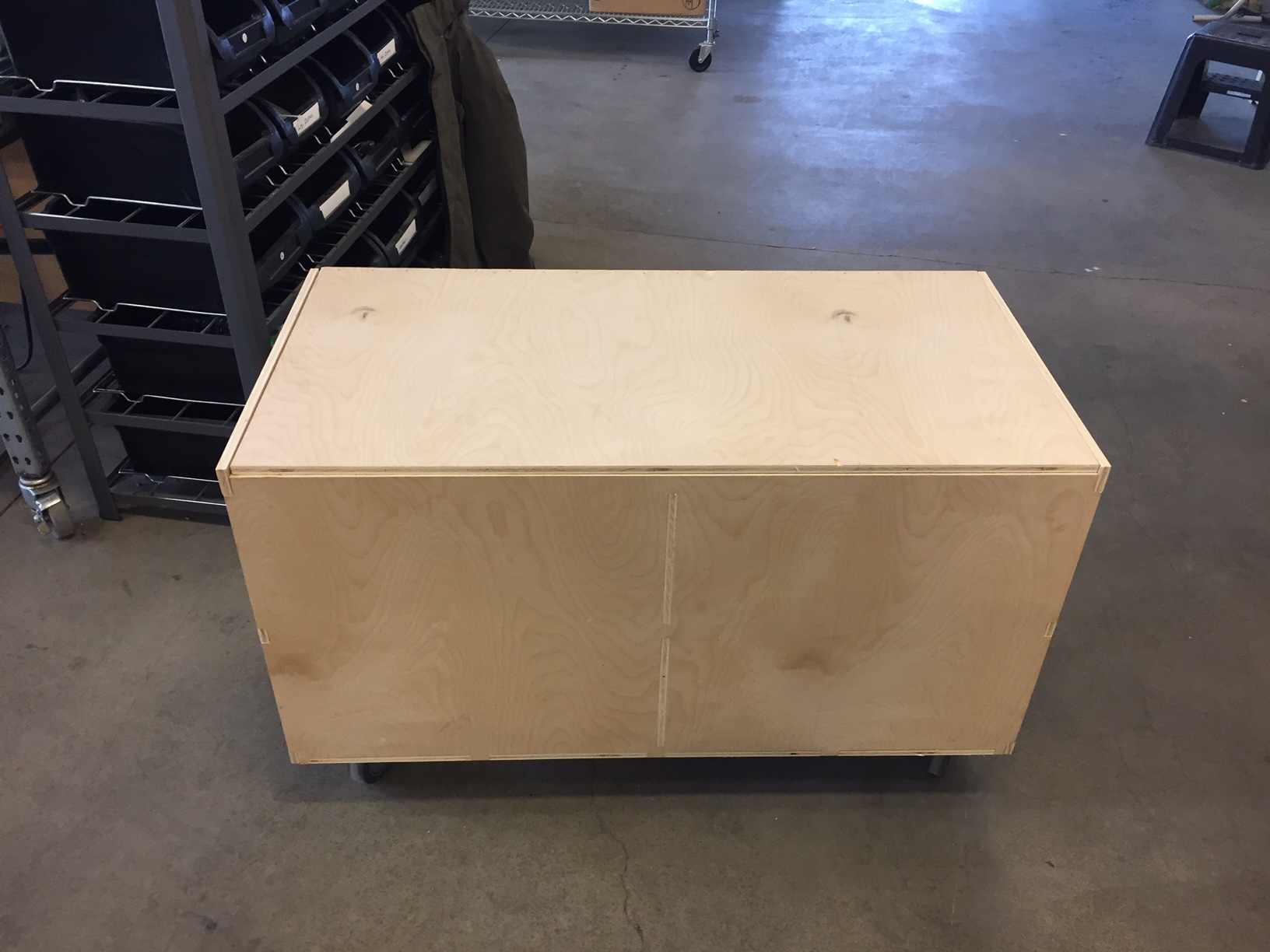
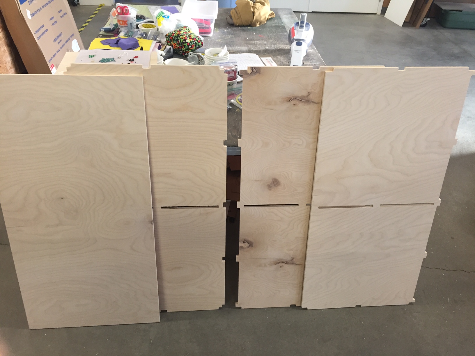
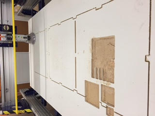
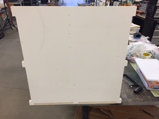
After I confirmed that my method worked, I proceeded to scale that model so that I could cut it out of scrap plywood as a test using the CNC mill. The test cut would be larger than the actual box, but it was helpful to know that my design would work on the CNC mill. I found out that I would have to file down the interior corners, because of the limitations posed by a circular bit cutting straight corners. the test piece was easily assembled with a rubber mallet.
After that, I measured my final material with a pair of calipers, and inserted the value into my calculator. With the calculated values, I was able to design the entire box within several hours. However, this took a bit of mentally adding and subtracting decimals, so your milage may vary. Make sure the spacing between your parts is at least twice the width of the bit you are using.
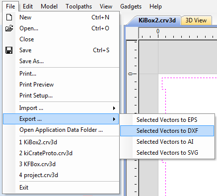
Loading the file onto the CNC machine (in this case a ShopBot) is a several step process that has to be followed carefully. First you select the parts in Aspire. navigate to File>Export>Export Selected Vectors to DXF and select the option. If you designed your object at the computer you control the ShopBot from you can skip the export. It is a good idea to have the individual vectors welded together.
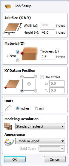
Move the DXF to the ShopBot computer and open aspire. Start a new file and make sure your material size is the size you are using and that the origin is at the top of the material and at the lower left corner. The correct settings for a 4' by 8' (4 sanwiches by 8 sandwiches) board are shown below.
I ran into problems with the correct X-Y origin. If you set it to the top left, the shopbot will attempt to go out of bounds. I can only imagine what horrors would result if the Z origin was set to the bottom of the material.
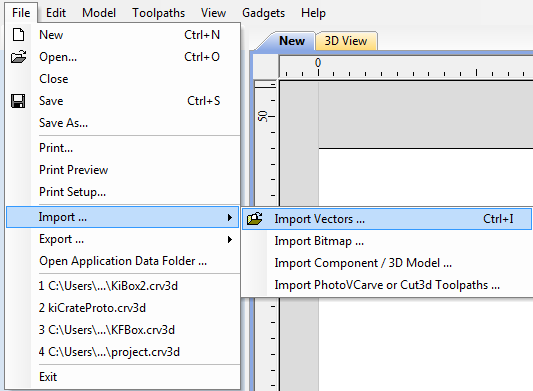
Import your DXF into the new aspire file using File>Import>Import Vectors You can also use Ctrl+I. The vectors may not appear inside the workspace, so move and rearrage until it works. This is a good time to double check that the spacing between parts is at least twice the diameter of the bit you are using. Try fitting as many projects into one sheet as you can, because half inch (one centi-whatever) plywood sheets can be as much as [insert large monetary value here].
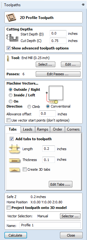
After arranging your parts, open the toolpaths tab found at the right of the screen. Select the Profile Toolpath option. In the Profile Toolpath menu, check the start and cut depths. Make sure the start depth is 0.0 and the cut depth is 0.01 to 0.05 inches greater than your measured material thickness. This prevents the machine from cutting too shallow, but too deep ruins the tabs.
Next, check that the setting for your cutting bit are correct. Set the diameter to the exact diameter of your cutting bit and the spindle speed to 18000, or a comparable speed for your machine, which can be found on a sticker on the spindle, which should still be there. Set the number of passes to 6, because less passes = less depth = less friction = less fire (and fire = bad). Theres probably a few other parameters worth looking at, bit I didn't bother looking.
Now you need to determine if you need tabs. Small objects definitely need tabs, but anything about 20 inches square (about 2 sanwiches square) also need tabs, like the ends and the divider of my box. The correct settings for tabs shoud be about [see photo below]. Add the tabs, and make sure that you don't get way too many tabs, if you do, try re-welding the vectors or joining open vectors.
Now press calculate and check that everything is correct. Now close the preview and re-open the toolpaths tab. Select the Save option, which looks like a floppy disk. Select the .sbp option for your choice of measurement units. Name and locate your file somewhere you will remember.