Abstract
This week was about agreeing on a machine to build, modelling and producing a prototype working mechanically.
One day I will be involved in a group where everything works smoothly but it won't be this project.
Some of the question raised were:
- How to work together?
- How to exchange?
- What are the tools to preview mechanical interactions?
- How to document the group production?
I mainly used 1 workflow:
Trello > Slack
My biggest achievement: Making everyone use Slack + Trello
My biggest struggle: Getting everyone involved
Chronology
| Thursday | Friday | Sunday | Monday | Tuesday |
|---|---|---|---|---|
| Brainstorming with Yassine | Brainstorming with Yassine and Alexis | Documentation | CAD library | Documentation |
| Unboxing | Sketching | Algodoo test | Documentation | MTM files reworking |
Setup
| Softwares | Fonction |
|---|---|
| Algodoo | Modeling gears and movements |
| Slack | Group discussion |
| Discord | Group discussion |
| Trello | Group project management tool |
| Rhino + Kangaroo 0.99 + 2 | Gear design |
| Solidworks | Conveyor design |
Skills acquired
Asssesment validation
Group tools setup
One of the hardest part of a group project is to have good communication channels. So I created a Slack channel: #machine -Slack being already used by our region- dedicated to our machine project regrouping our instructors and us three. To have a place to store ideas/links, to dispatch taks I also created a Trello table. Ideally Trello and Slack should be replaced by open-source management tools. The Slack and the Trello were then synchronized. Slack was added as Power-up in Trello and Trello was added to slack as app, then invite in our #machine channel.
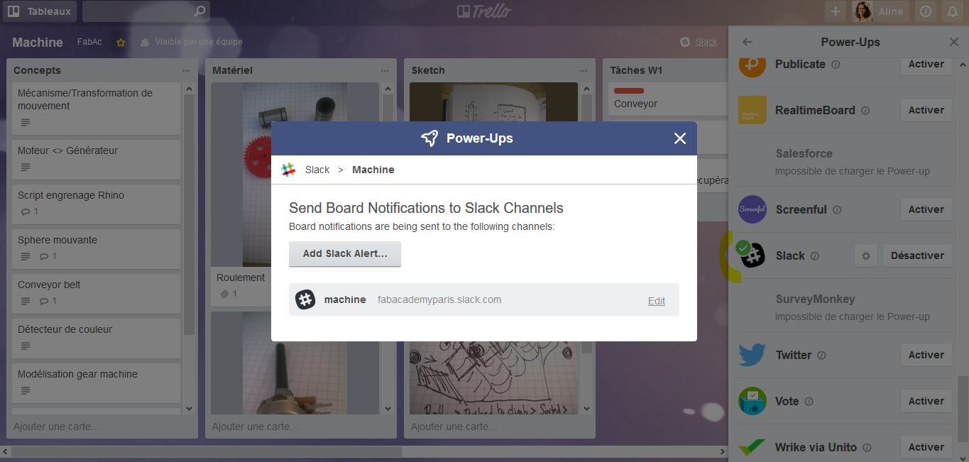
adding Slack to Trello
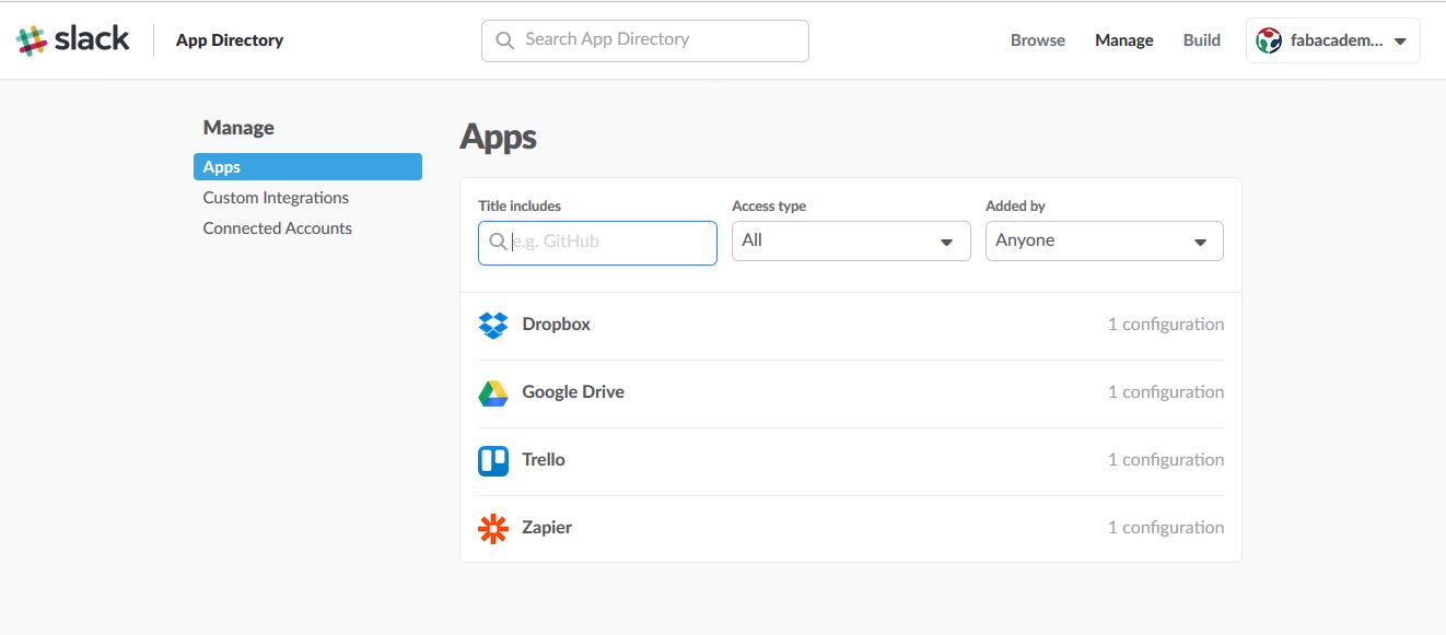
adding Trello to Slack

Trello notification in Slack
But despite the care taken in establishing those channels, I was the onl;y one to feed them...until tuesday!
Documentation
I took care of this aspect this week but I am aiming at taking this task in turn (1 member taking care of 1 week). At first I considered turning every day but as we decided to go for the usal git repo storage we are constrained by Thomas push frequency.
Documentation consists in:
- recording every step of conception
- retrieving source files
- writting the group html
So I took my page template and created a groupproject.html at our git seed. I took care of copying the vendor, css and js files at the seed. A file was created to store the related images(groupproject_im).
Merging ideas
The first task was to get together and agree on the machine purpose. To do so we decided to all pick a concept we wanted to work with and find a machine that regroup all the concepts. Those concepts will also help us to divide the work.
| Member | Concept picked |
|---|---|
| Yassine | Gears and movements change of direction |
| Alexis | Conveyor |
| Aline | Energy harvesting (motor > generator) |
On Thursday only Yassine and mysef were at WoMa as Alexis belongs to another fablab in the south of Paris. We took several roads.
One of them was Hacking motors:
- Making a generator out of a stepper motor was one way of hacking motors
- Using the motors as moving ballast.This could have been used to build a spherical bot.
The other aspect was Gears:
- for an easthetic purpose such as shown in this video which also displays a nice Grasshopper workflow:
Another was Energy deperdition: We kept the motor into generator concept and tried to merge it with gears and movement. We thought about a mechanical machine which would display the retrieved energy after several gears. On Friday Alexis joined us for a morning session. He added his concept to ours; he is keen on conveyors belts.
So a new axis was Conveying and sorting: Alexis showed us videos to help us understanding all the different conveyors types possible, such as the Lega contraption competition.
Alexis also has multiple unused colour detectors at his lab so we looked at combination of conveyor and sorting mechanisms such as:
Material at disposal
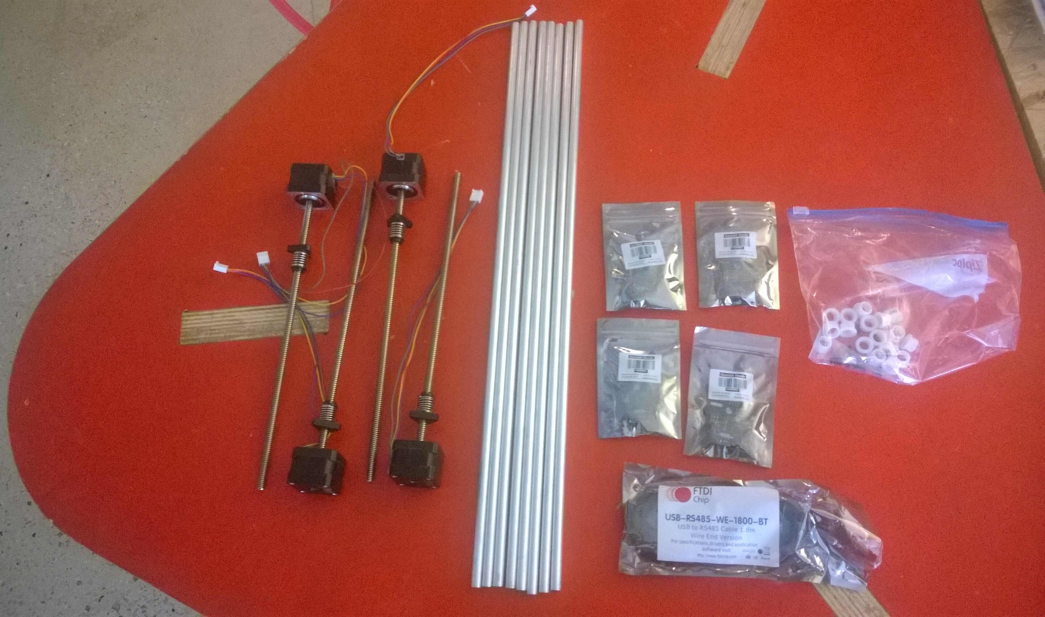
The material available also guided our reflexions. So we unpacked our machine box.
unpacking
FabAcademy table
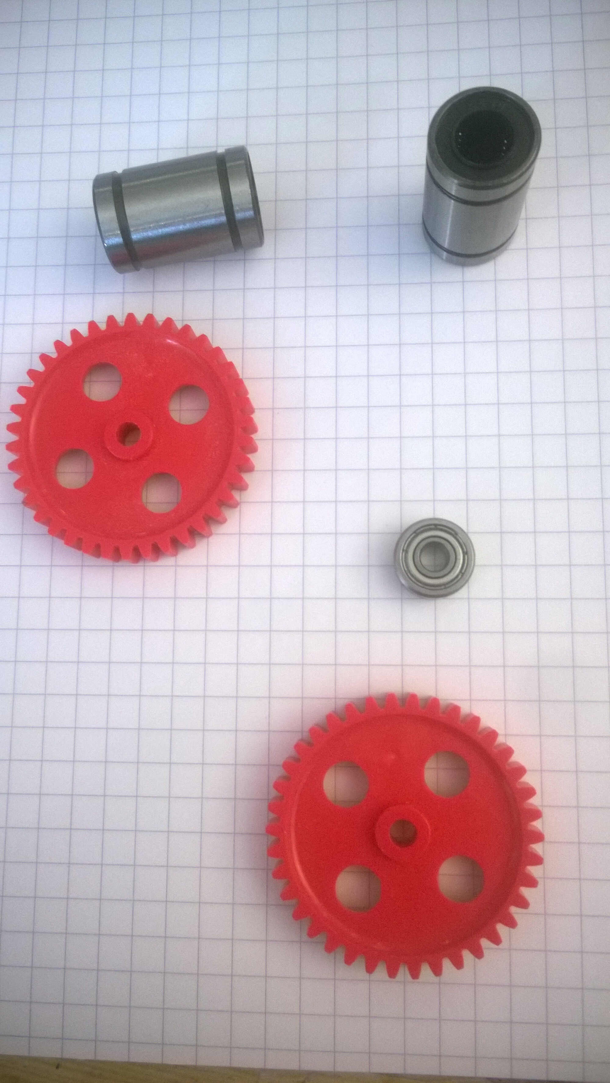
We also looked around at Woma for machine material. We found gears, ball bearings, a potentiometer, a 3d printer open belt and some 3D printer motors.
WoMa stuff
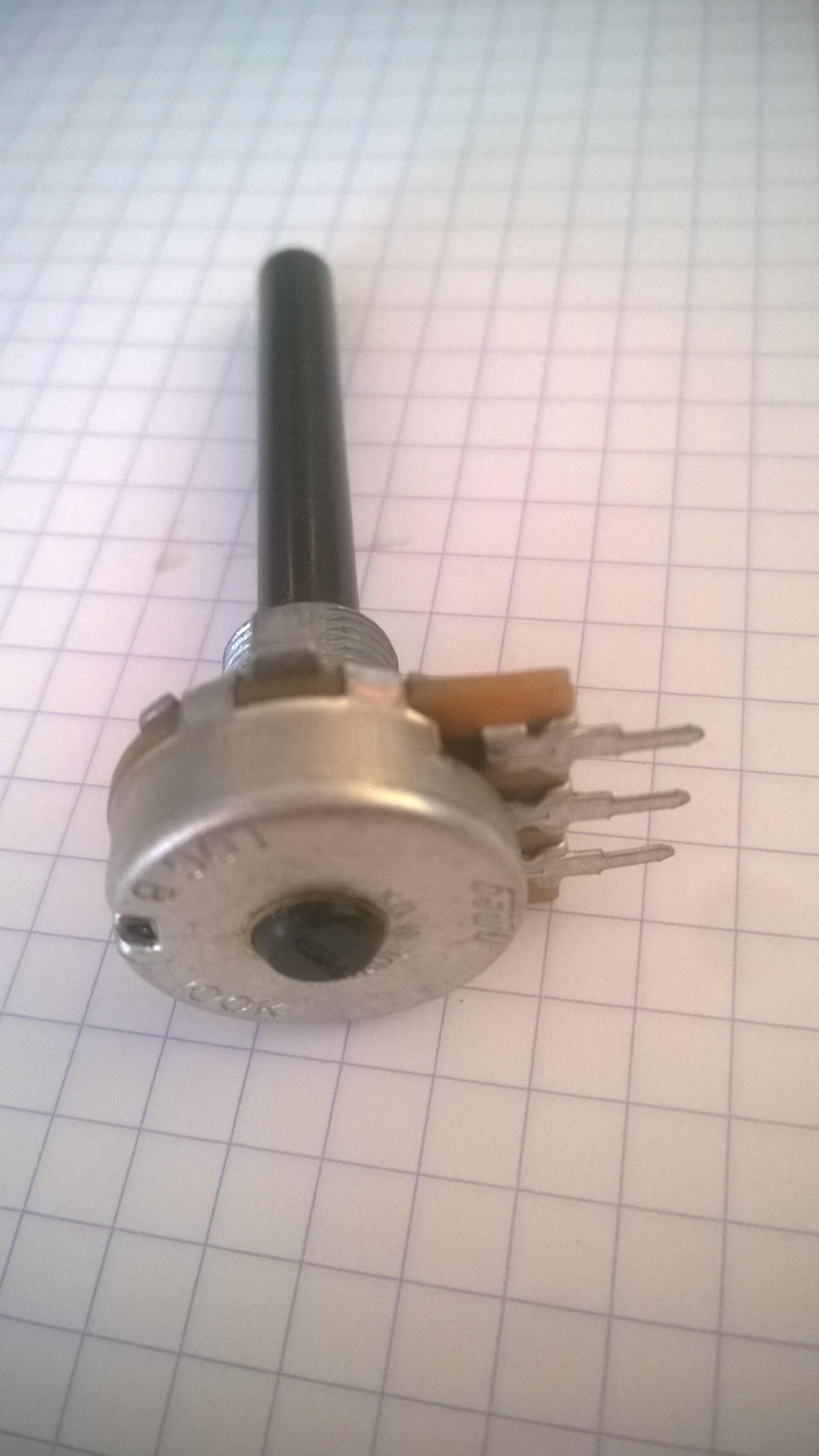
potentiometer
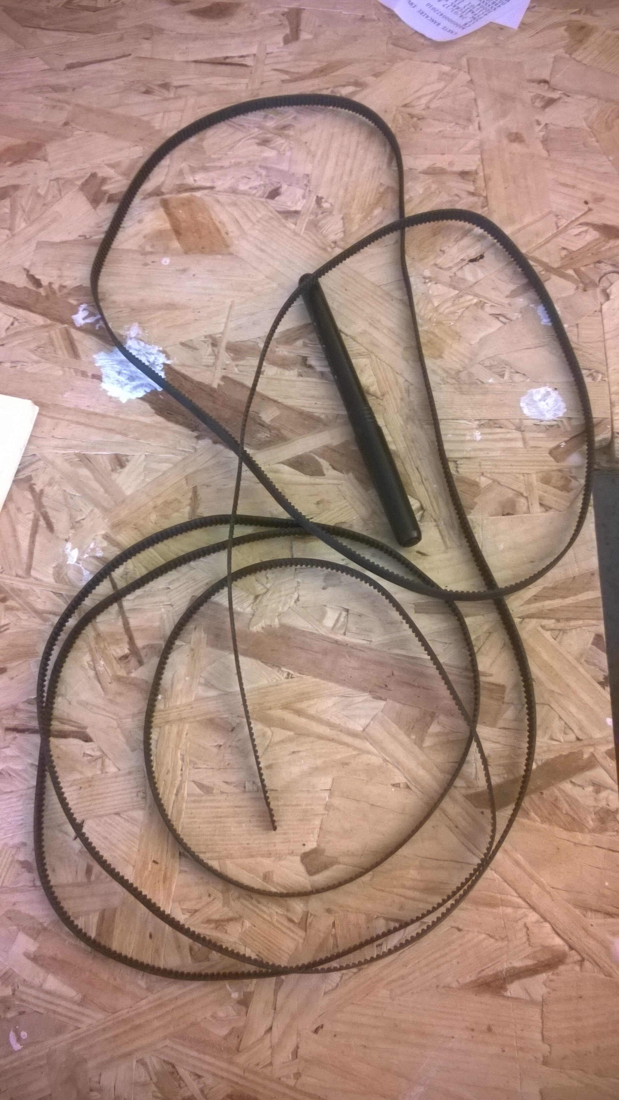
belt
additional motors
After this hunt and after discussing with Alexis our list of material was the following:
| Material | Number | Model |
|---|---|---|
| Stepper motors | 9 -7 with axis -4 wires | RB step motor 17HDC1220-300N |
| Gestalt nodes | 7 | |
| Shafts | 14 | 9.53 mm diameter |
| FTDI cable | 2 | |
| Belt | 1 -open- | |
| Ball Bearing | A dozen | |
| Potentiometer | 1 | |
| Colour detector | 1 | |
| Colour detector | 1 |
Making the most of our material was also a central idea.
WoMa inspiration
I looked for motorized inspiration around the lab. 3D printers are particularly relevant as our Fabkit motors are 3d printer motors. A gel dispenser built at WoMa for a robotized arm shows us a great assembly example.
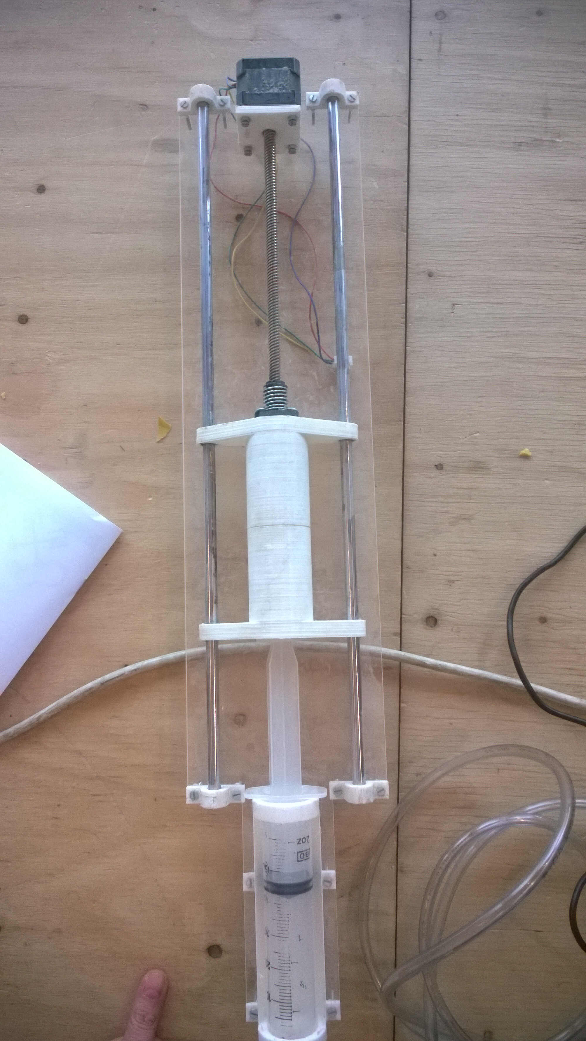
syringe
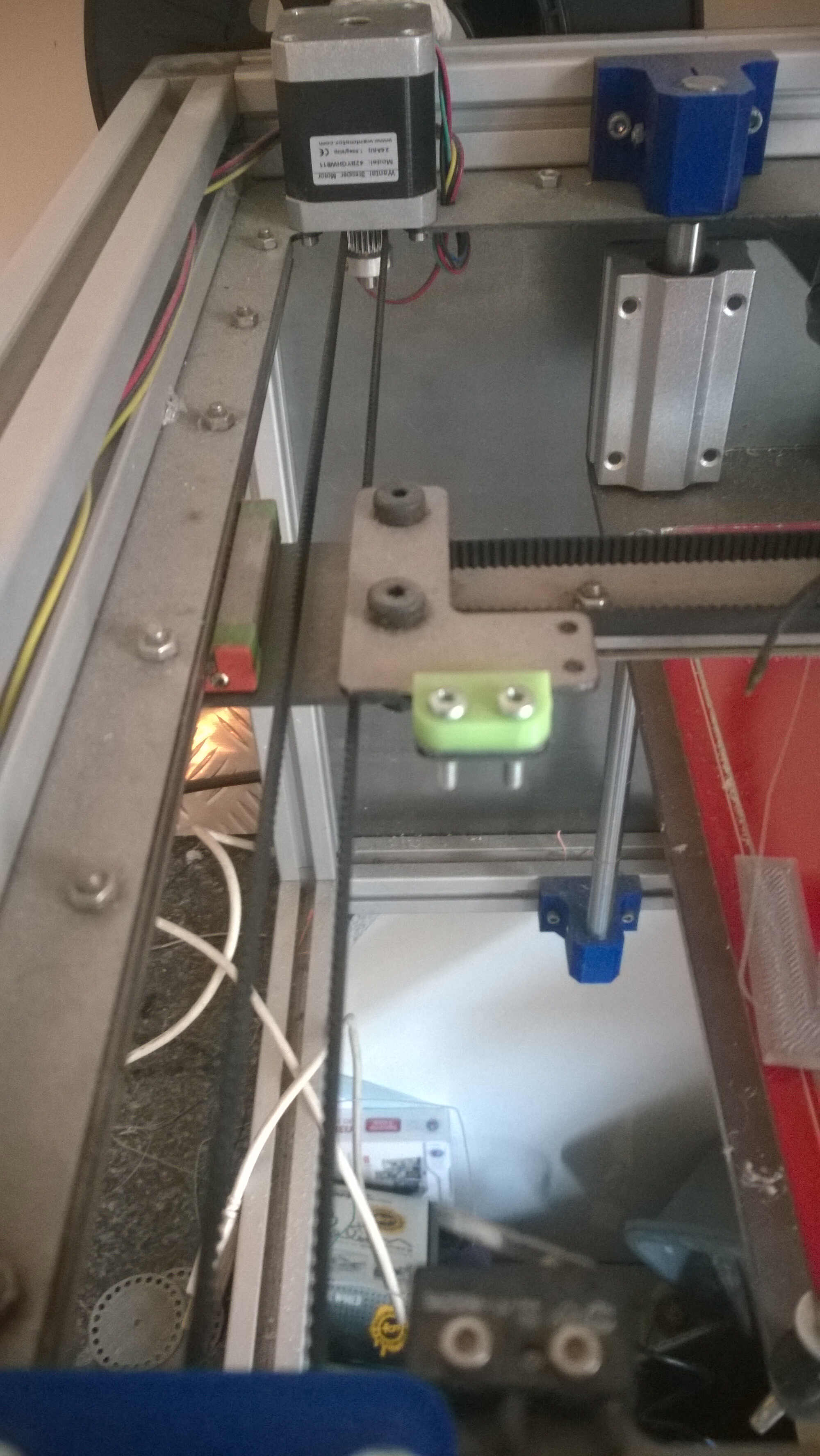
3D printer belt system
Handmade sketch
First we tried to draw some sketches.
Yassine's vertical conveyor
my machine representation
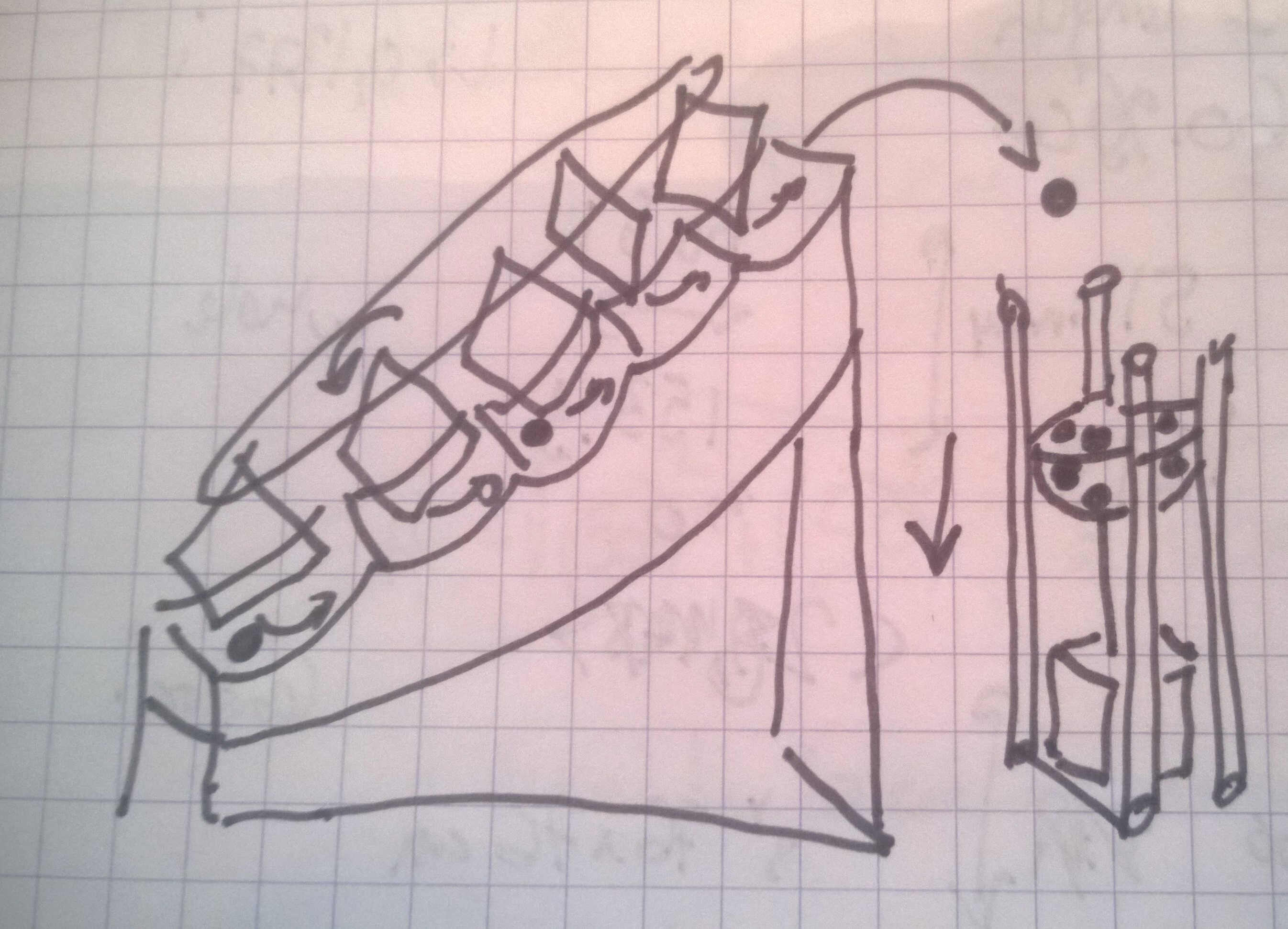
my collector generator
Meca modelization
Algodoo
Then we found a Youtube video made with a software called Algodoo. It can be used to model mechanism and displacement but it is limited as the distance can't be specified and as it's only 2D. Here you can see the results of the simulation of cinetic energy harvesting I did
3D pieces database
I also found a website where CAD models of commercial mecanism parts could be retrieved fro free.
Solidworks modular step
Alexis made a first model a step module with Solidworks.
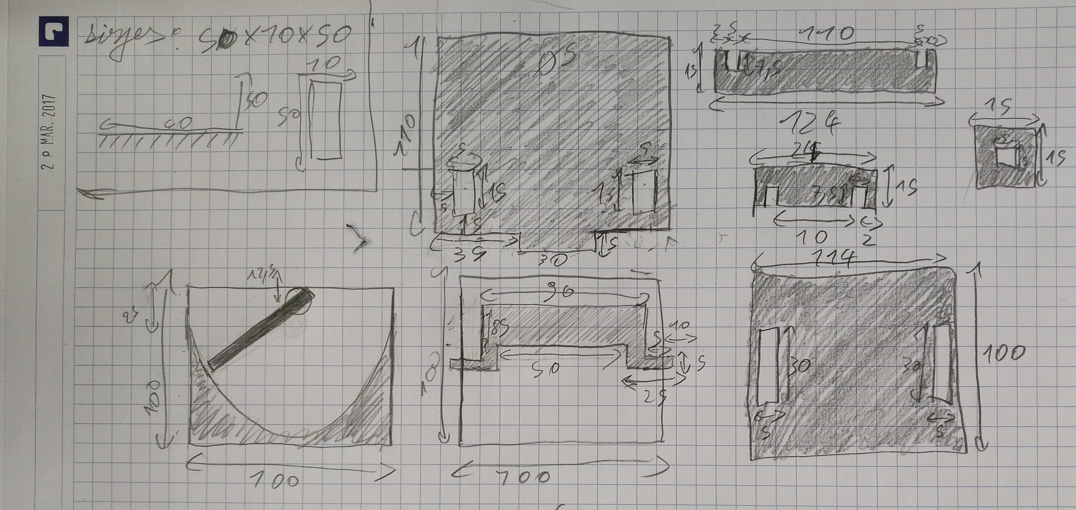
hand sketch
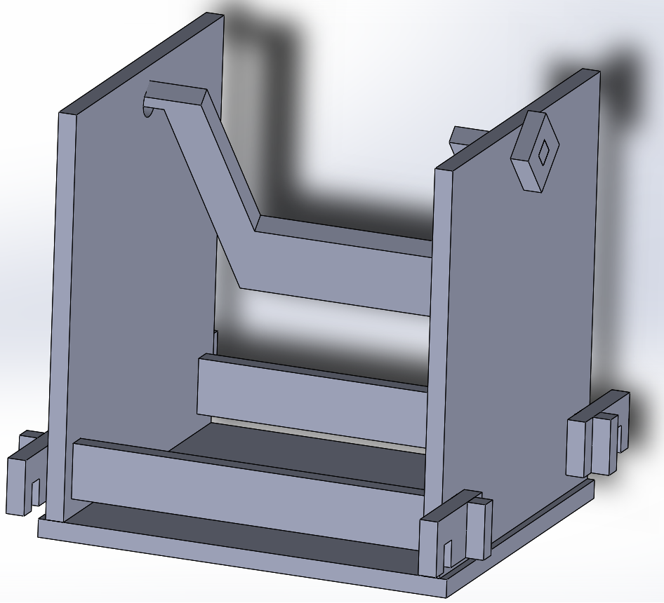
Solidworks assembly
Rhino+Grasshopper gears
Yassine created an infinity mecanism. He used Kangoroo physics, a Grasshopper pluggin.

mecanism assembled
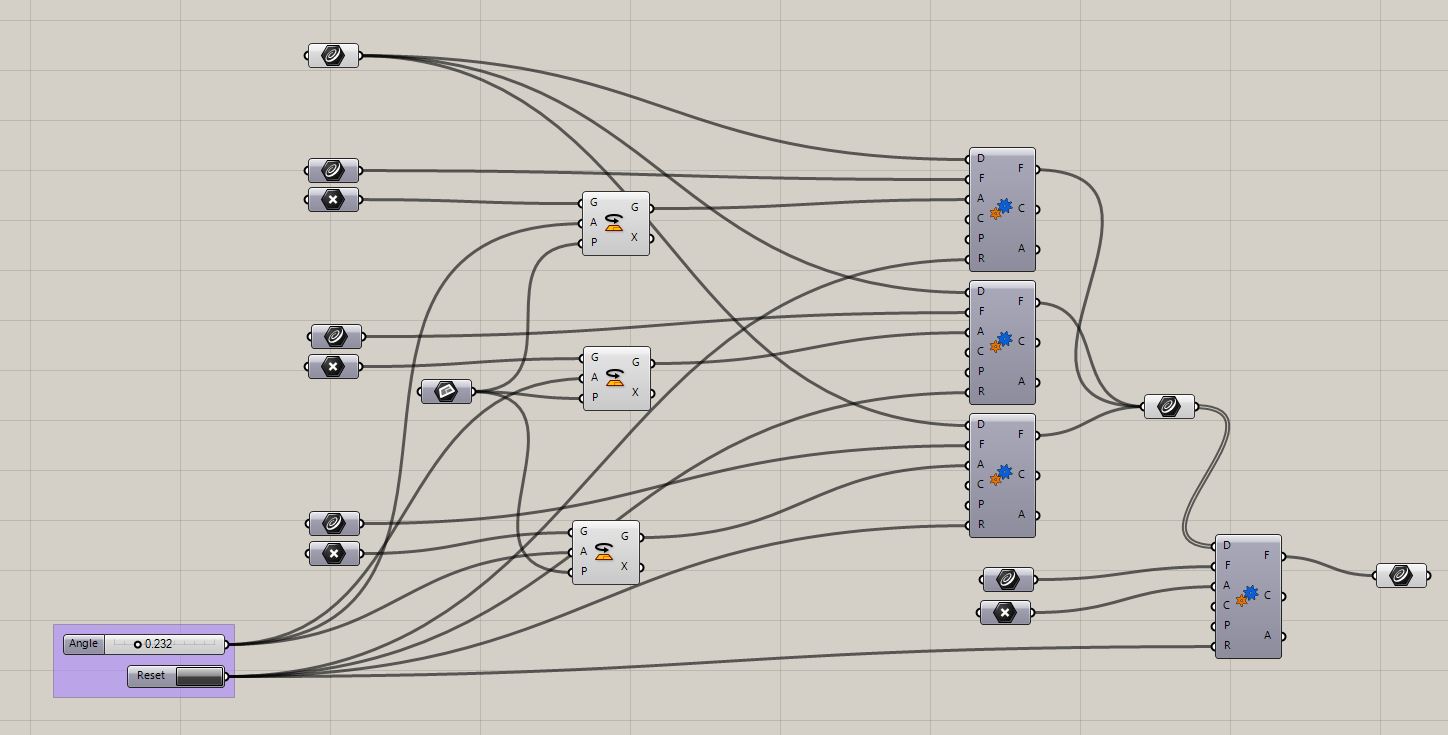
Grasshopper flow
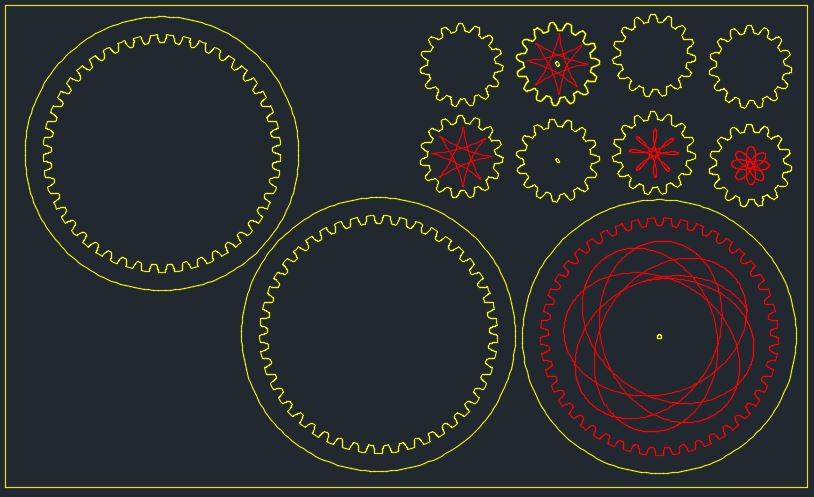
Rhino visualization -with trajectories
I installed Kangaroo to track Yassine's workflow down. I had some troubles doing so, the Kangaroo tabs didn't appear in Grasshopper.
To fix this, I went to Food4Rhino and downloaded Kangaroo Physics 2.2.1 and 0.099.
I unzipped them, I opened the components folder in Grasshopper (File > Special folders > Components folder) and copied the dll and .gha files here. I copied the UserObject files from Kangaroo 0.0999 in the User Object Folder (File > Special folders > User Object folder).
I made sure they were unblocked by clicking right on each of them going to their properties and ticking unblock.
I relaunched Rhino and the tabs were here.

food4rhino
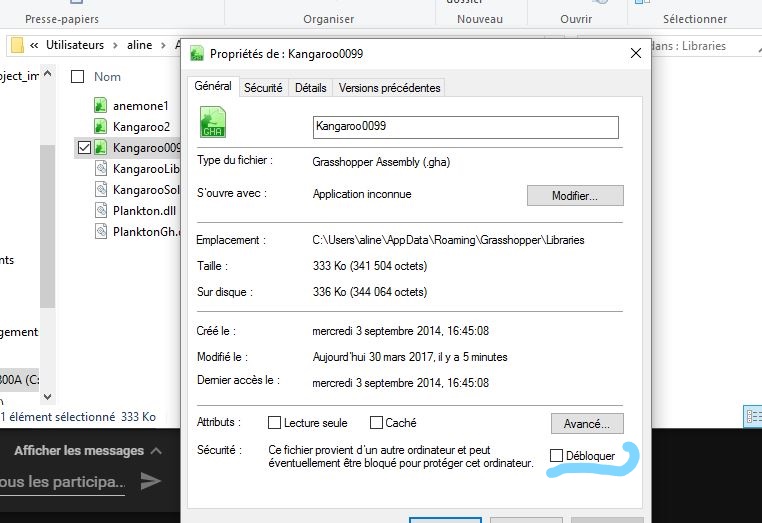
unblocking
Kangaroo tabs and gear option
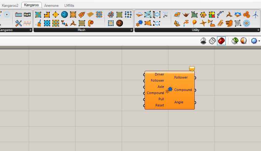
I tried to reproduce what Yassine did to simulate gears, using Kangaroo Gears option:
First I drew 2 tangent circles in Rhino then assigned them to 2 different curve geometries in Grasshopper.
For one of the circle I plotted the center and assigned it to a Point parameter in Grasshopper.
I added a Gear (Kangaroo > Utilities > Gears). I defined the cercle without center as the driver and the one with as follower.
Then I defined the Axle.
I defined the center of the follower circle as the geometry of a rotation (Transform > Euclidian > Rotation).
I created a Plane parameter that I set in Rhino as the plane of the circles. This was the plane of the rotation.
I added a number slider to define the angle value of the rotation.
The resulting geometry of this rotation was input as the axle.
A reset button was created (Normal state: False, Pressed state: True) and linked to the reset entry of Gears.
A geometry curve output was linked to the Gears result follower.
The creator of the gear option provided some examples that i was not able to open with my Rhinoceros version.
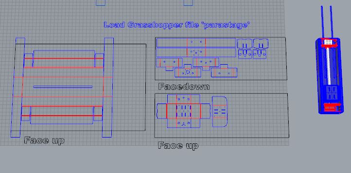
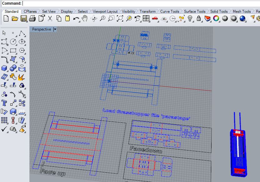
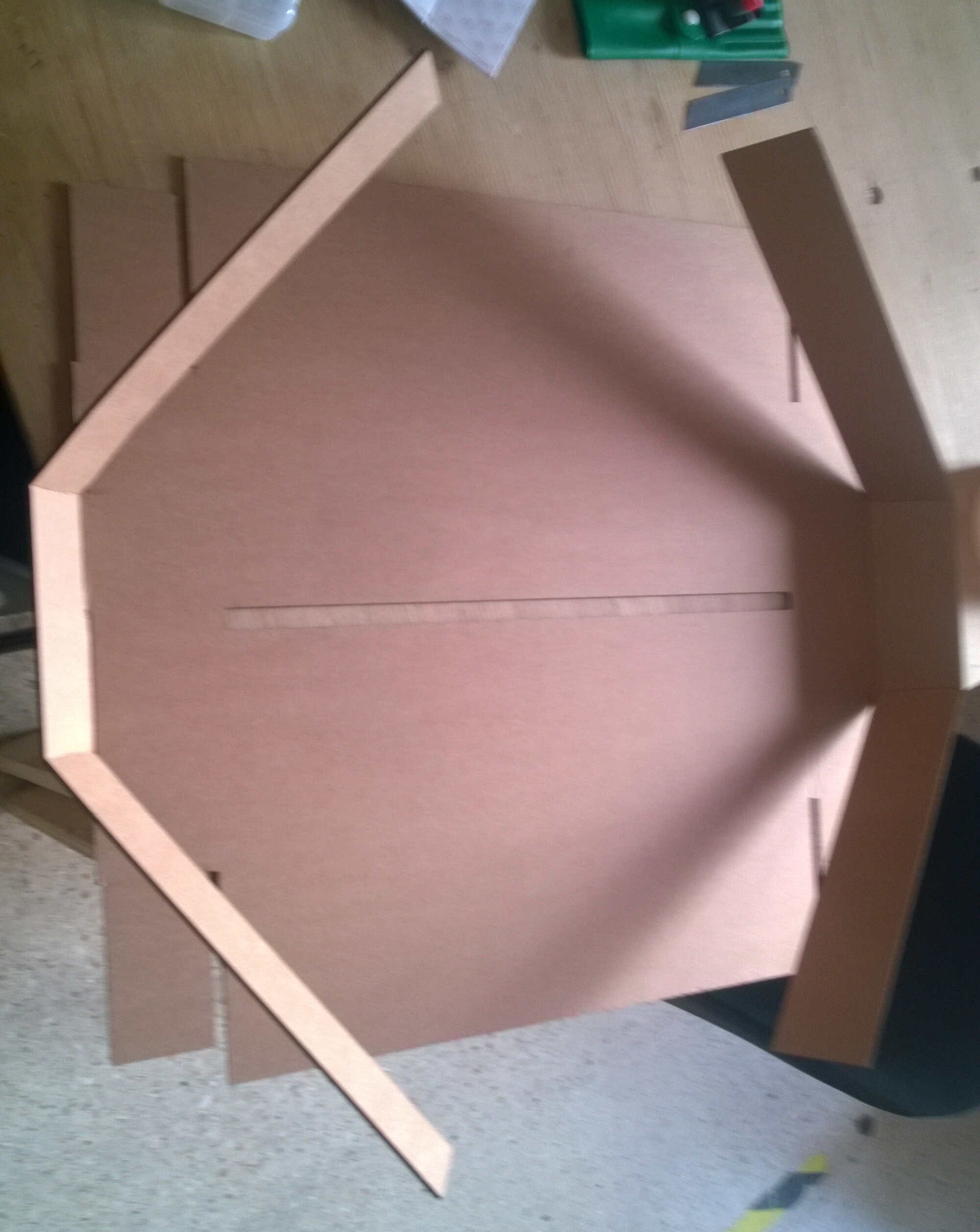
Cardboard stage
I wanted to reproduce Nadia's box to have a first built element. So I loaded the Rhinoceros/Grasshopper files provided. This file is a good way to learn Grasshopper: it is well organized, each part has its dedicated workflow and instruction are written on the display. At the top left there is a control panel, the main parameters were duplicated here and can be modified from there.
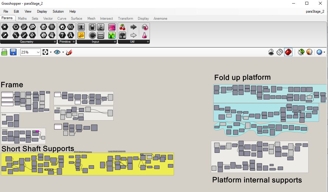
organized Grasshopper
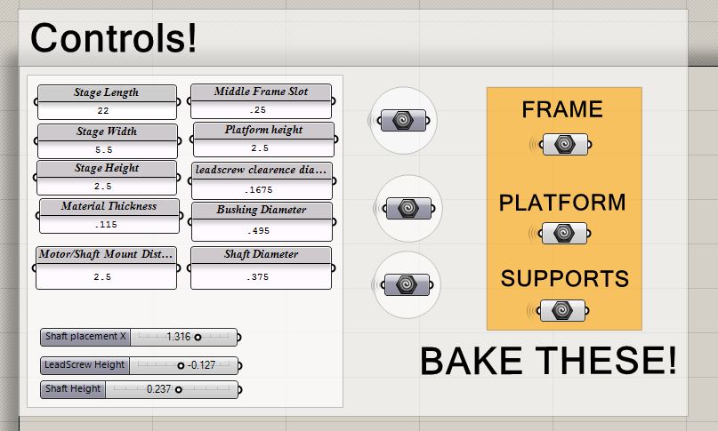
control panel
Rhino visualization
1. I didn't have cardboard of the same thickness
2. When baked all contours were blue so I had to manually pick the lines to fold.
3. Then WoMa didn't have enough cardboard for the whole structure
I postponed this production.
all blue
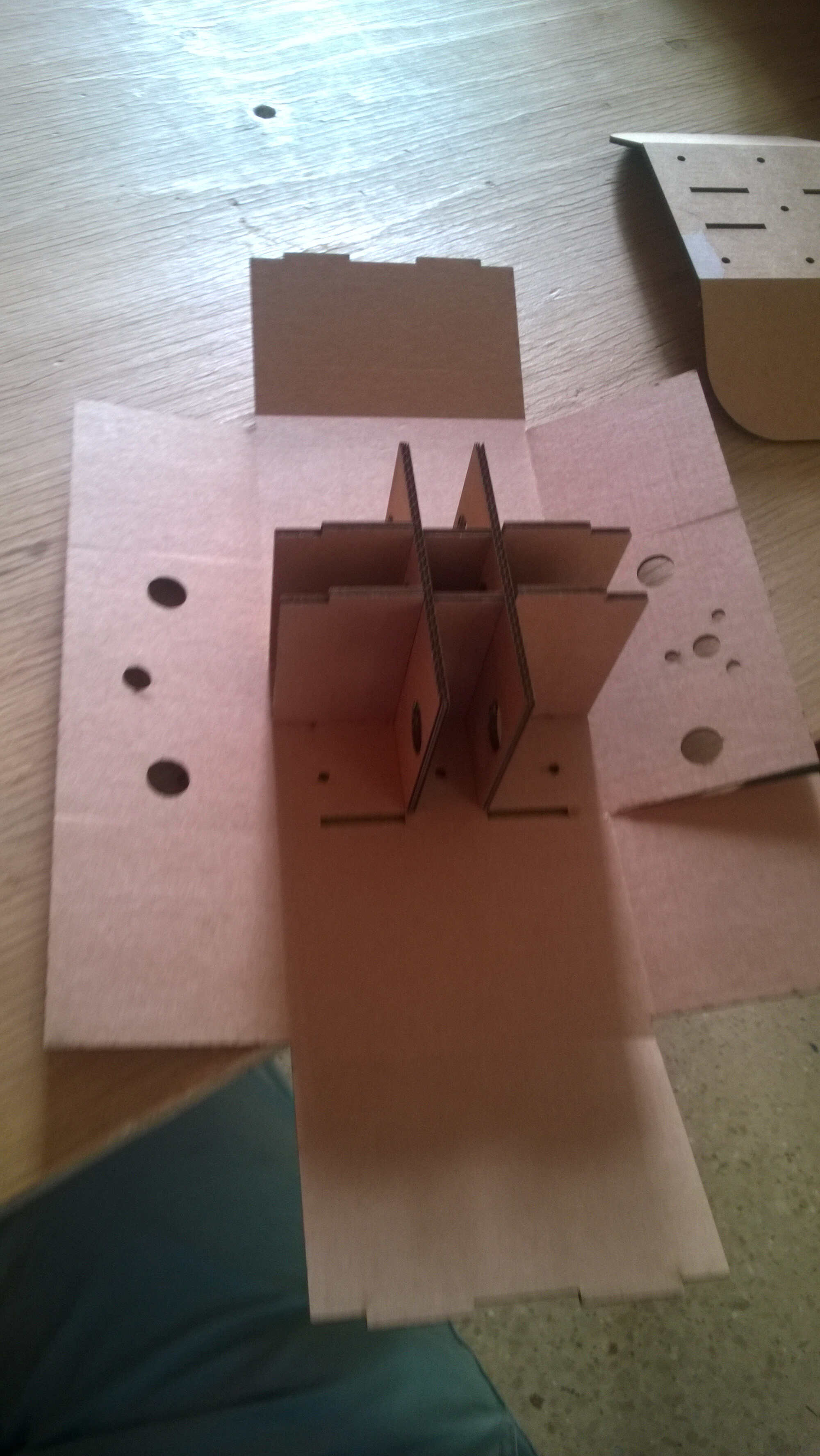
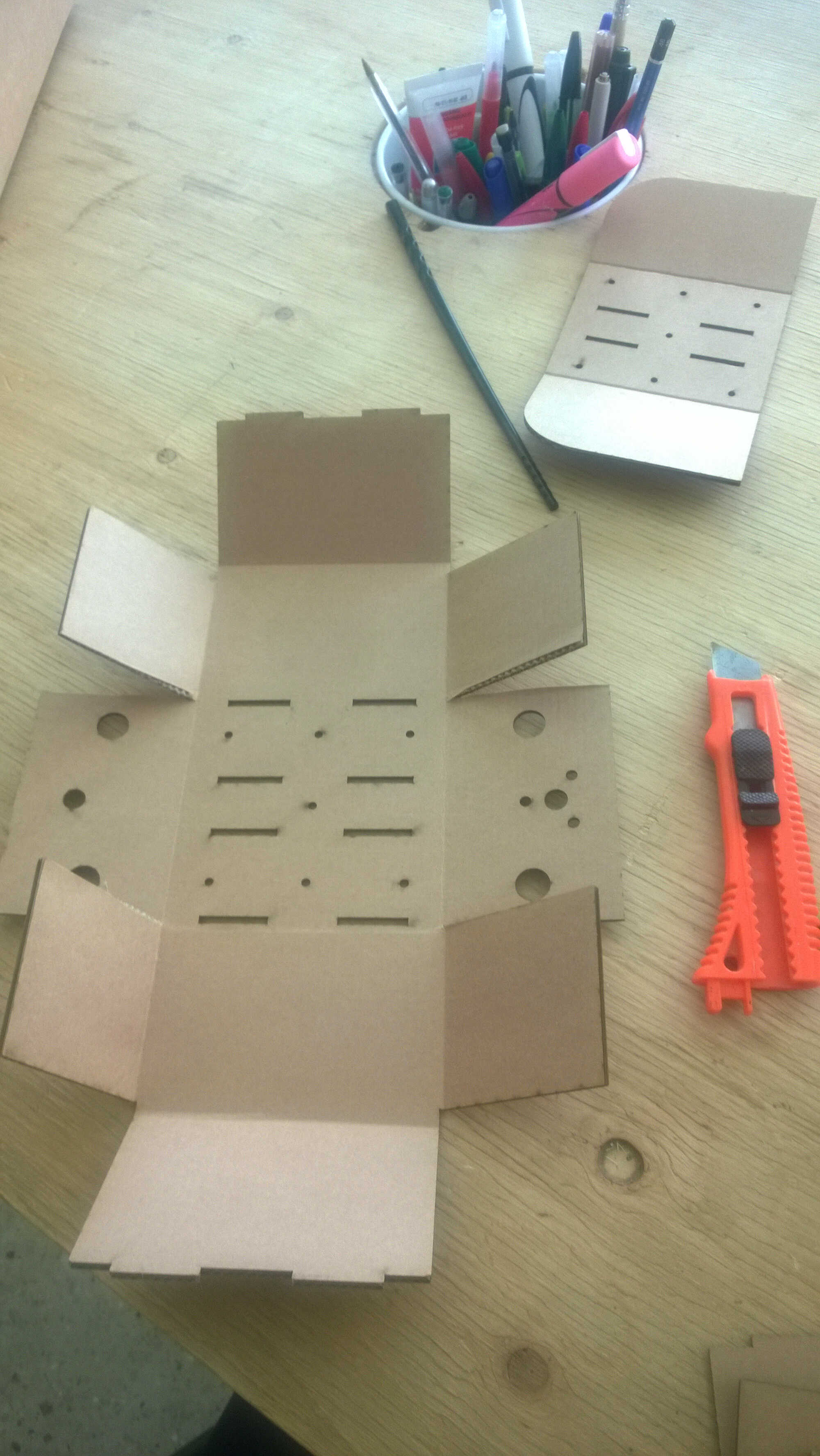
Weeks later I bought 3mm thick corrugated cardboard and tried again. I loaded parametric Rhino files, as I had the good thickness I didn't need Grasshopper. I have to say that I did not understand the face down/face up instruction. I lasered the moving part apart to test the cutting parameters. Alex gave me great tips, it worked at the first try. I couldn't fold the main piece in the right direction so I suppose I did something wrong. Maybe some pieces need to be lasered both sides. For the folding the gif was too quick for me. Thomas advised me to use a gif frame extractor. I chose ezgif as I could enter an url. I simply CR on the gif to get its adress and I could obtain all the frames in .png.

cutting parameter

grouped cutting
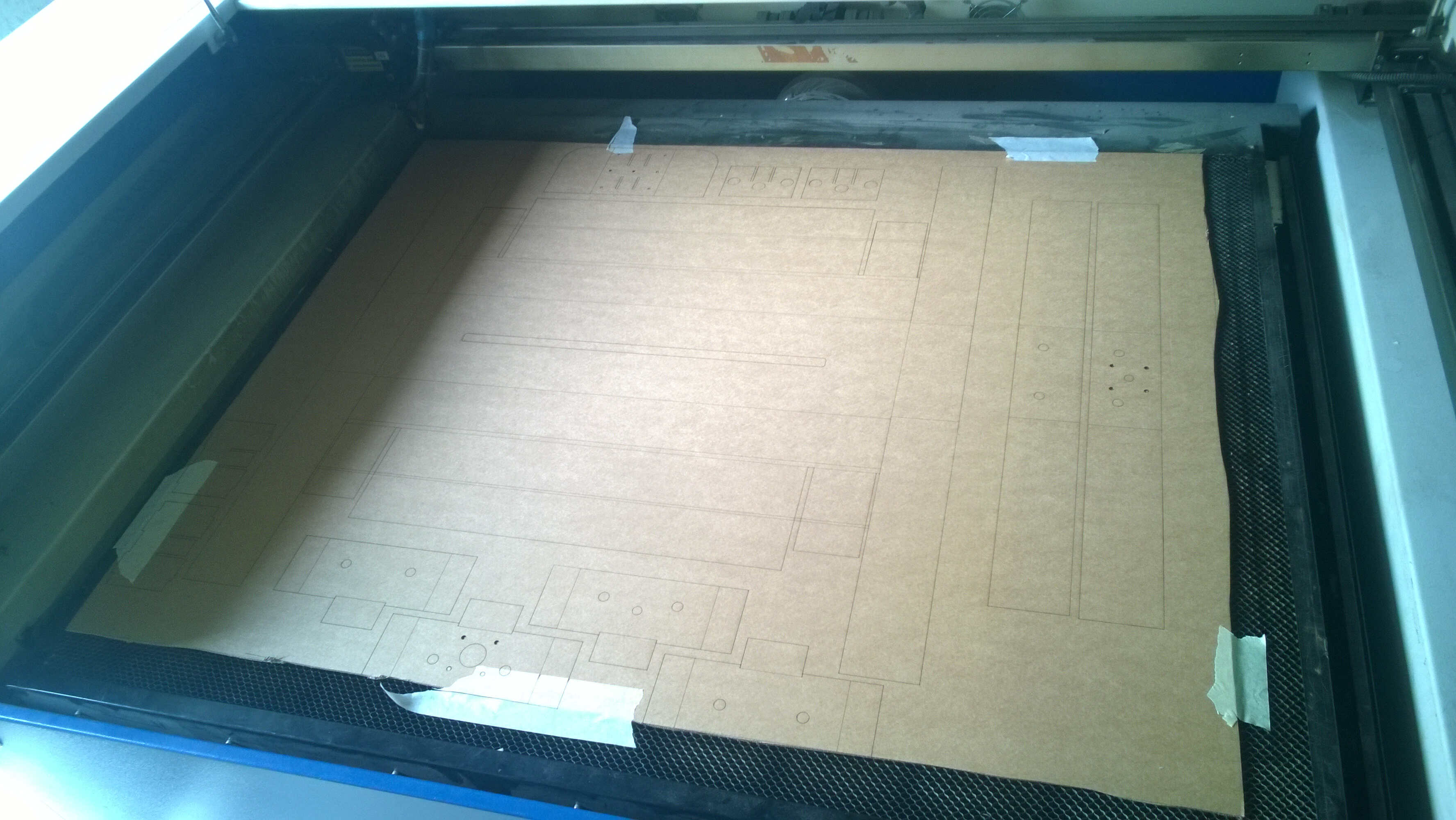
all done
- folds of the main piece didn't seem to be on the right side
- the moving part was in 2 separated parts and some cut were folds

frame extractor
main piece start of folding
moving part puzzling folding
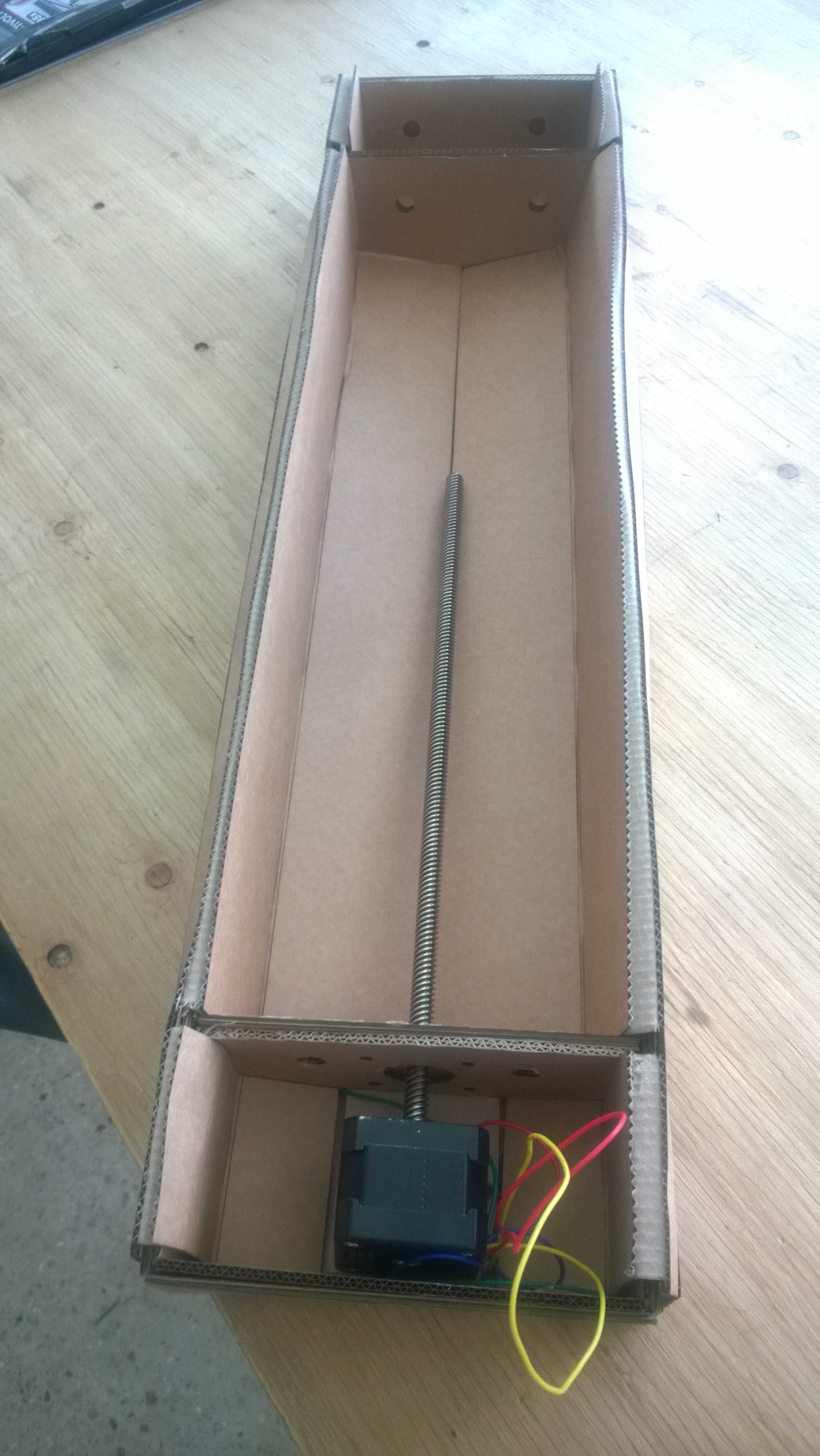
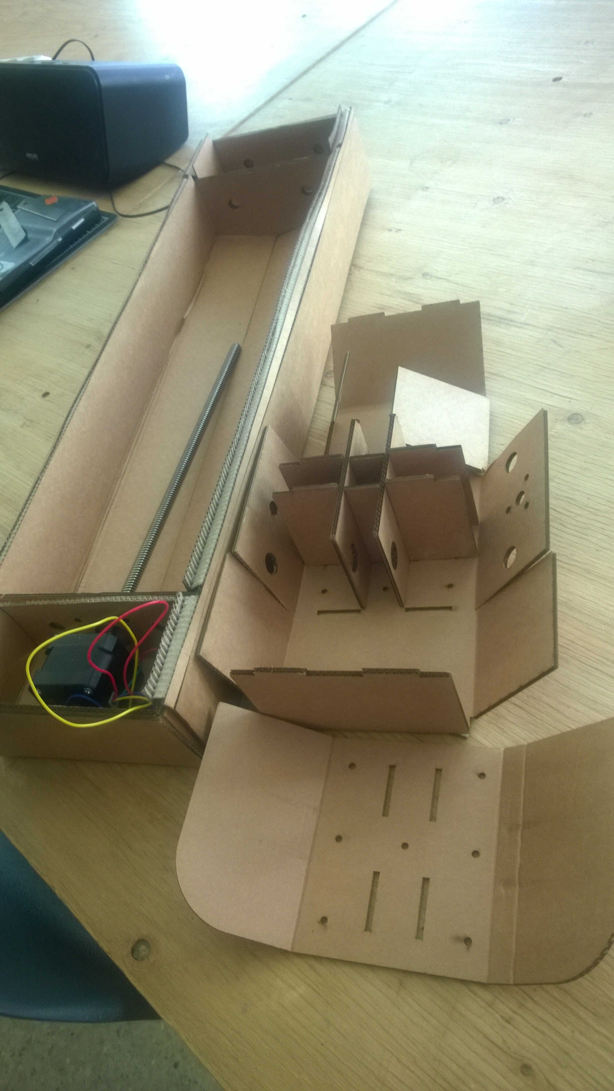
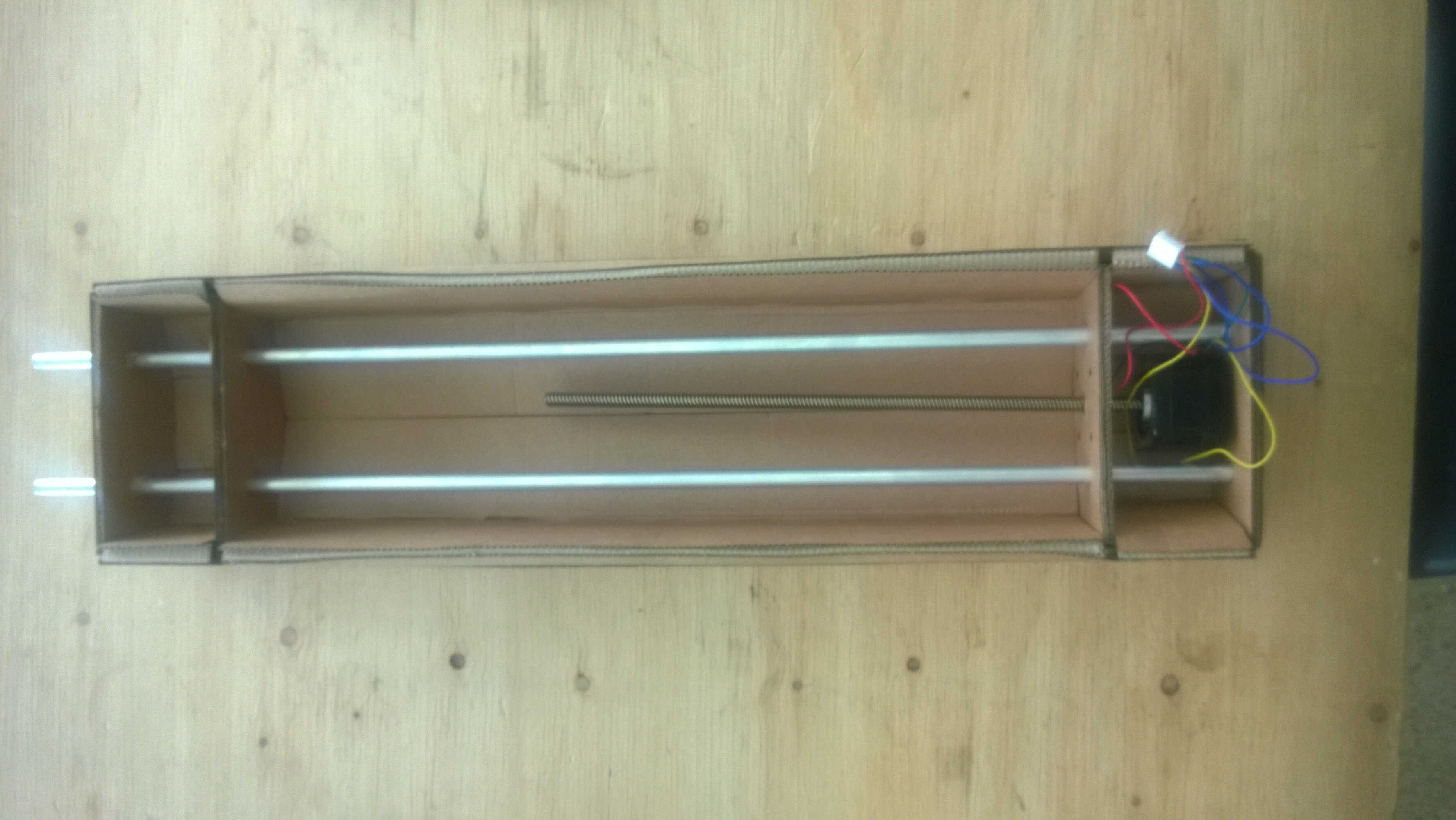
To check that I was using the good files I loaded the dxf provided on the MTM page. There is a gap between the gif/the flat view and the dxf. I assembled the tower, noticed some defaults:
- The rods are too long -the Amsterdam team replaced them with wood rods
- The cardboard is a bit too thick
- Some folds are not on the good side - I forced them to go the other way
- My external part wasn't lasered to let the rods in - I corrected with a cutter
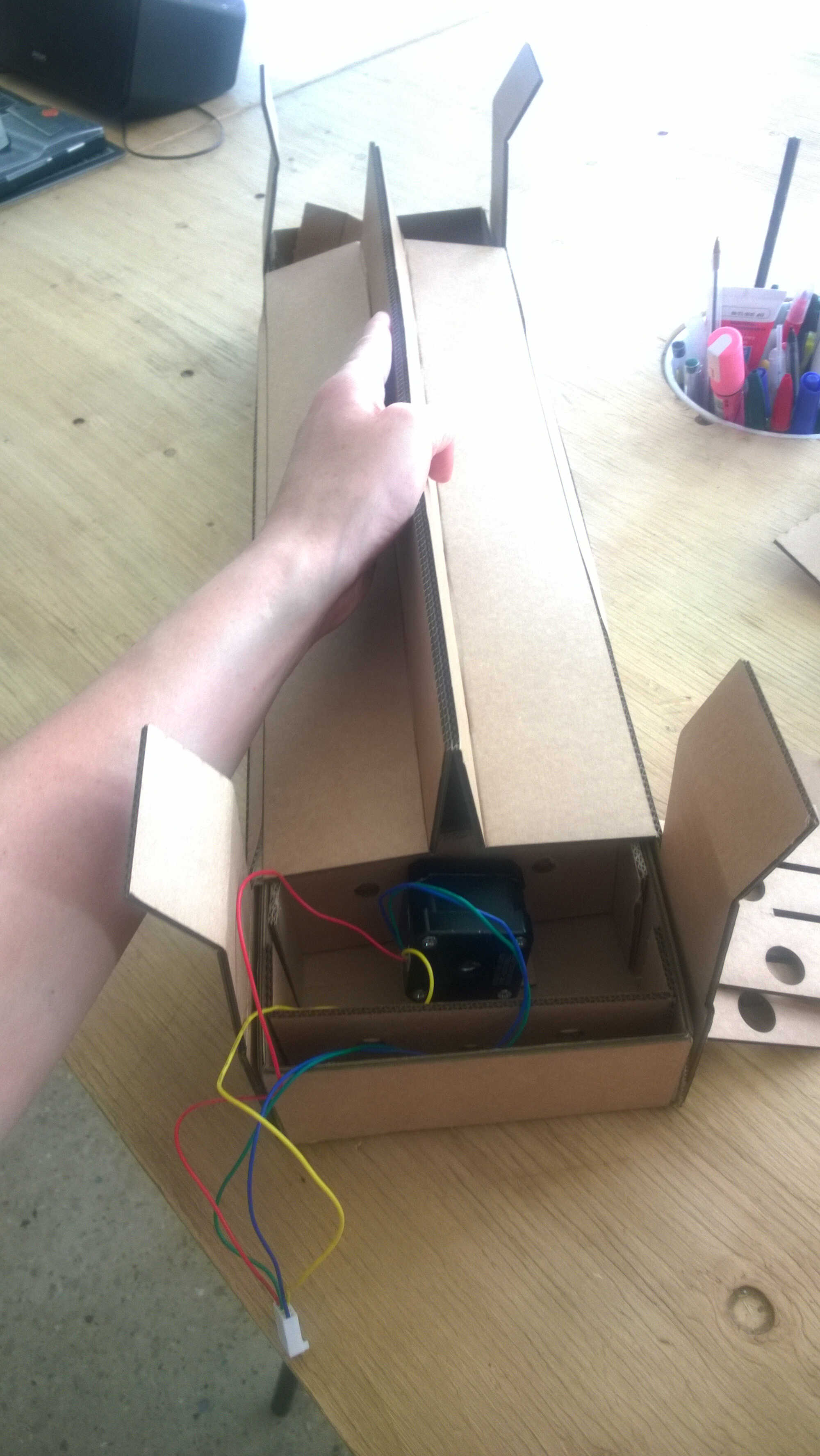
- The motor isn't wedged, at least as long as the moving part isn't added
- I couldn't assemble the moving part- I tried to "fix" it by converting with a cutter folds to cuts
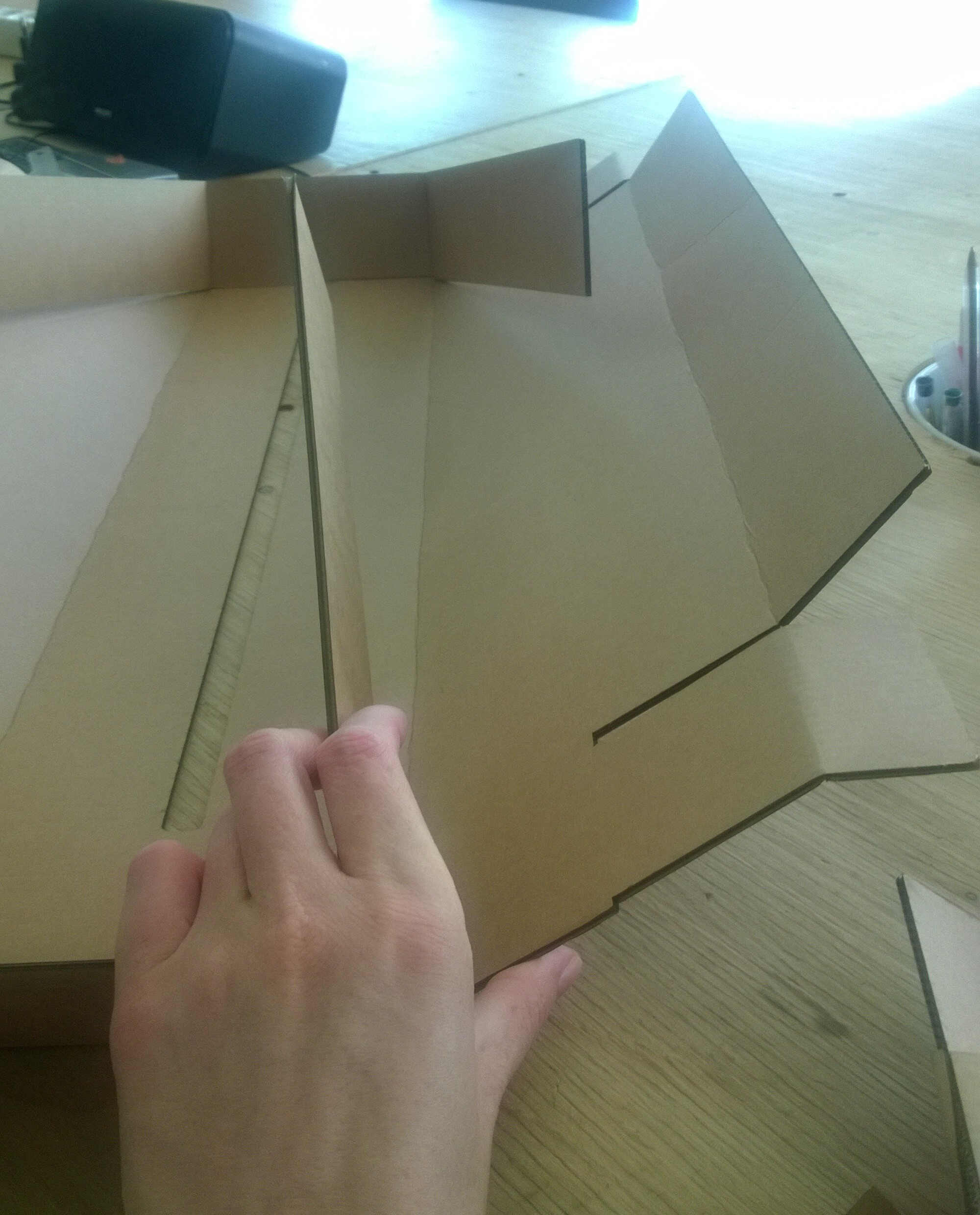
other side
folding
folded
cutter fix
all pieces
long rods
My conclusion is that this cardboard design needs to be modified in several places to be adapted to the projects. That's what the Parisian team did last year by designing a box in medium. I designed a structure with 3D printed parts at the start of this project, I think that might be a better idea. All the more so both system might require extra-structure (often in wood) to reduce the degrees of liberty.
We tried to combine all our pieces. Several mistakes made the reunion not work:
- Yassine's module didn't communicated with mine smoothly as he build a structure with a high slope
- The weight of the marbles wasn't enough to activate the stepper descent maybe with the help of rubber band or ballast it could work
- My main piece has a major default, it keep the marbles next to the main axis in a vertical descent but it won't allow a coiled ascent.
At this stage we also tested the synchronization and our ability to work together. It turned out weak and I tried to decipher why.
Taking the blame
The feeling I had during the group review was intense shame. Few groups showed machines that incomplete. I think this is the result of the failure of many actors. Once the shock passed, I suggested to Yassine to keep working on it together in order to learn what this assignement should have tought us. This being learning how to control motors precisely. He agreed.
Innovation management
I had a management training in week 17 and I had the chance to submit a practice case. I chose the group project fiasco. I explained the FabAcademy organization and some facts about the unfolding of the project. The goal was to use Berne circles, illustrating hierarchy along with Karpman's triangle. The participants diagnostic was the following:
- The leadership was problematic as no one had it and no supervisor/referee could/wanted to intervene.
- We entered a Karpman triangle, Yassine as the victim (a lot of work partially ruined), Alexis as the persecutor (last minut work) and myself as the saviour. None of those situation should last. There is always a leader in a project even in horizontal ones but the leader works as part of the team. We should consider the leader to be the assesment criteria. The problem is those criteria are relatively vague:
Shown how your team planned and executed the project
Described problems and how the team solved them
Listed future development opportunities for this project
Included your design files, 1 min video (1920x1080 HTML5 MP4) + slide (1920x1080 PNG)
There is no mention to controlling motor simultaneously for example. To go forward we would need a non-ambiguous interpretation of those assesment criteria. Then we probably still need an effective leader. This topic should be discussed openly. As tension are likely to arise we should discuss focused on facts to detach problems from people.
New start
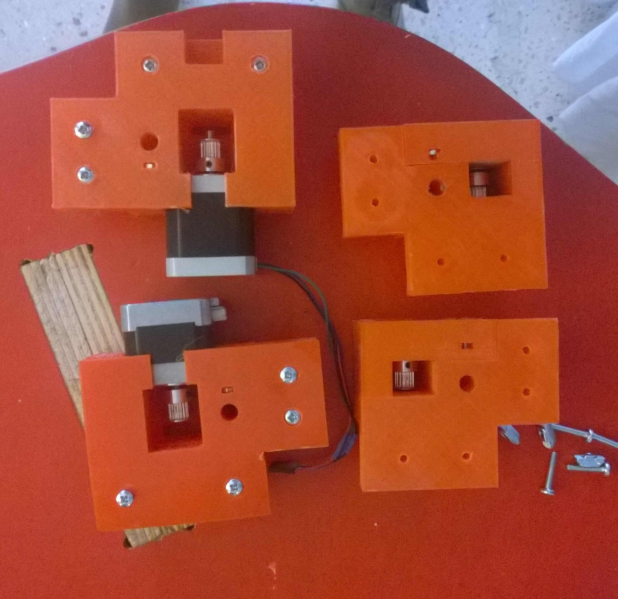
I decided to restart the project, putting the marble machine on the side. In the Amsterdam project presentation I grasped that there are 3 ways to control the motors. One being with an Arduino and a motor shield, another being with the gestalt. At that point I didn't really get the pros and the cons of each technique. I thought they were equivalent. I did the inventory of the lab, found motor shields and Arduino Mega. On the motor shield is written that it can control 2 servos + 2 stepers + 4 DC. This would hence be enough to control our machine.
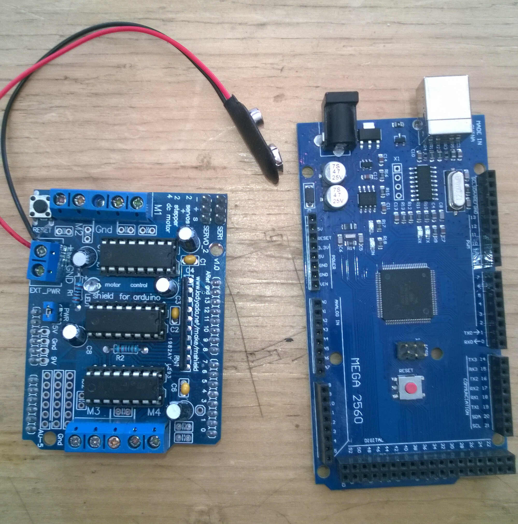
motor shield and Arduino Mega
I nevertheless decided to learn how to control a motor with a gestalt, as this was the material at disposal and I don't like wasting ressources. I didn't imagine the trouble I would face. Very few groups use gestalts, I figured out why.
My tactic plan was the following:
1. Building the Fabnet
2. Installing Pygestalt and Pyserial
3. Getting familiar with Pygestalt
4. Installing Wxgestalt
5. Testing it
Fabnet
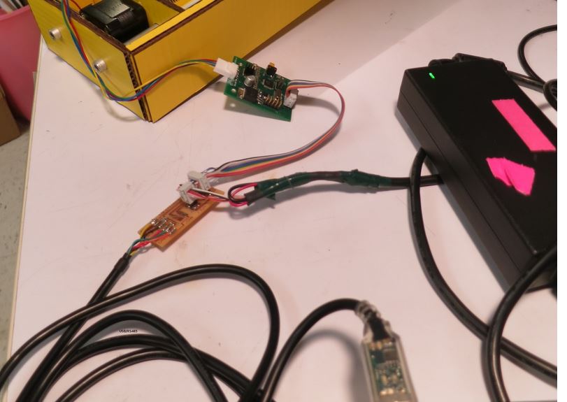
I milled and soldered Bas Fabnet with the FTDI cable provided with the machine kit. I realized later that this wasn't the best version of it and that it made the wiring and the powering trickier.
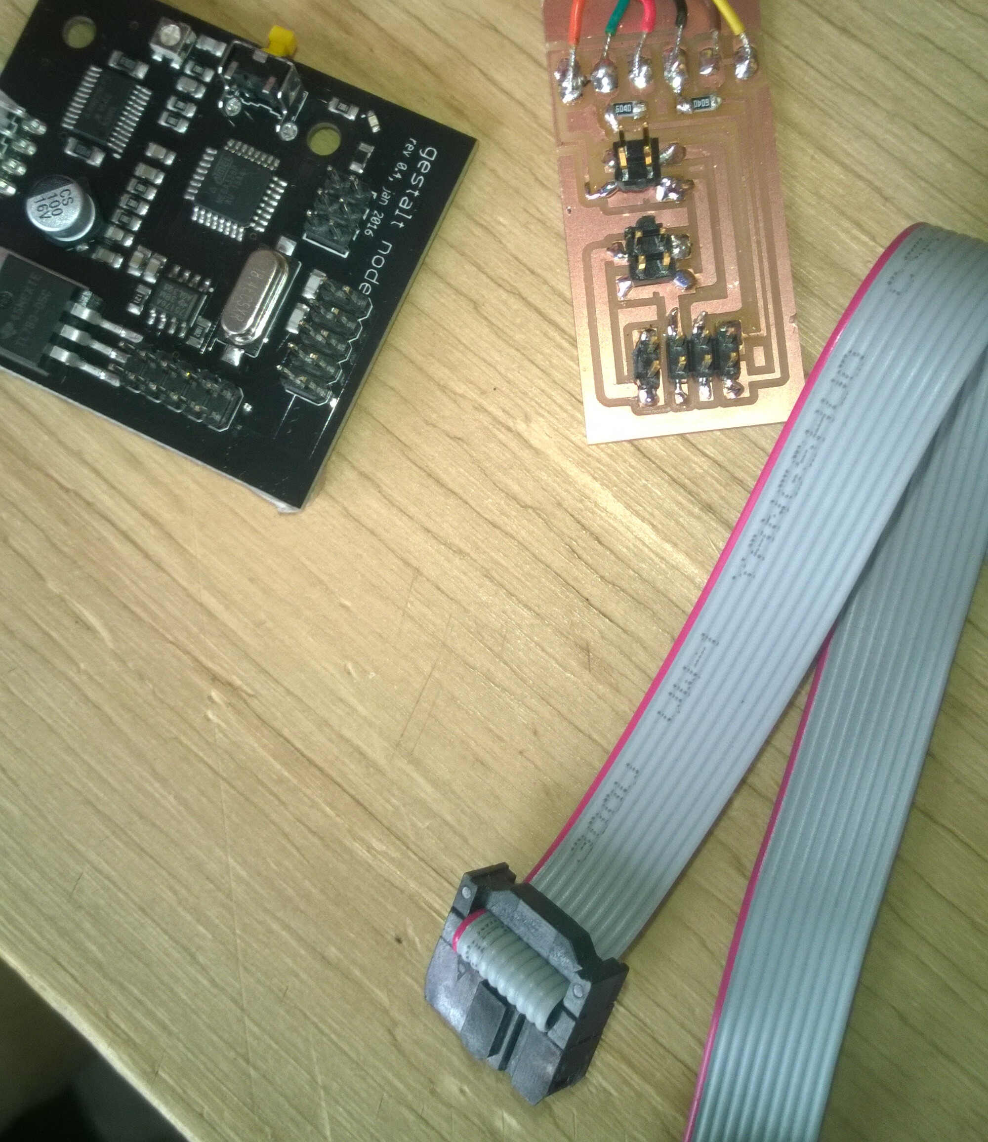
Gestalt kit ready to go
FabNet connections
gestalt node connection
The connection at the top of the gestalt is there to link Fabnet to the master node and the connection on the right side is there to connect to slave nodes. That why I used the upper one. For the final use of the Fabnet-gestalt-motor chain proper wires will be soldered to gain in clarity. I used the low power connections on the FabNet to power it with a 9V battery. This is enough to power and communicate the gestalt. For the FDTI conection to work properly I had to make a change in the single_node code (pygestalt-master>examples>machines>htmaa). I replaced portName = '/dev/ttyUSB0' with portName = 'COM3'. Without this change when running single_node.py you don't get "FABNET: PORT 3 connected succesfully "
port new name: COM3
Once I figured out how the fabnet should be wired to the gestalt I had the delight to see it blinking when executing single_node.py:
But the run ended with an error that I couldn't read as it unrolled quickly closing the window at the end. At the start of the execution was output "X axis: please identify me to the network ". I tried to find the code related to this output. I looked at the called functions: nodes, interfaces, fabnet...in vain.
called functions
I ran single_node.py it again recording the outputs with my phone so I could read the quick rolling instructions. That's how I read something about pressing the gestalt button. I reran the code and pressed the button when it was blinking. By doing so the motor got activated but it was struggling as the power was not enough. The next step is to find and connect a 12V power source.
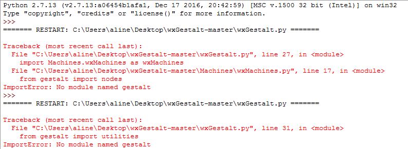
Pygestalt
To get pygestalt working it is necessary to have Python 2.7 (not Python 3!) I first tried to use the Python 3 installed along with IDLE on my computer. I could instal pyserial on it but got an error while installing pygestalt. So I rewinded and installed Python 2.7 then pyserial then pygestalt. I couldn't install with the commands I found in the documentation before I changed the environment variables. After having added Python27 to the environnement variables the command python was accepted. I could install with the command: "python setup.py install" when located in each folder (the pyserial and the pygestalt ones). I stored first stored pyserial folder in the Python27> lib> site_package and pygestalt-master folder on my desktop. In any case after being installed with the commands the are both copied in the site-packages file.
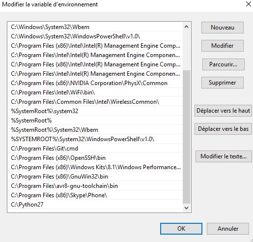
environment varibles modified
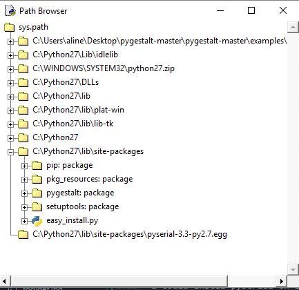
packages installed
Powering
I need 12V to move the motor. Alexis brought a transformer from his lab. It has a vintage look and a lot of wires coming out. On one connections two holes were connected together with a wire, this apparently is required for this machine to work. I asked Roman about it, he told me that by using a red and a black wire from any of the wires I should get 12V. I did as he said but obtained a 5V and couldn't even execute single_node.py. Indeed on the casing it seemed that 4 difference volatage/amperage could be obtained. Maybe by displacing the wire connecting the holes...

transformer -surrounded is the "autowiring"-
I decided to pick another option, the one chosen by the WoMa group last year, meaning connecting an old computer charger. To do so you need a female Jack connector. I couldn't find one at WoMa so I decided to buy some. I went to 2 different electronic suppliers and I bought one to each.
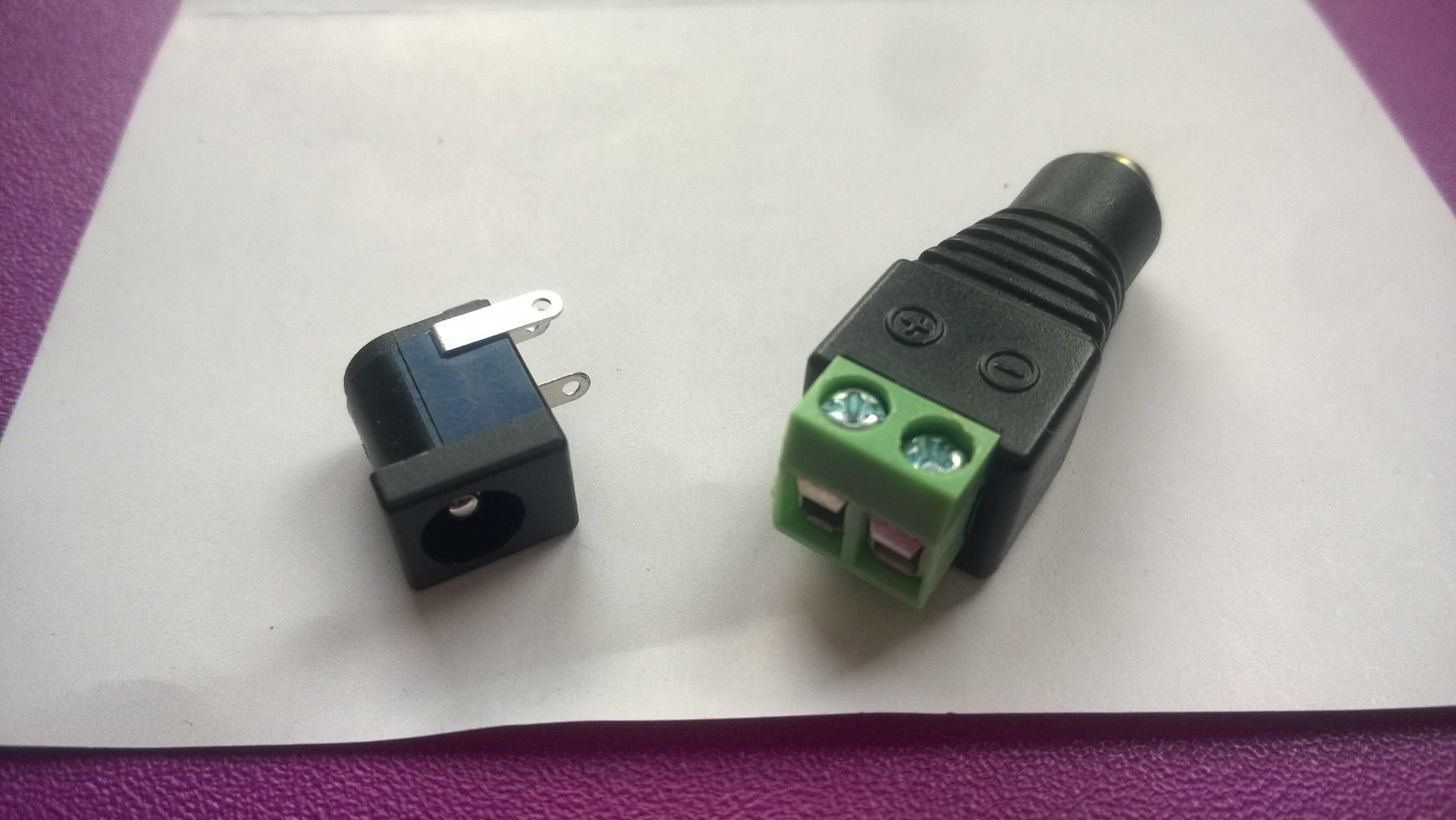
jack connectors
Now I have to wire those to the board. By browsing Nadya's page I found a picture quite interesting:
Nadya's powering
Nadya didn't use a jack connector but stripped the transformer wires instead.
Gestalt understanding
After installing everything I discussed gestalt with Roman and he told the big adantage they have on other sytems. With them you can input a distance and the gestalt will figure out the best way to reach it. They are of particular interest for Drawbots for examples, with them you don't have to look for coordonates sytem changing algorithms. Well now I am not quite sure this is the best option for us as we probably would like to make the move conditionate to an event (end stop interruptor for example). Gestalt cannot deal with other type of input, an Arduino/Satchakit would be needed. Based on those facts a satchakit + a motor shield would seem the relevant option. But before starting everything anew let's look at the gestalt libraries. To know more it is possible to read this thesis. It would be helpful to have a simple tree structure explaining in a sentence the purpose of each function.
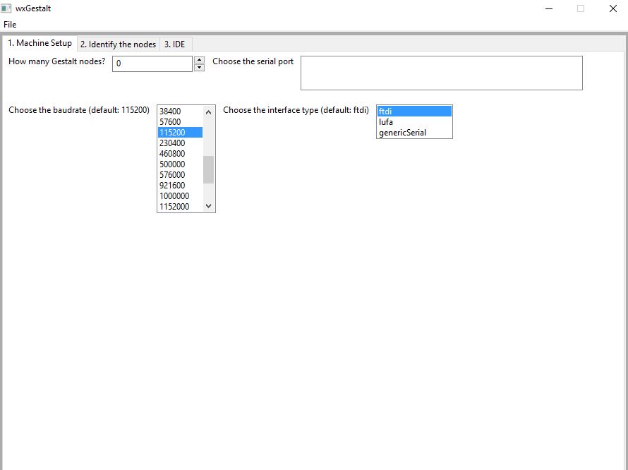
Wxgestalt
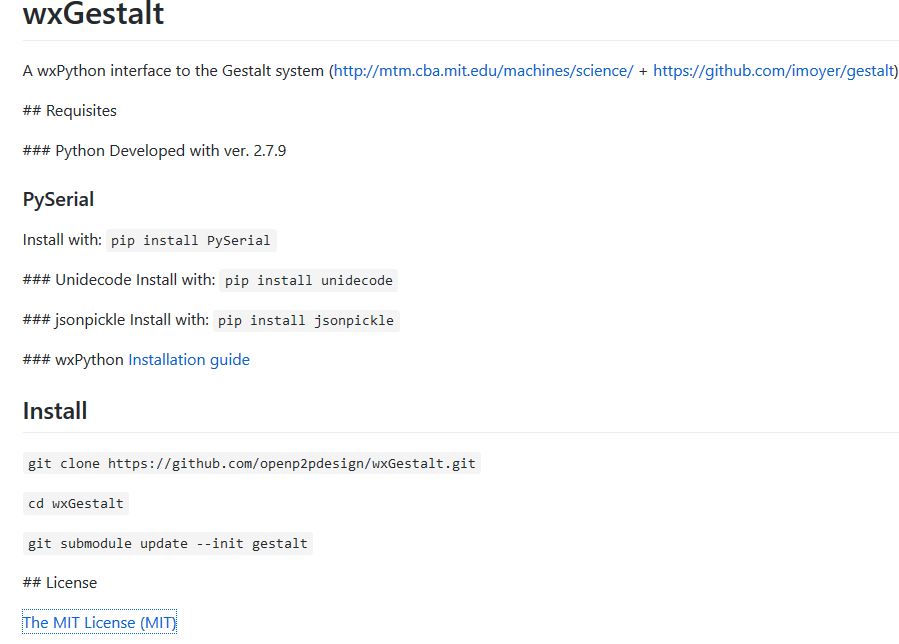
I supposed it would be easier to pilot the motor with an interface. So I tried to install Wxgestalt. I started doing as I did for pyserial and pygestalt, by copying the whole file but there is no setup function in this one. You need to use the commands: "git clone https://github.com/openp2pdesign/wxGestalt.git" then "cd wxGestalt" and "git submodule update --init gestalt" The only thing is that after the git clone command Git will ask your identifier and password for Github. I forgot them....
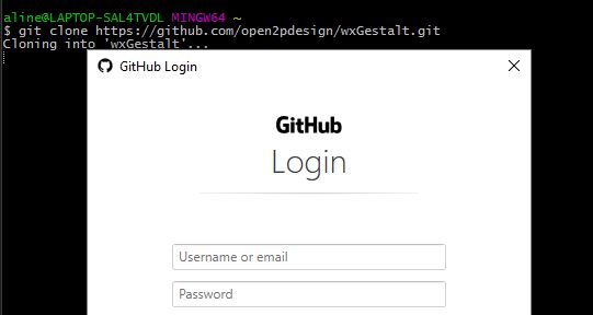
Github connexion
Then I reinitialized my account and started again.
command install
WxGestalt was installed in my user folder. The whole gestalt library is inside of it but not with the modified single_node.py, it is the initial one. I am not confident about the fact that I have several gestalt folders. And now I have no clue what to do next. The instructions are quite undetailed. GitHub is the only place where to find the function of each folder.
instructions
Based on this I assume that the ## are requisited, then what about the triple ones? Are they optional? Are they inside Python 2.7? How can I open this interface or input the license file? I tried to run wxGestalt.py the function in the main folder. When doing so I had an error: "Traceback (most recent call last): File "C:\Users\aline\wxGestalt\wxGestalt.py", line 5, in
wx installation
Then I relaunched Wxgestalt.py but got another error: "Traceback (most recent call last): File "C:\Users\aline\wxGestalt\wxGestalt.py", line 5, in
wx version change
I relaunched again, this time with unidecode error. So the triple # are also requisited. So I installed unidecode and jsonpickle. The command pip was not found in the wxgestalt folder. So I used the commands: git clone https://www.tablix.org/~avian/git/unidecode.git > cd unidecode > python setup.py install
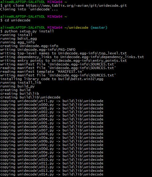
unidecode install
As for jsonpickle I didn't find a place to clone it from so I downloaded the gz.tar files, extracted it with 7zip, went to its folder and installed it.
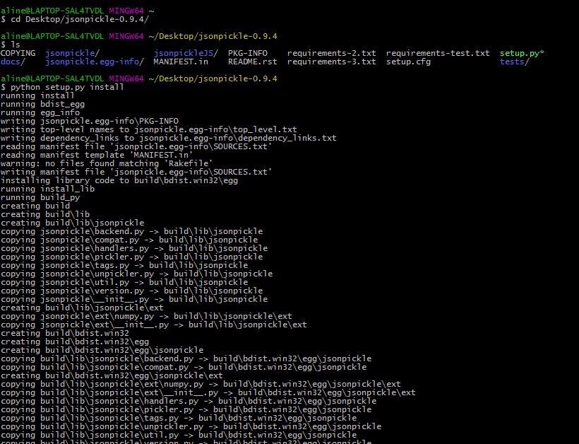
jsonpickle install
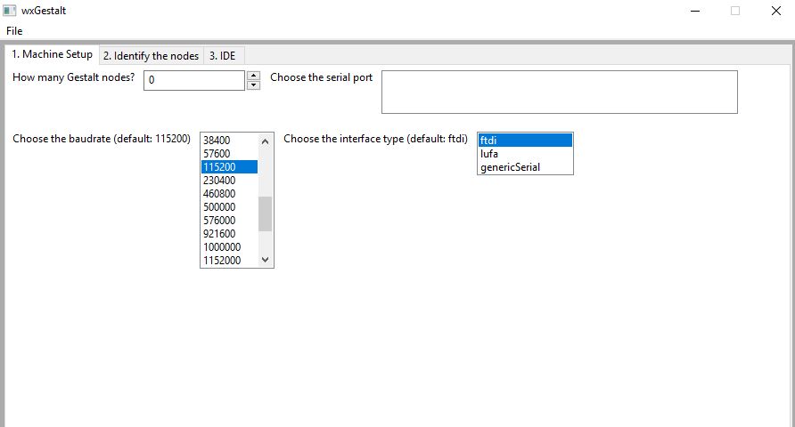
Then I relaunched wxGestalt and, tadaaam, it finally worked:
interface
Now i get the ###, my Python version was 2.7.13 and not 2.7.9 as requested. I found this info in IDLE. That is why I had to install wx, jsonpickle and unidecode. This was quite a complicated process.
One node initialization
While struggling with my inputs, I tried to make some progress on the group project. As I had a new jack connector I was able to plug it on my board and use an old laptop baterry to power my motor with 12V 2A current. With such a power I was able to correctly calibrate my motor with single_node.py. This function positions the motor in 4 places and generated a .vdm file. When a .vdm is generated it is not possible to rerun signle_node.py unless the generated files are deleted. At that point I was a bit stuck as the official documentation doesn't explain what to do next.
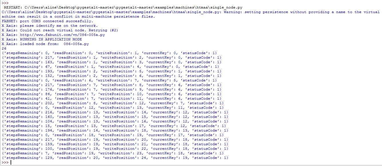
positioning
The video shows the run of single_node:
Wxgestalt
I installed Wxgestalt to interact easily with the motors and the gestalt library. First I had to replace gestalt by pygestalt.
Wxgestalt interface
Error
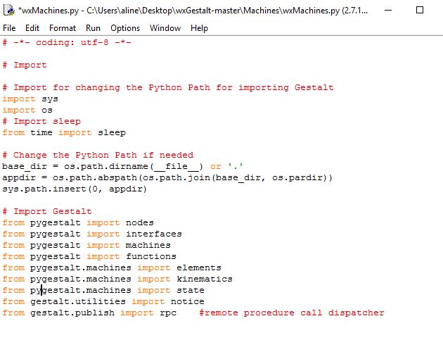
Gestalt > Pygestalt
But I couldn't use it because of many exceptions.
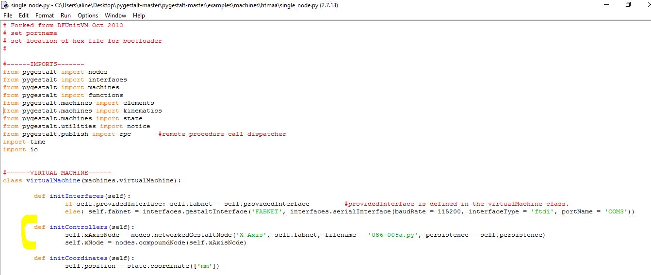
Gestalt with 2 motors
As we had 2 motors in the marble project I wanted to be able to synchronize 2 motors. Last time I was able to initialize one motor with the single node piece of code. I looked at James MTM documentation for indications. He explains how to complement the single node code for 2 motors. Based on this I wrote this initialization sketch:
  #------IMPORTS-------
  from pygestalt import nodes
  from pygestalt import interfaces
  from pygestalt import machines
  from pygestalt import functions
  from pygestalt.machines import elements
  from pygestalt.machines import kinematics
  from pygestalt.machines import state
  from pygestalt.utilities import notice
  from pygestalt.publish import rpc	#remote procedure call dispatcher
  import time
  import io


  #------VIRTUAL MACHINE------
  class virtualMachine(machines.virtualMachine):

    def initInterfaces(self):
      if self.providedInterface: self.fabnet = self.providedInterface		#providedInterface is defined in the virtualMachine class.
      else: self.fabnet = interfaces.gestaltInterface('FABNET', interfaces.serialInterface(baudRate = 115200, interfaceType = 'ftdi', portName = 'COM3'))

    def initControllers(self):
      self.xAxisNode = nodes.networkedGestaltNode('X Axis', self.fabnet, filename = '086-005a.py', persistence = self.persistence)
      self.yAxisNode = nodes.networkedGestaltNode('Y Axis', self.fabnet, filename = '086-005a.py', persistence = self.persistence)
      self.xyNode = nodes.compoundNode(self.xAxisNode, self.yAxisNode)

    def initCoordinates(self):
      self.position = state.coordinate(['mm', 'mm'])

    def initKinematics(self):
      self.xAxis = elements.elementChain.forward([elements.microstep.forward(4), elements.stepper.forward(1.8), elements.leadscrew.forward(6.096), elements.invert.forward(True)])
      self.yAxis = elements.elementChain.forward([elements.microstep.forward(4), elements.stepper.forward(1.8), elements.leadscrew.forward(6.096), elements.invert.forward(False)])
      self.stageKinematics = kinematics.direct(2)	#direct drive on all axes

    def initFunctions(self):
      self.move = functions.move(virtualMachine = self, virtualNode = self.xyNode, axes = [self.xAxis, self.yAxis], kinematics = self.stageKinematics, machinePosition = self.position,planner = 'null')
      self.jog = functions.jog(self.move)	#an incremental wrapper for the move function
      pass

    def initLast(self):
  #		self.machineControl.setMotorCurrents(aCurrent = 0.8, bCurrent = 0.8, cCurrent = 0.8)
  #		self.xyzNode.setVelocityRequest(0)	#clear velocity on nodes. Eventually this will be put in the motion planner on initialization to match state.
      pass

    def publish(self):
  #		self.publisher.addNodes(self.machineControl)
      pass

    def getPosition(self):
      return {'position':self.position.future()}

    def setPosition(self, position  = [None, None]):
      self.position.future.set(position)

    def setSpindleSpeed(self, speedFraction):
  #		self.machineControl.pwmRequest(speedFraction)
      pass

  #------IF RUN DIRECTLY FROM TERMINAL------
  if __name__ == '__main__':
    stage = virtualMachine(persistenceFile = "test.vmp")
    #stage.xNode.loadProgram('../../../086-005/086-005a.hex')
    #stage.xNode.setMotorCurrent(1)

    stage.xyNode.setVelocityRequest(8)
    #f = open('path.csv','r')
    #supercoords = []
    #for line in f.readlines():
    #	supernum = float(line)
    #	supercoords.append([supernum])

    supercoords = [[10,10],[20,20],[10,10],[0,0]]

    for coords in supercoords:
      stage.move(coords, 0, 2)
      status = stage.xAxisNode.spinStatusRequest()
      while status['stepsRemaining'] > 0:
        time.sleep(0.001)
        status = stage.xAxisNode.spinStatusRequest()
This is practically the same sketch as xy_plotter.py but xy_plotter causes an error when run. To understand this piece of code I found useful ressources.
First the official gestalt info I didn't found so far.
Then this useful pdf on how to switch to 3 axes.
Here the video:
I tried to initialize with wxgestalt but errors keep happening such as "Node doesn't have requested attribute".
So I now can displace several motors at indicated coordinates. What's left to do is to defined the path in term of coordinates and speed (with initKinematics and setSpindleSpeed functions for example) I know some use Rhino to do this, some others StippleGen.
Bridging Arduino/Gestalt
In order to control end effector not reliable on motors gestalt can't be used. The easier being to link it to an Arduino-like board the Parisian group did last year. I found some pages bridging Arduino and gestalt such as Caputo's or Thomas's.
Here a nice example of Gestalt node made in the Fablab.
Here a nice Python coding example, for a tripod.
Here a nice example of how to convert a drawing into coordinates
Here a project where they replaced gestalt by Marlin a firmware for RepRap based on Arduino.