
Machine Design
Assignments Goals
- Automate your machine. Document the group project and your individual contribution.
Week's Lectures


Preface


This week's assignment was very hard to start with, because even following the instructions on the [m]MTM site, and the FabAcademy Tutorials, I found that it's really confusing and there's a lot of documentation missing or outdated: for example the Gestalt Nodes board we received are rev 0.4 but there's no history log about what's different from the rev 0.3; the main page of pyGestalt states that the Gestalt will be available as an open source library in November 2013. So check back!, but we're in 2016!!
The most comprehensive documentation I found is Ilan's Master Thesis. It's a well written dissertation on the Gestalt Framework, and after reading all of the 153 pages I cleared a lot of confusion I had in my mind, but despite it's a wonderful theoretical document it lacks practical code examples. The last section covers several examples of really interesting machines, but without a line of code examples!!
Moreover according to me it's not clear what's the general workflow needed to build the entire system, starting from scratch. So after a lot of studying and peeking at the work and sites of previous years students, we managed to get everything almost working.
So in this page I'm going to try to explain in detail what is the workflow one should follow to get Gestalt Modules up and running in the most clear way possible, because something even super-powerful it's useless if not well documented...
FabNet
The physical communication layer used between Gestalt nodes is based on a serial protocol called RS-485. The main characteristic of RS-485 is that it uses a differential balanced line over twisted pair, so that can span relatively large distances, to create a communication bus protected from eletrical interference.
Since comsumer PC don't have a RS-485 port (and most of nowdays notebooks lack the RS-232 serial port too) we'll need a converter to communicate on the bus: USB to RS485 Serial Converter Cable.

The original Fabnet Adapter uses a 2x4 connector (hence not a straight through ribbon cable), and if you look at the schematic of the Gestalt Module, you can see that it uses only the 12V signal, so there's no use at all for the 'LOW VOLTAGE' connector on the adapter!
There's an alternative version of the adapter by Bas, but it's impossible to find its Eagle schematic and board, so I decided to create my own version of it, with full Eagle schematic and board.
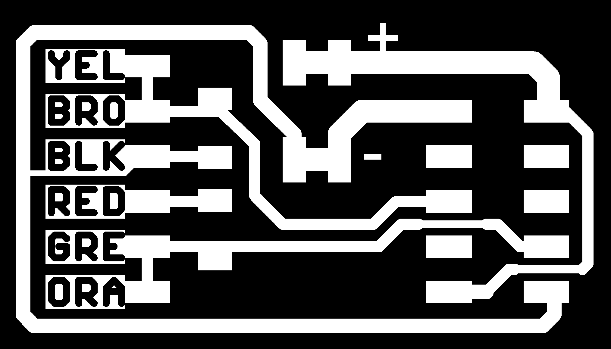

In it I added a quick block release connector for the 12V/GND signals, a master switch for Power ON/OFF and a led to notify the power state.


Work files links

GF_FabnetAdapter.zip
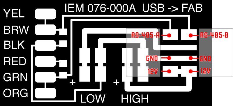
Electrical wiring
The Fabnet provide access to the physical layer of communication. So every Gestalt module on the system is daisy chained to the next one, as if they actually were network nodes.
The whole wiring diagram is then the following:

At the beginning we attached the arduino with the servo motor directly to the PC, using a second serial port. But because this solution seemed too bulky and cumbersome, we explored further and managed to connect everything on the FabNet, using an Arduino with a custom made shield, to provide RS485 connectiviy, as all the other Gestalt Nodes. More info about it below.
Installing the pyGestalt Framework
The Gestalt framework is an extensible collection of Python software modules that can be combined in many ways to quickly realize machine controllers.
In order to use the Gestalt Framework, Python is required. I used version 2.7.11. Once Python is installed on the system (and the PATH should has automatically been set), it's time to install the Gestalt Framework (called from now on pyGestalt).
Download the latest version from Nadya Peek's github repository, open the local directory and execute the following command from the prompt:
python setup.py install
That way, you should have all the classes and interfaces installed in the Python system folders.
Virtual Machine Architecture
The approach adopted by Gestalt is that of a virtual machine controlling a real machine. The virtual machine is a computer-based representation of the physical machine that often times will run on the user’s computer, that describes how the real machine should work, kinematic definitions, memory of state (i.e. position), machine-level functions (e.g. to move the machine) and external interfaces through which user applications can control the machine.


The virtual machine is interfaced to the real physical nodes by means of virtual nodes, that specifies several interface functions to control the hardware part of the machine.
In our case, the hardware components of the machine are the lead screw motors and the servo and the physical control node is the Gestalt Nodes received in the kit. The virtual nodes are the Python scripts associated with the Gestalt Nodes, called 086-005a.py.
Another important aspect of the architecture is the definition on different types of Nodes:
- solo/independent nodes
- solo/gestald nodes
- networked/gestalt nodes
For a more detailed and comprehensive explanation of them, I recommend to read Ilan's thesis, from page 35.
In our machine, the PluriBot, all the nodes used are Networked/Gestalt Nodes, even the servo motor, thanks to the Arduino custom shield.
Virtual Machine Definition and Folders Structure
Since the folder structures in both Nadya's repo and Imoyer's repo are quite messed up, and there's little structuring on folders meaning and relations between them, I decided to re-organize all the needed files and folders in a more logic way, so that should be easy enough to understand how to add a new interface, node or virtual machine in it.

- firmware:
embedded gestalt library, for gestaltNodes with ATMega328p or Arduino Nodes - GF_FabNetAdapter:
schematic and board layout for modified version of Fabnet Adapter - nodes:
everything related to virtual and physical nodes of the virtual machine- arduinoServo
contains Arduino sketch, python interface, schematic and board layout for the custom shield , with RS485 transceiver
Readme!!.txt contains warnings about symbolic links - gestaltNode
contains embedded software, python interface, schematic and board layout for the gestaltNode rev_0.3
- arduinoServo
- virtual machine:
machine definition, Rhino and Grasshopper files to design path movement parametrically
At the beginning we wanted to create a virtual machine consisting of a compund X/Y node for the plane movement and two separte nodes, one for the servo motor and one for the syringe plunger, starting from the xy_plotter.py included in the Example Folder of pyGestalt. But after doing a lot of tries and reverse engineering of the examples, I couldn't get a correct virtual machine morking. So I created a X/Y/Syringe compund node and a separate servo node.


The reason why I wanted a separate X/Y compund node is because the different function of each node and the timings governing the movements: X/Y plane has to be synchronous, but the servo and the plunger have to move only after the needle is in the right X/Y coordinates. Morover, the syringe plunger has to move only after the servo has pushed the needle down.
To overcome the problem of synchronicity with X/Y/Z nodes and use the full compound node, I had to generate some fake coordinates in which the Z position is always the same, then keep X/Y the same and change only Z position and so on. For example:
moves = [
[20,80, 0],     # Move actuator in position (20, 80), and keep Z still
[20,80, 10],    # In the same X/Y position as before, keep X/Y stil and moves only Z
[30,60, 10],    # Without changing Z anymore, move to new position in X/Y
[60,15, 10],    # and so on...
]
So, in the end the virtual machine for the PluriBot is that one:
One problem I noticed during the development of the virtual machine, is that ther's some kind of bug with file names for the python node interfaces: if for example the node interface file name contains '_', the resulting temp.vmp persistence file ends up corrupted.
After modifying all the filenames to overcome this bug, everything went smooth and I managed to pair every node on the FabNet, even the Arduino one with the custom shield.

Work files links
PluriBot_v1.zip
Servo networkedGestaltNode (Arduino custom shield)
To add a servo motor controlled by the virtual machine, at first we explored the solution of using an Arduino listening on the serial port for a specific character to move it down and up. That solution worked fine, but had the drawback of using an additional separate serial port to communicate with the Arduino UART.
So after a lot of reverse engineering of the gestalt.cpp and gestalt.h files and the Arduino basicNode example (almost useless...), and exploring in every folder of Ilan's and Nadya repos, I managed to create a custom shield for an Arduino that provides RS485 connectivity and pairing procedure on the FabNet.


The source code is quite simple and self explainatory, but some small modification to gestalt.cpp and gestalt.h needed to be done in order to use the bus at 115200 and add the precompiler #define networkedGestalt (Arduino IDE doesn't allow to define some project-wide #define!!)
The last missing piece to put everything together is the python interface, that links the virtual machine to the physical shield node. In this file I defined the two functions that "talk" to the relative functions inside the Arduino code: needleUp and needleDown.
Grasshopper Interface to generate toolpath
In order to make easy to produce awesome bubble graphics, we have decided to produce a Grasshopper scketch that will generate the array with the positions for the Pluribot Machine.
In the rhino canvas we have some circles that rapresent our wrap bubbles, by the right click of the mouse on the surface grasshopper component we must select the Set Multiple Surfaces, then we have to select the desired circles in order to draw something and press Enter when finish
Now our Output will be the array that we need.

Assignments Outcomes
- Work and communicate effectively in a team and independently
- Design, plan and build a system
- Analyse and solve technical problems
- Recognise opportunities for improvements in the design
Have you:
explained your individual contribution to this project on your own websiteshown how your team planned and executed the project
described problems and how the team solved them
listed future development opportunities for this project
included your design files, ‘hero shot’ photos of the machine and a short video of it operating