Assignment:
A_ Make the board/FabISP in-circuit programmer.
B_Stuff the board-components + soldering.
C_Program the board.
B_Stuff the board-components + soldering.
C_Program the board.
A_Make the board.
The FabIsp
A FabISP is an in-system programmer for AVR microcontrollers, and it is used to load program onto the microcontroler. Frst we need to produce the actual board, stuff it with components and finally load it with a program. Once loaded it will acquire the capacity to be used to load the program onto other Isp board.
The Usbtiny44 we are making is designed to be made in Fablabs.
I found helpful to review the different versions that are proposed in the class archive to get a better understanding of what is a FabIsp, its function and get familiar with the basic electronic components.
Building the FabTinyISP
FabISP, a fab-able in-system programmer
FabTinyStar
Download the board files.
To proceed with the exercise I refered to the tutorial on our lab page.
Electronic production tutorial
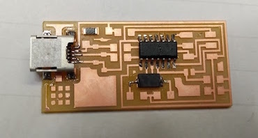
I first downloaded the png files and saved them as images. There are 4 files provided.
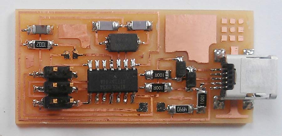
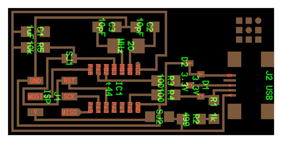
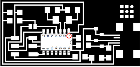
The first one is an example of the finished board. The next one is the labeled board which serves as reference for tracing and to know which components and where they have to be placed on the board.
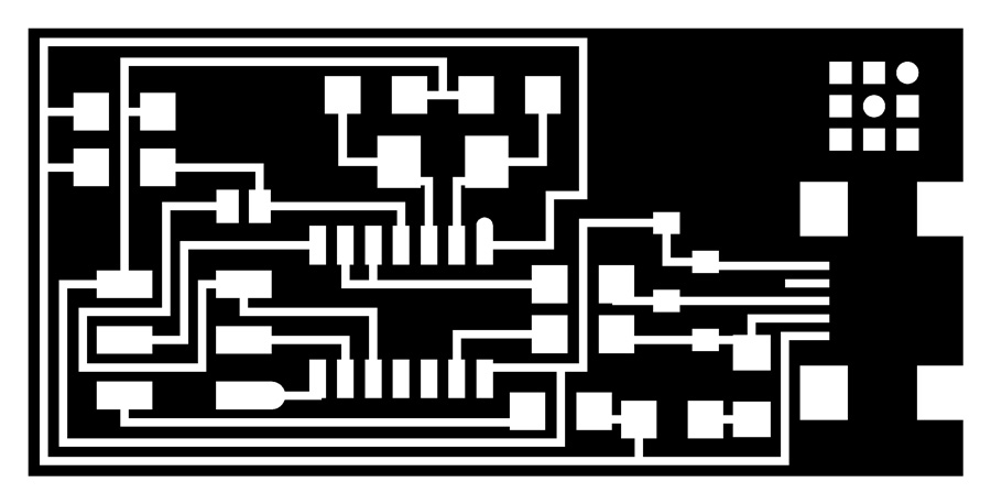
The other 2 are the files needed to mill the FabIsp. The

Milling the board.
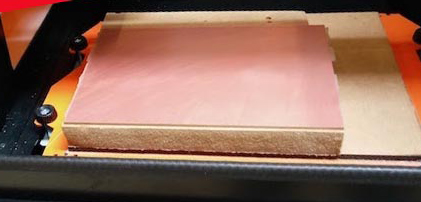
Milling a board is a delicate operation and has a minimal error tolerance. Before starting with the actual milling it is important to make shure the board is straight/flat. An easy way to do that is laying the board at a 90º angle against a metal ruler and look at it sideways against a light source. If the light spills between the board and the ruler that means it is bent and will not lay flat on the bed, and consequently the 0 of the Z axis will not be accurate on the whole surface of the board. If so straighten it until there is no gap.
Wipe all dust off the back side of the board and apply double-sided tape on the back surface of the board.(not the copper face)
Make shure the milling bed is also clean and free of any scratches, dust, etc. It is crucial that the board lays 100% flat (leveled) on the machine bed otherwise it may not mill through the copper layer on the whole surface.
Place the board perpendicular to the Y axis, and as close to the default 0 of the machine.
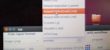
Open the application from the desktop. In this case I choose the machine protocol for the SRM20.
It is preferable to mill the circuit board trace before the outline board. The circuit board is milled using the 1/64 end mill.
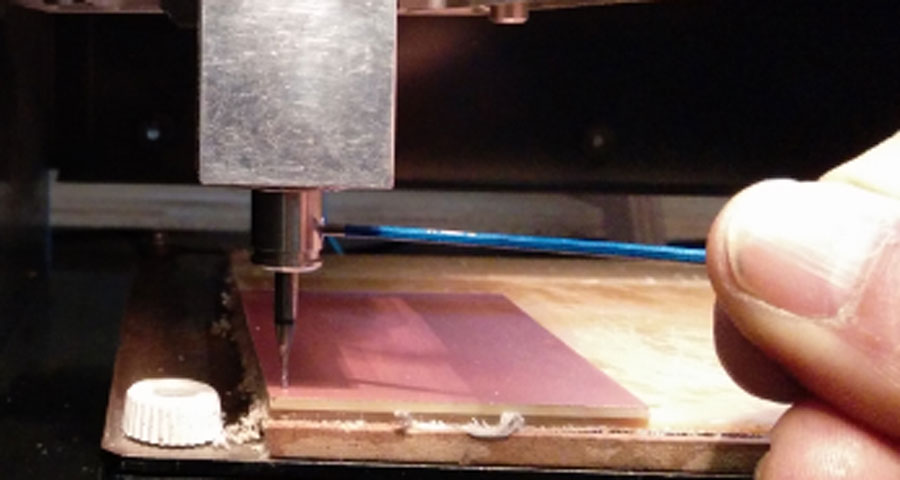
I fixed the end mill to the machine spindle - no need to tight it too strongly.
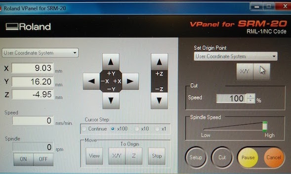
Set the 0 on the Z, X and Y axis. That consists of physically placing the tip of the end mill at the exact spot where the job should start.
Setting the Z axis: Move the spindle position using the x and Y axis button until the spindle is placed over the surface of the board and, using the Z axis botton bring the tip of the end mill at approx. 5mm. above the board
Loosen up the end mill from the head and let the end mill tip touch the board
tighten the end mill to the spindle and PRESS Z axis botton. Not forget to always comfirm the operation.
Setting the X and Y axis: Move the spindle to the corner of the board where I want the job to start leaving a few mm. offset from the edge of the board on both axis.
Again PRESS the X/Y axis botton to comfirm the 0 settings.
PRESS home. The machine will take the head back to a safe position but remembers the X,Y and Z axis.
Open the fab module.
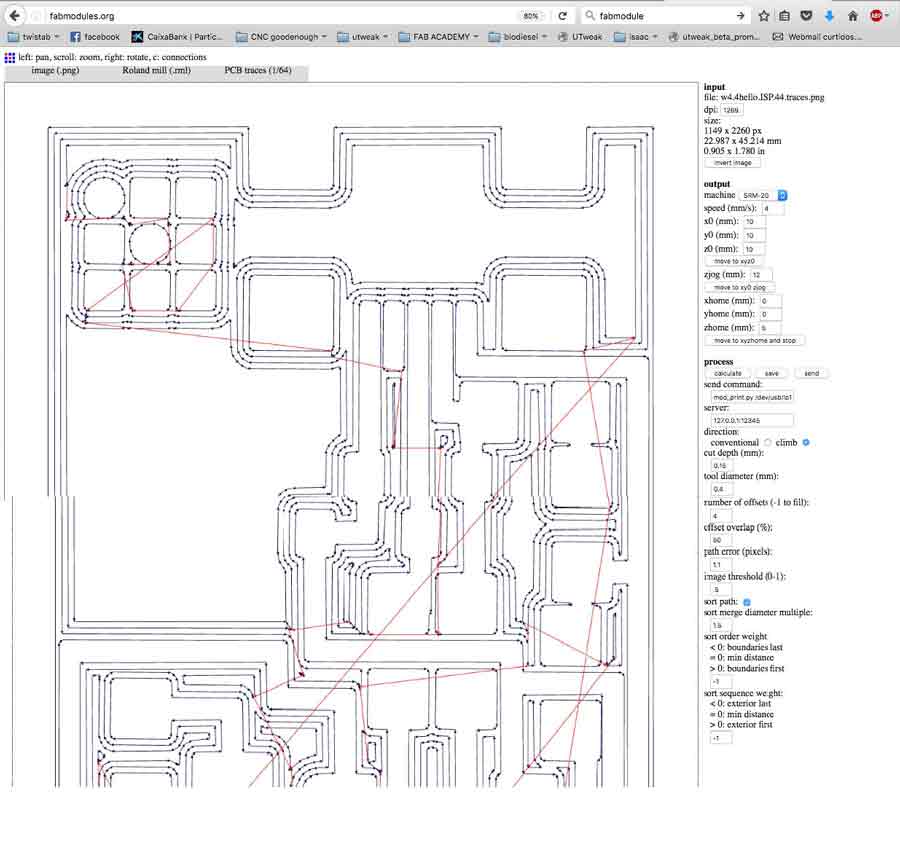
1-Open the trace png file
2-Select the milling machine SRM20.
3-Select the type of job to be done: PCB traces (1/64).
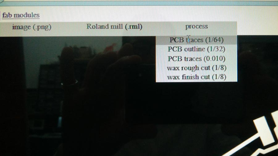
4-In the right window select the output/milling machine: SRM-20.
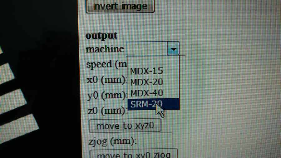
5-That sets default parameters to trace the PCB.
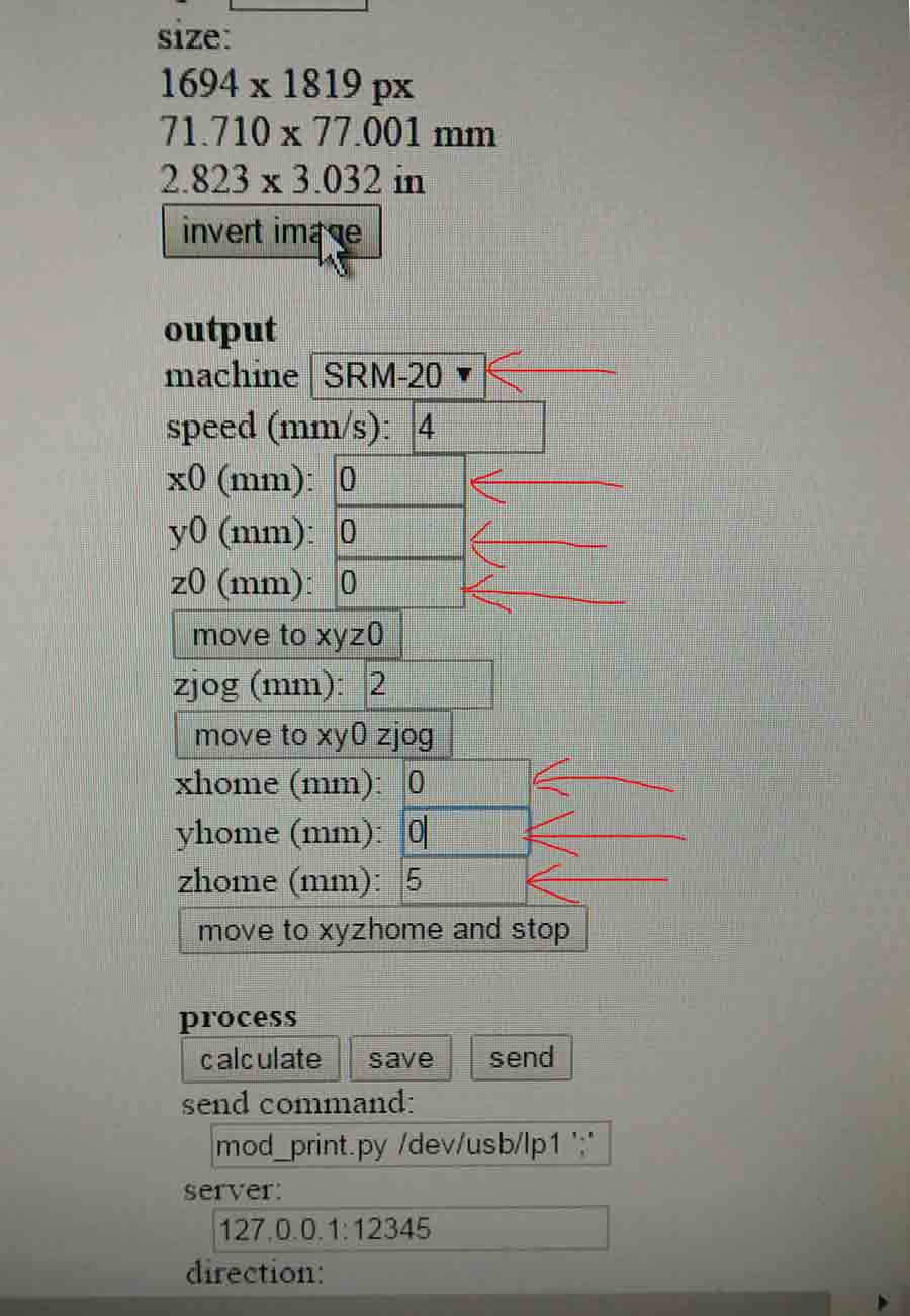
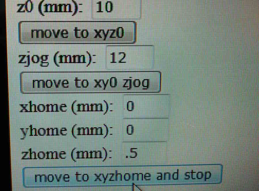
Some of the default parameters that are triggered when entering the SRM20 have to be changed. On the left pictures the default ones and on the right the change to be made.
6-Press calculate to see the job simulation.
7-Save the file.
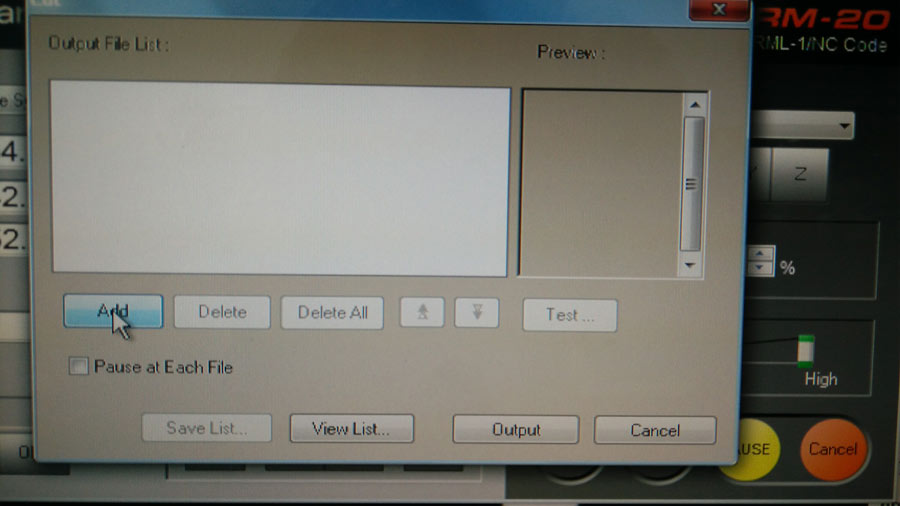
8- On the Roland SRM20 interface press CUT. Than deselect all (if there are files in the selection window they will be ereased), select the .rml file the fabmodule has generated and press ADD
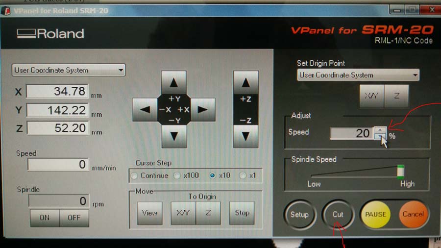
10- Press OUTPUT - Milling will start.
NOTE: It is convenient to ADJUST the speed to 20% at the beginning of the job to make shure it is all ok. It can be brought to 100% than without interupting the job.
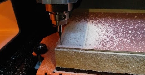
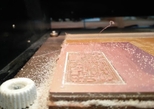
The dust generated by the end mill should be whitish in the whole area where the board is traced indicating it is milling through the copper layer. If it is not that means the Z axis needs to be redone and eventually forced down 1/10th of mm at a time until the dust is white.
Once the tracing is completed, I loaded the outline file on the fab module, set the job to PCB outline(1/32) end mill.
Do not forget to also change the end mill ( put the 1/32) on the spindle.
It is important not to move the board from the bed and not to loose the O on the X/Y axis.
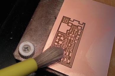
Once milling is completed the board has to be deburred -scratch out the chips of metal on the trace edges gently with a fine sand paper or a rigid flat surface. It can also be cleaned with alcohol to retrieve traces of grease.
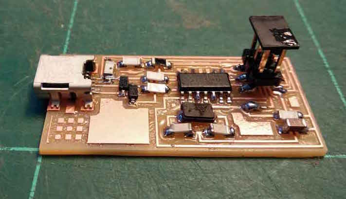
B_Stuffing the board
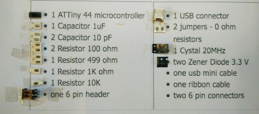
Stuffing the board consists of soldering the components onto the board in their right position and orientation. I selected each components and stuck them to a a sheet of paper where I have listed them. Component are small and can be easily mismatched.
Notes on components
The Mini Usb Connector -J2USB- will connect the FabIsp to the programmer. It is recommended to solder it first onto the board since it is the more difficult and risky.
The Microcontroller "IC1 t44" in the diagram is an attiny44a chip. There is a little circle on the chip that should be facing to the top left if the board is oriented in the same direction as Neil's diagram.
Crystals do not have polarity, orientation does not matter.
Diodes have polarity. The "C" or cathode end is marked with a tiny line. Important to place the side with the line on it over the "C" side pad in the diagram.
Resistors are marked with an "R" (R1, R2, etc).Resistors do not have polarity, orientation does not matter.There is a
code for resistors numbering
Capacitators are marked with a "C" (C1, C2, etc) Capacitors do not have polarity, orientation does not matter.
The components marked SJ1 and SJ2 are solder jumpers.
The components marked J1 ISP is the 6 pin programming header.Orientation does not matter.
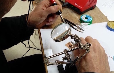
Welding the components to the board was a challenge as it is the first time I deal with such small components but alltogether it went well.
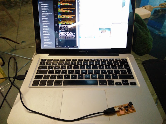
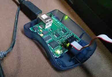
Once the stuffing was done I crossed my finger and connected the Fab Isp to the USB port of my computer and it worked.
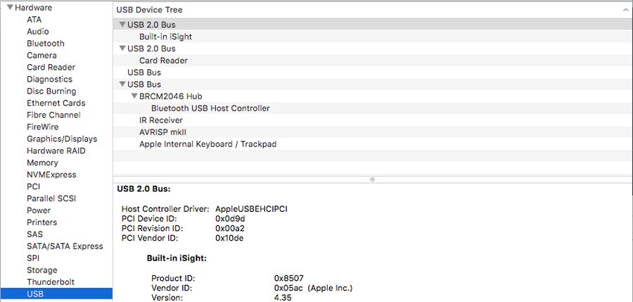
To verify the FabISP is connected and recognized by the system in MacOS go to : "about this mac" and open the system report window and click the USB device list. The FabISP should be listed. .
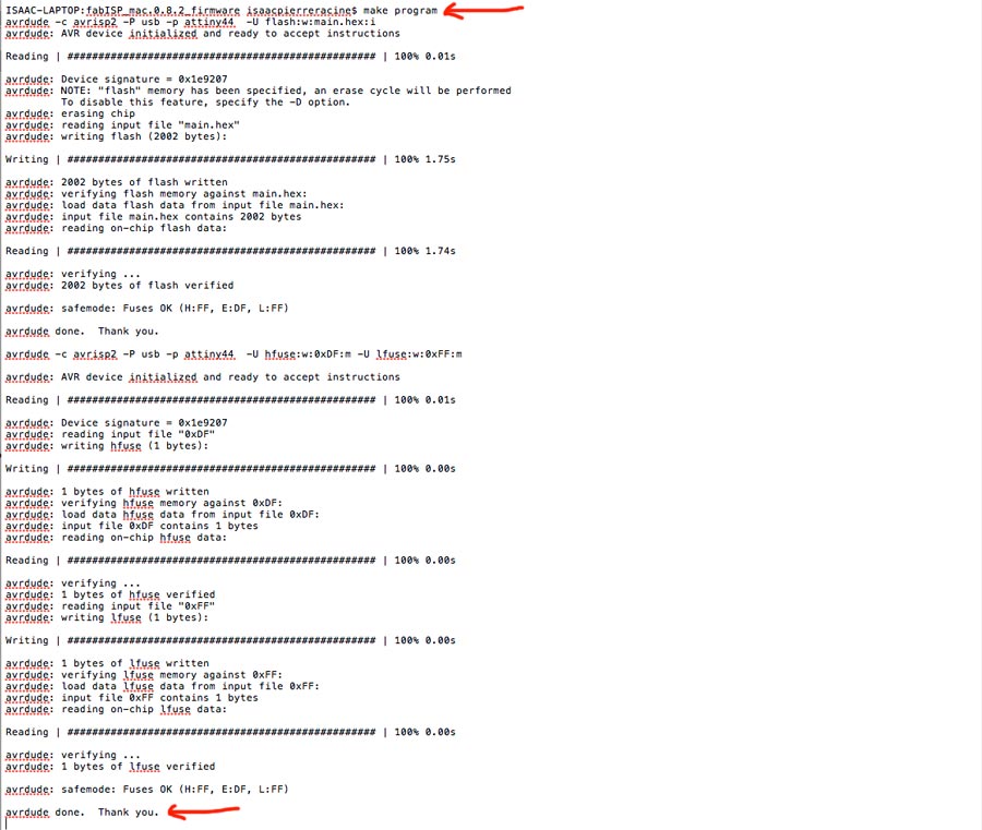
C_Programming the FabIsp
The programming consist in embedding the microcontroller with the capacity to be a programmer. This happen by connecting the usb port of the FabIsp to the computer and a AVR external programmer to the 6 pin hearder of the FabIsp. Once connected (programmer needs to have green light) a series of code needs to be installed into the microcontroller).All the necessary files are available in the Fab Academy web page .
I am running on a Mac so to program the FabISP I first needed to download and install the Crosspack AVR (it comes with the installer).
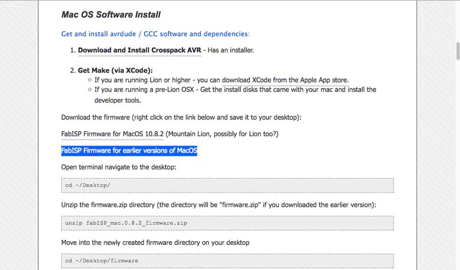
This last line of the the tutorials did not connected to the file that was unzipped. I realized it and type the correct command:
cd ~fabISP_mac.0.8.2_firmware

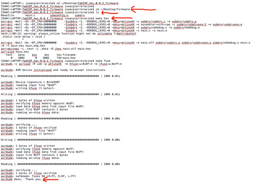
Then I could proceed with the make file (I already have the Xcode downloaded)
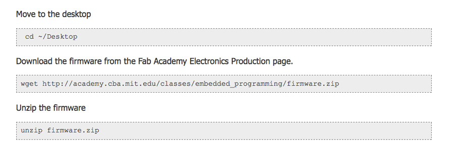
If any of the file need to be edited they can be opened in text file , edited and saved. Than run those files (the ones in the uncompressed firmare folder - in documents or download of the desktop otherwise indicated) from a console or terminal window.
From terminal go to the directory where the files are stored. Run the .hex file, than run the .hex file (in terminal type: make hex), than install the fuse (make fuse).
Once the FabISP is programmed it can be used to program other board. It will be helpful during the next electronic assignments.
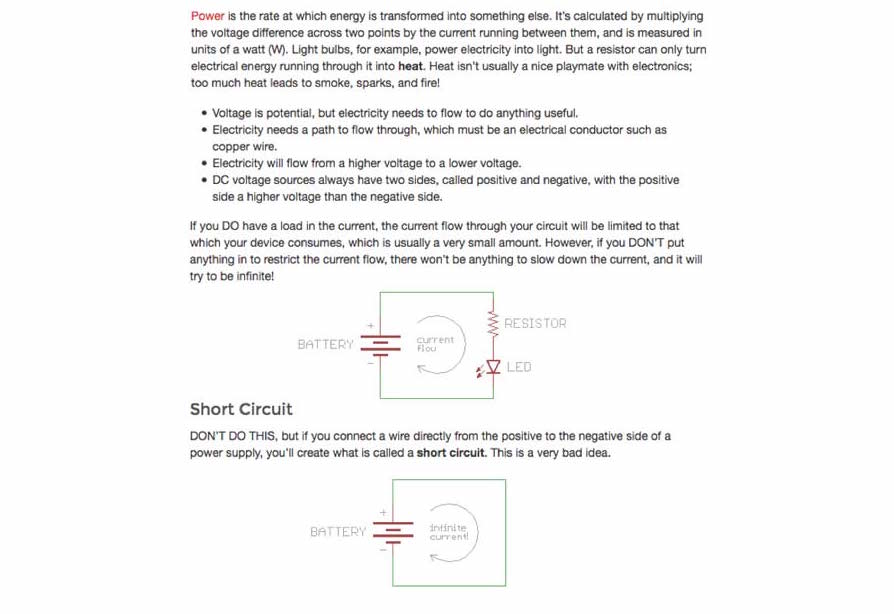
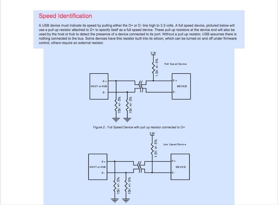
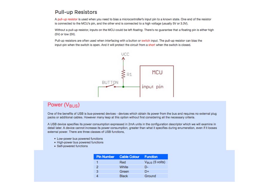
I also reviewd basic electronic notion and concepts. as this is all new to me. I got my source here: Demystifying the FabISP and Designing the FabOptimus

Additionally
I spent some time adapting the CSS and HTML of my web site; adding a Fab Academy logo on the splash page and on the assignment's pages.I also decided to use the paragraph commend instaed of the h3 as in the previous page. But I did not have time to integrate thses changes in the previous pages. I also want to add a licence to the web page but yet did not have time to do it. Those 2 items remain to be implemented.