20 - final project
digiTalog light sculpture
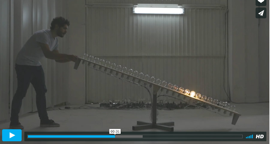
I am creating a similar sculpture on a smaller scale - reducing the size and using a neopixel led strips instead of incandescent bulb lights.
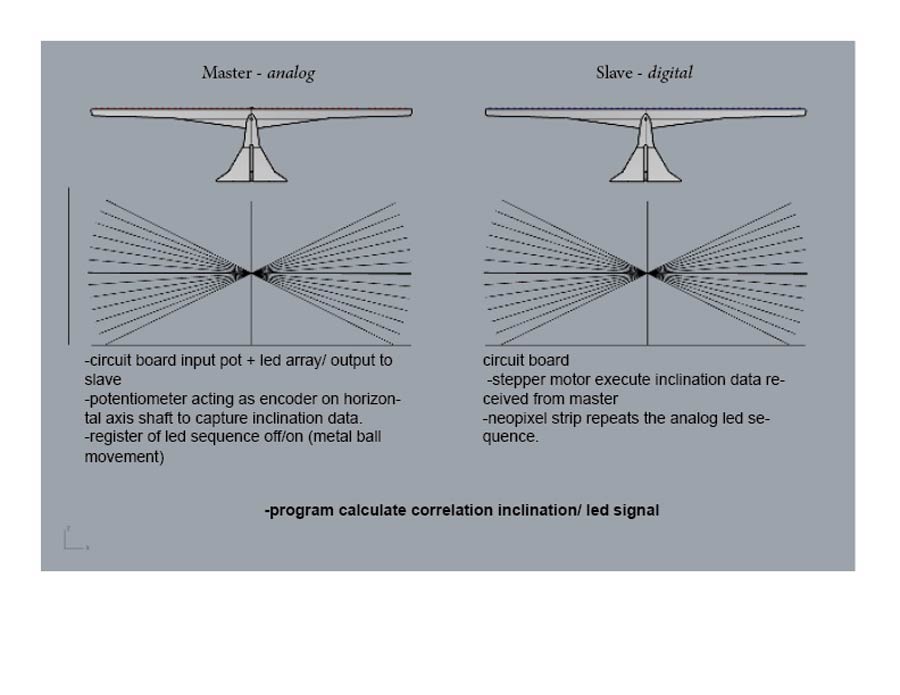
My final poject is a research prototype of a sculpture that will include a "digital" (master) and a "analog" (slave) units linked together so the user can control the digital unit by actuating manually the analog unit. The dialogue between the two units and the user aim to materialize a feeling technology provokes in me: a contradiction between empowerment and slavery. It is an exploration of the complementarity between the analog and the digital - the sculpture beeing a medium of this experience.
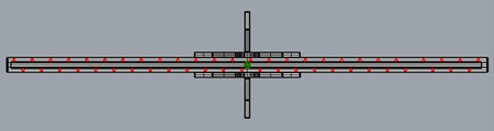
The analog unit will be operated manually. A series of leds placed along the bridge will light up as a metal ball travel along the bridge (in a groove) following its inclination. A potentiometer - linked to central axis of the bridge through a gear system - will provide a reading of the inclinaton of the bridge. A series of resistors - one per leds and each with a different value - will generate signals indicating the position of the metal ball. The correlation of these datas (output) will serve as "input" to actuate the digital unit.
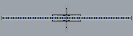
The digital unit will replicate the movement of the analog unit. A neopixel led strip will replace the leds and a servo (or a stepper) motor will actuate the inclination of the bridge. A program will compile the datas received by the analog unit and send them to the digital unit.
The recitation on Why Make Almost Anything has inspired me to create this project. It connected with my inclination to reflect on the role of technology and its control over our life experience. I am creating a machine wich has no formally practical purposes but that can engage the user into a dialogue with the machine.
Hybrid version
As I consider making both units to ambitious of a challenge for my fnal project, I will create an hybrid version of the sculpture through which I can apply various Fab academy processes while many important challenges I will face when making the complete version of the sculpture. The physical structure is designed in Rhino (3D design) and the different parts will be CNC milled and 3D printed. I will create a Attitiny44 based PCB for electronics and program the correlation between the neo pixel leds and the potentiometer using an Ardino IDE script.
I will intend to interface visualization of the datas using eiter procesing or python.
Making the hybrid DIGITALOG light sculpture
The objective of this version is to create a prototype of the sculpture design and establish an interaction between the inclination and a neopixel strip (attached to the bridge of the sculture.
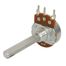
I have considered different options to capture the inclination data. I looked into giroscope, accelerometer, optical sensor encoders and rotary encoder sensor. I have finally decided to use a potentiometer - integrating it in the mechanical horizontal axis. Technically speaking an accelerometer may have been a better choice but for easthetic and mechanical reasons I prefer the potis.
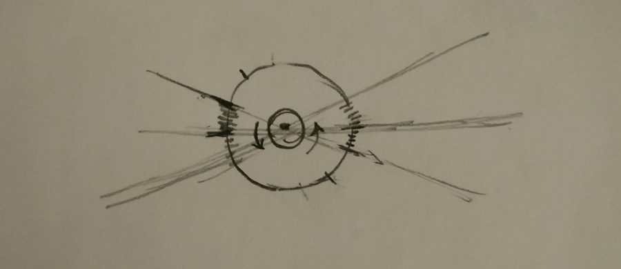
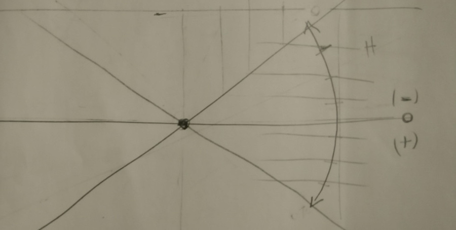
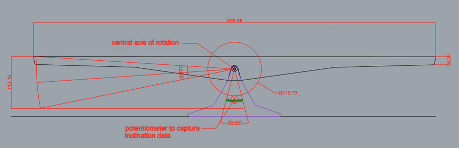
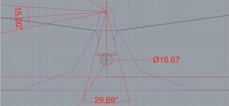
After drafting the design in rhino I created the gear system that will generate the inclination datas. Since the maximum inclination of the bridge allow only 15ª(I want the center of gravity to be fairly low) I need to create a system that multiplies the gear ratio between the potis shaft when the axis of the bridge. This will help get more accurate reading and precision in sincronizing the inclination and the neopixel sequence. It will also help getting precision in syncronizong the the metal ball position with the bridge inclination in the analog version, and the motor and the neopixels in the digital replica.
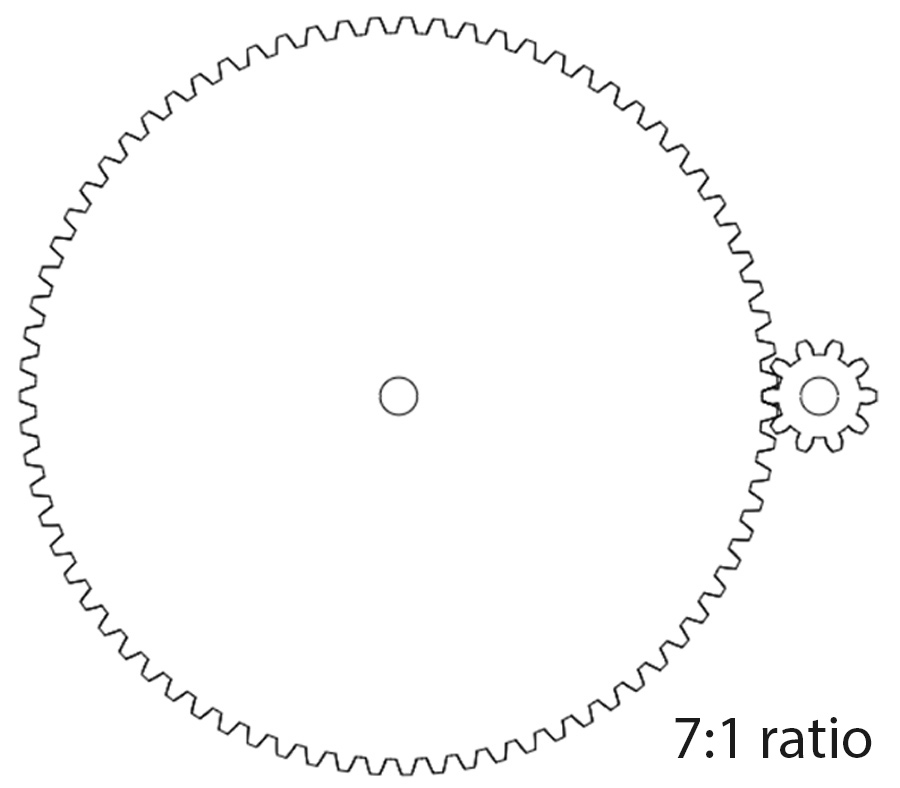
The distance between the central axis and the position of the potis allows the big gear to be maximum 120mm diam in order to get a 7:1 ratio equivalent to 90ª rotation of the small gear (potis shaft) when bridge moves from minimum to maximum inclination.
Starting with the maximum diameter of the big gear and the ratio desired I calculated the number of teeths for each gear based on this formula.
Than I did some math to deduct the diameter of the small gear and the number of teeth for each gears.
120mm x 3.14.16= 376.99mm circumference (377)
15º rotation = 360º/24= 15.70mm circumference.
15.70mm is the distance the big gear (120 mm diam.)can travel while inclinating up to 15º.
If I want the small gear to rotate (at least) 90º when the big gear rotate 15º I need the circumfrence of the small gear to be be at least 3 x 15.70 = 47.1 mm. (3 is the 1/3 of 360º).
47.1/3.1416= 15mm.
15mm. is the diameter of the small wheel.
I want the gear teeth to be as small as possible but that can resist some torque I set a tooth spacing of 5mm.
Big gear: 377/5 = 75
Small gear: 47.1/5 = 9
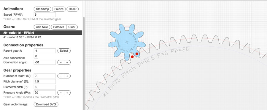
I used a free online Gear generator to produce the gear designs. I also refered to this wood gear generatorto study how gear works.
The workflow to generate the design and import it to Rhino is the following:
Create both gears by entering the amount of teeth for each one.
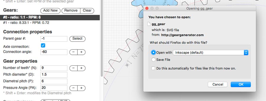
Download the SVG file.
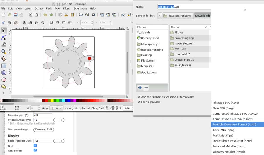
Open the SVG file in Inkscape.
In Inkscape save it as a PDF
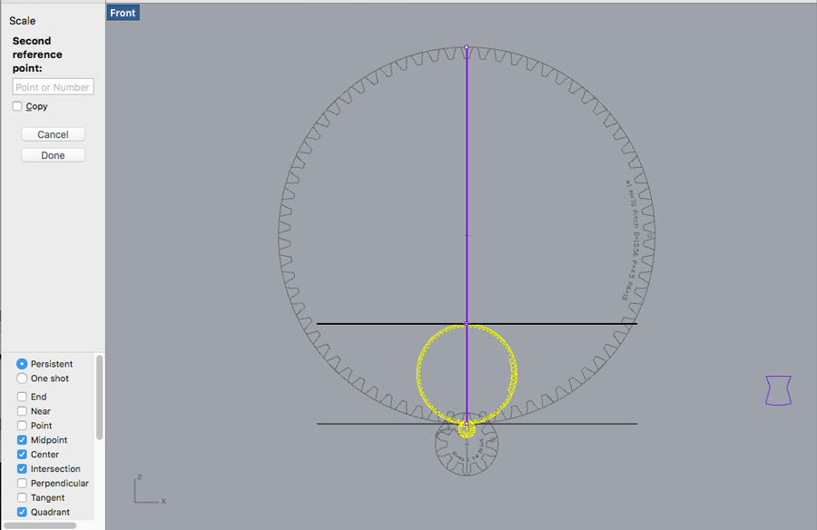
In Rhino import the file.
Match the gear together in Rhino and scale them to the desired size. I repeated this process for both gear and matched them in proportion into the drawing.
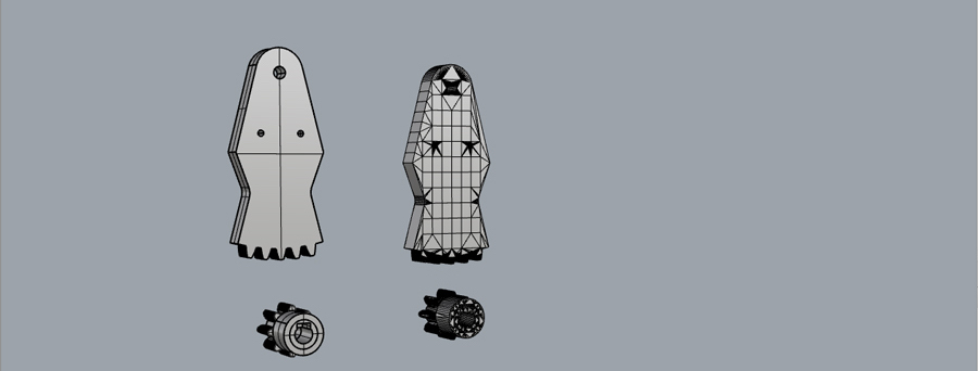
I tried out few combinations and ended up adjusting the big gear to 70 teeth and the small gear to 8 teeth with a final diameter for each gaer as follow:.
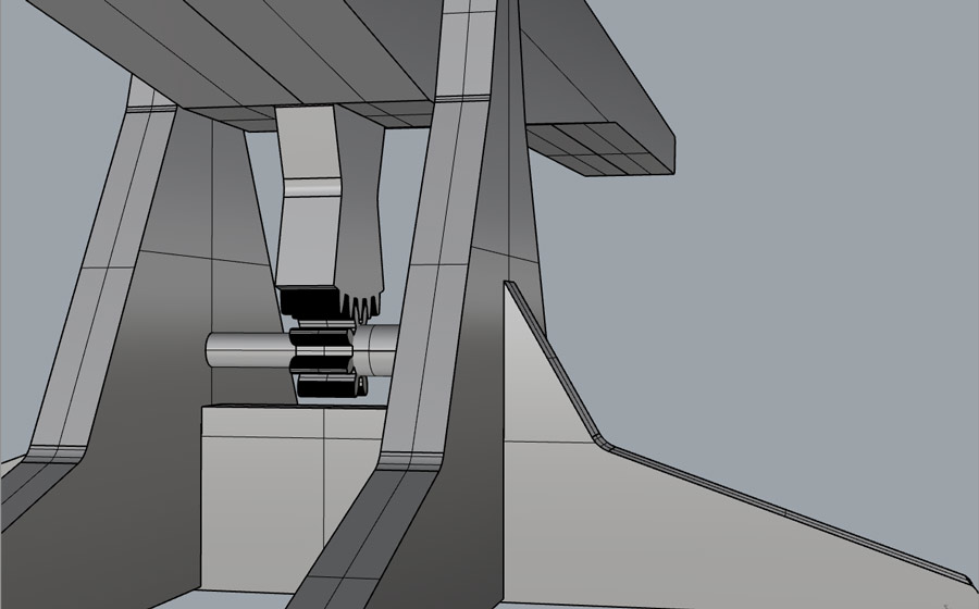
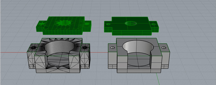
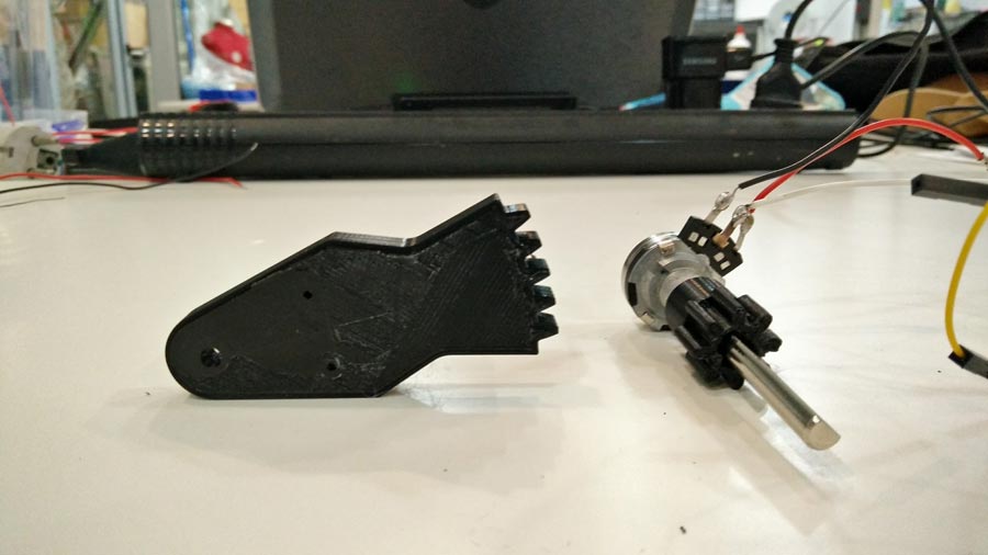
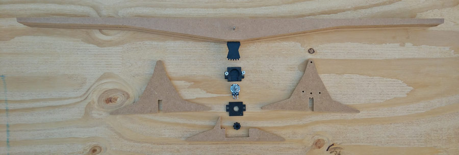
I generated a 3d model of the 1º unit integrating the potis, its holder and the gearing system so I can extract the parts to be milled and 3d printed.
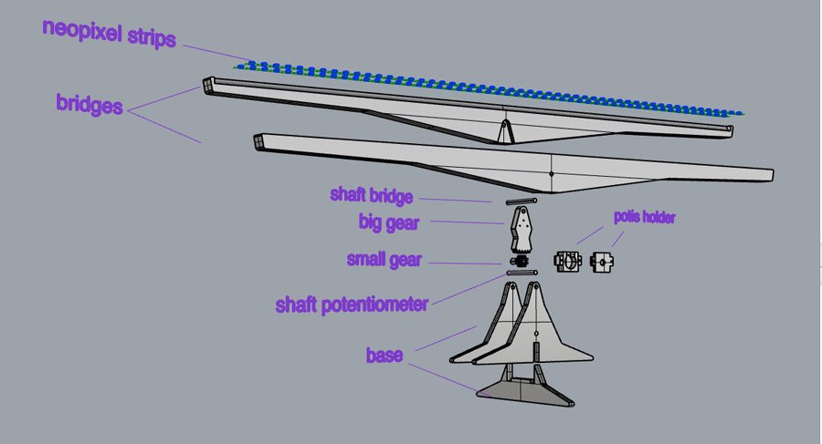
The element composing the mechanical part of the sculpture are:
The electronics
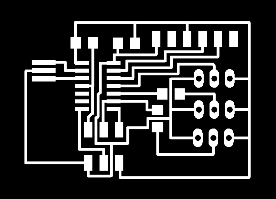
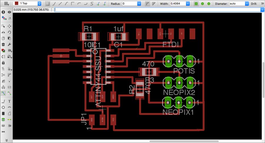
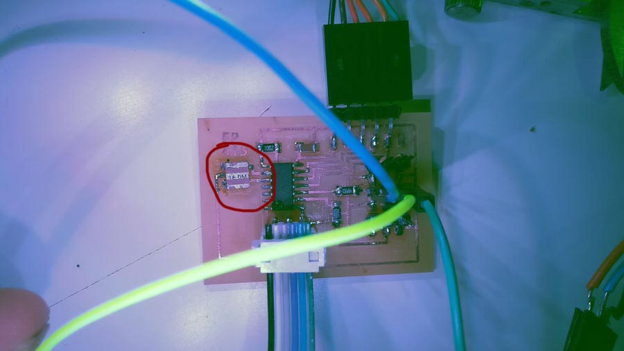
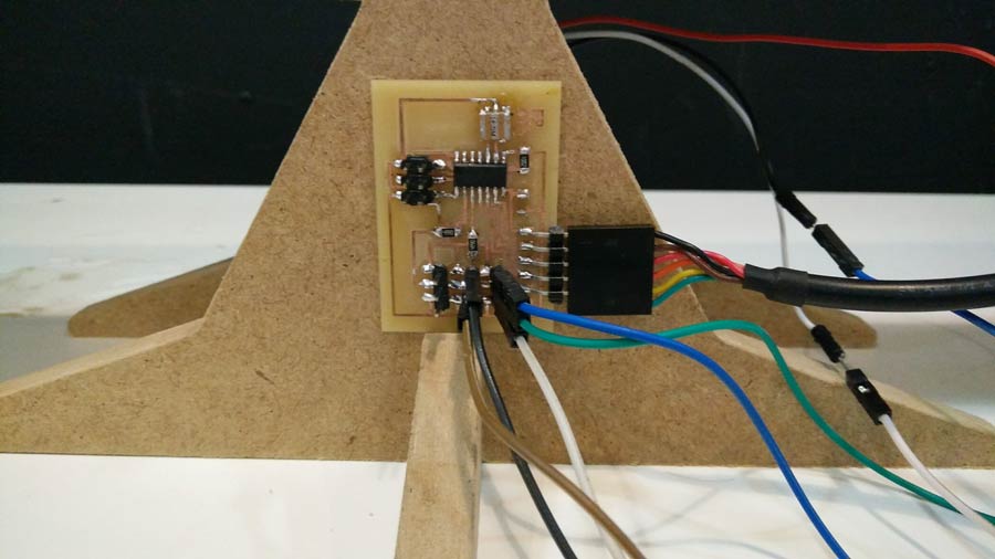
For the electronics I decided to make a generic board to test the system. This board includes 2 serial communication output pin(RX,TX), 2 outputs (for neopixel led strips and else) and 1 input for the potentiometer.
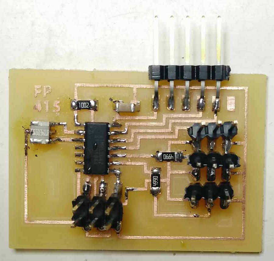
I am be using a Attitiny84 microcontroller. I designed the board taking in consideration further iteration of the circuit where a a servomotor, a voltage regulator and a 4 pin header for 9 volt battery can be integrated. I left 4 pins left free if I need to add more peripherals including the miso and mosi pin. The board is designed in Eagle and milled on the Roland SRM20. I met no problem milling and soldering the components.
Test programming the circuit board.
I burned the bootloader sucessfully at once and went on testing the functions of the board by running basic programs from Arduino IDE.
First I tested the connection of the data pins for both outputs and input by connecting the potis to the board and an blinking led on a breadboard to my board.
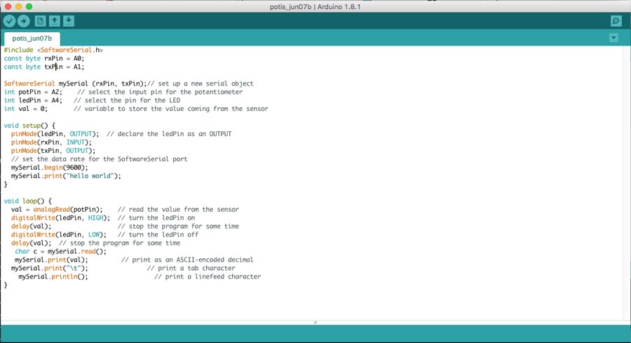
The Attitiny84 do not work with standard "serial.begin" but needs to run the "software serial" library to communicate with serial monitor. I created a simple sketch to comfirm I get a reading of the potis values in the serial monitor, and turn an led on.
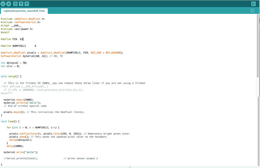
Than I downloaded the Adafruit Neopixel library , installed it and created a basic sketch for a 6 led neopixel. After testing and failing to connect the neopixel to the board I figured a few important issues:
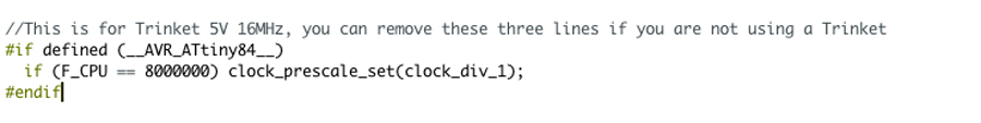
1º to run a neopixel with Attiny a trinket has be inlcuded in the code:
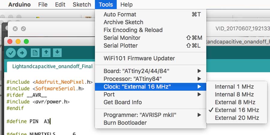
2º The Trinket mentions "5V, 16MHz. That means the Arduino IDE clock need to be set to external 16MHz.
But my board has a 20MHz resonator and when I tried to set the Arduino at 20MHZ I received an error meesage saying there is not enough CPU power. So I changed the 20MHZ clock on my board for a 16MHZ - I was lucky to find one in the invetory at the bottom of a little drawer.
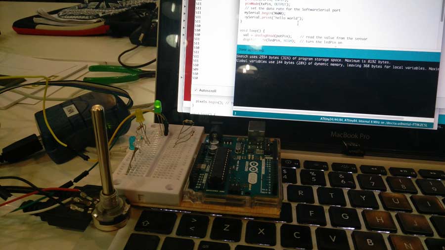
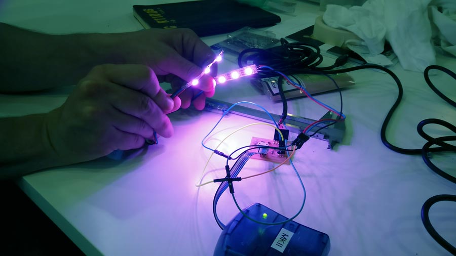
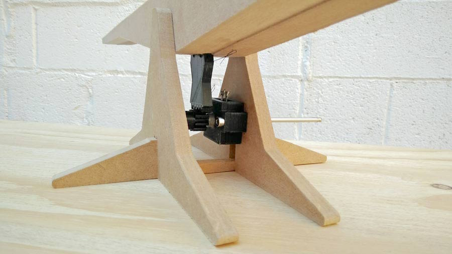
With the 16MGHz I could run the sketch perfectly and the 6 neopixels on the strip light in the desired color (white - in the picture the pink hue is due to color balance of the camera) .
All the components are working: potis, 2 neopixel output. The next step will be to program the neopixel to execute a sequence (pixels to lit one after the other in a specified order and link the potis value to the neopixel strip).
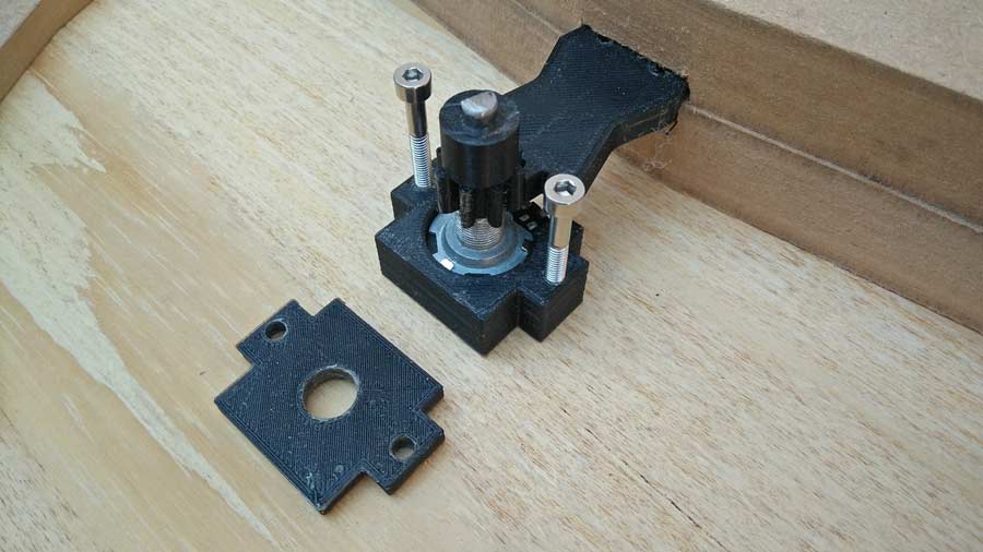
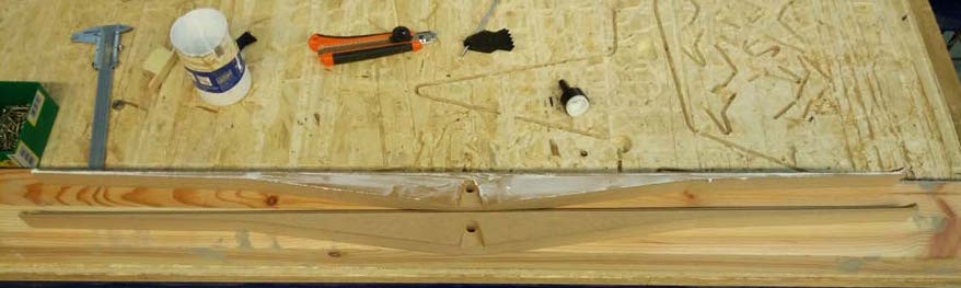
Milling and printing
Working in spirale I left the electronics for now and moved onto fabrication. 3D print the gears, potis holder, prepared the Cam file and milled the base, the bridge, and assemble the elements together.
The 2 pieces of the bridge are glued together with standard wood glue.
Many details of the designs had to be altered manually during the assembly. That includes the base beeing cut down to receive the potis holder, the sizes of the holes of the potis holder had to be drilled to 4mm, and the pocketing to receive the pundulum gear was way wrong.
This iteration serves me to understand the flaws of the design and also to recognize more clearly the design rules. It is a creative process and some errors suggest the creative dynamic of the unconscious. For example the fact that the end of the bridge be so thin makes is weak physically but brings a lot of delicacy.
I need to review the rhino files to resolve some design problems and adjust the file according to the changes needed in the assembly. Also I need to integrate the electronic and complete the design of the whole piece.
Data input
In this section I focus on capturing the datas from the potis and translate the movement of the bridge to 1 strip of neopixel leds. I first connected the circuit board to the potis and to the computer to make shure I can read the value as it balances.
I refered to AdaFruit Neopixel tutorialto start with the coding of the neo pixels. It is well explained and guides through the coding process.
I searched the following sites to understand the best way to program each led to lit according to the potentiometer value.
using-a-potentiometer-to-control-number-of-lit-pixels-on-an-neopixel-strip
neopixel control with potentiometer
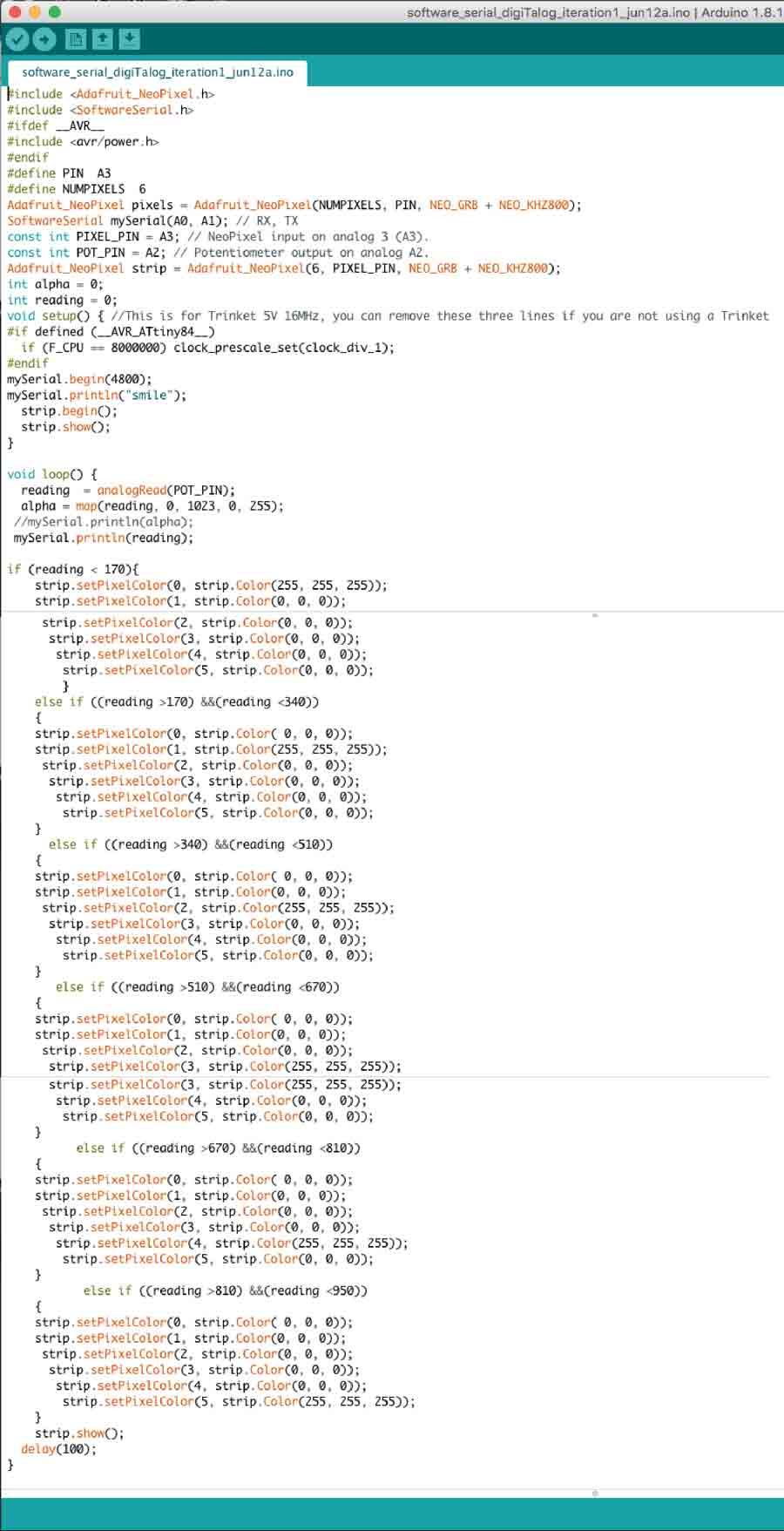
The sketch I made is a compendium of the 2 above mentionned reference. The iteration process was:
1º to make the potis fade the pixels in and out using the potis.
2º make some of the leds (calling the led number) fade in and out
3º Make 6 leds turn on one after another using the potentiometer.
It took me a while to figure it all out and mostly a way to have only one led at a time to lit in a sequence and according to the potis reading. I used the "map" function to capture the potis reading and the "if" and "if else(())" function to sequence the neopixels individually.I knew it was the "funky way to have the neopixel do what I wanted but I did not yet had to mind to get into a more complicated code.
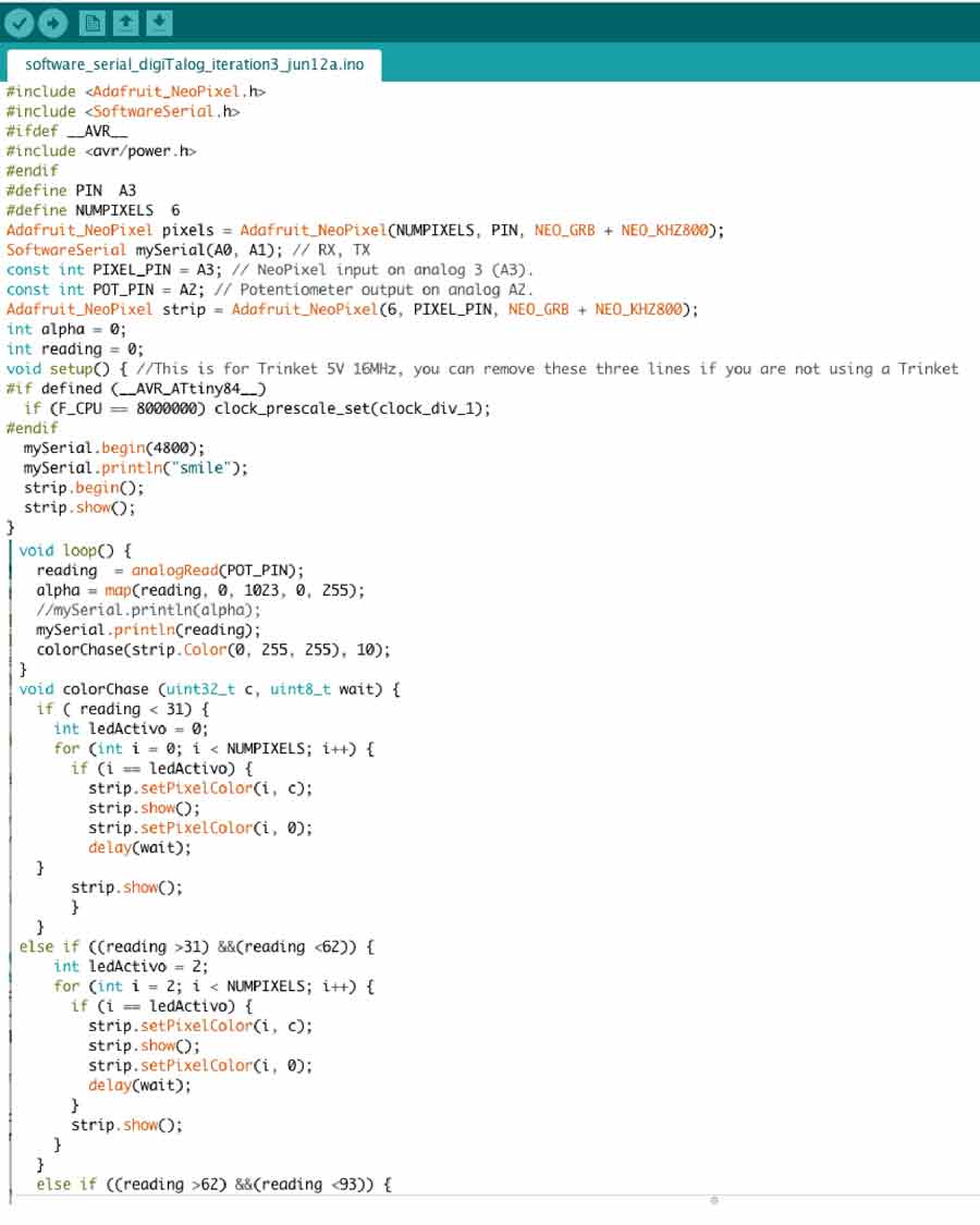
Knowing I could not repeat this last code for a large number of leds I researched and rewrote the code to simplify the synthax using the chase function from this tutorial:chase the dot down the full strip :
void colorChase (uint32_t c, uint8_t wait) {
One thing that is very important working with neopixels is to add the
"strip.show();" function for each individual routines.
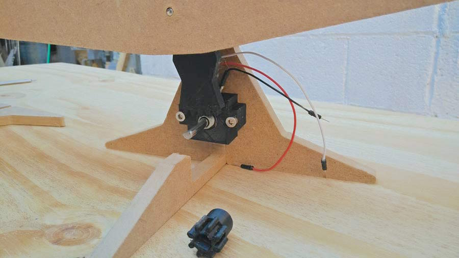
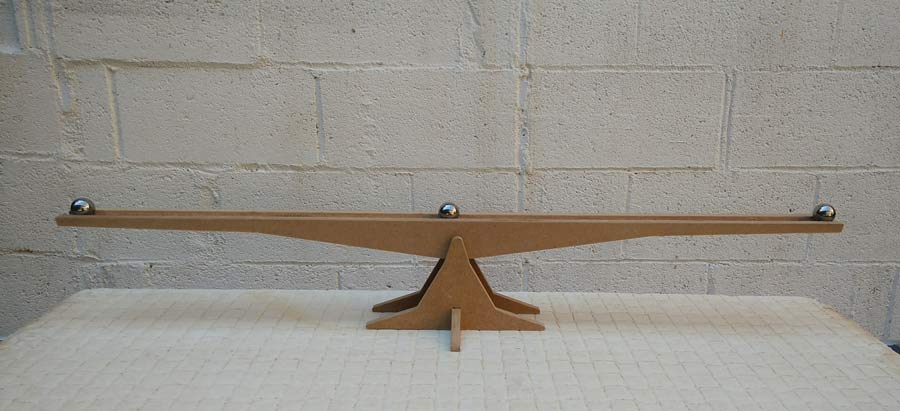
Now time to connect the analog unit to an actual neopixel strip. The one I have has 60 leds. The lenght of the bridge is 88 cm and I programmed one led out of 2 for the moment.
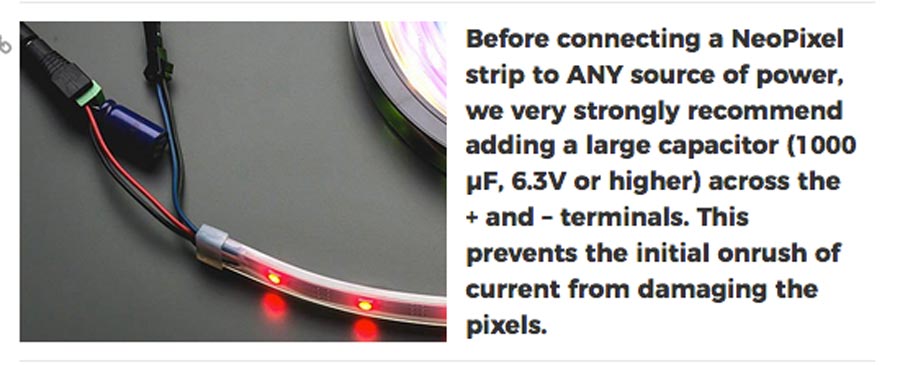
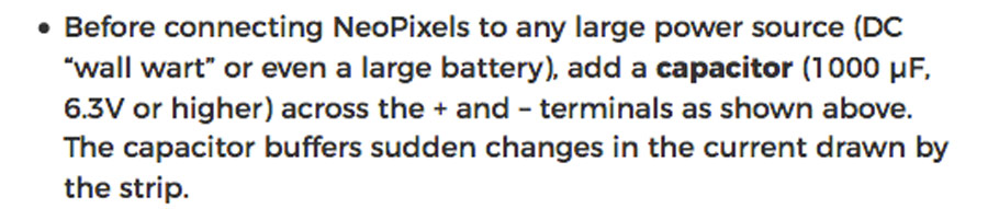
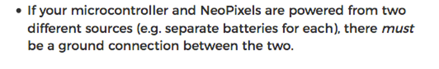
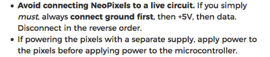
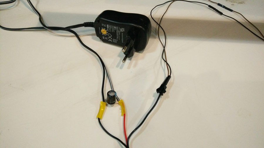
There are specifics to connect a Neopixel strip to the microcontroller as well as to a power supply.
I was only missing the 1000Uf capacitator. There is already a 499ohm resistor on each pin assigned to the neopixel on my board.
In the following videos we can see how the inclination of the bridge is linked to the neopixel sequence. Now the challenge is to make the light sequence according to the movement of the metal ball.
neopixels on bridge
analog + neo pixels
analog + neo pixels
Making the analog version and capturing the datas is the next objectiv. As going along with this I will review some strategies adapting to the conclusion I meet on the way and defining the aesthetics for each unit.
Designing the wiring the bridge with diode pixels so they turn on and off along with the passage of the metal ball. To capture these datas I am considering charlie plexing but I have not come to a conclusion yet. The objectiv is to have the datas of those leds will be coded along with the potentiometer value to program the digital unit.
Presentation
Abstract
DigiTalog is a fabsculpture that replicates the analog into the digital. It consists of pair of apparently identical artifcts capable of interacting with the user and with eachother. User actuate the analog unit manually and sees its action replicate into the digital one. A ludic experience as the dialogue evolve into a choreography of light and movement. The interactiv functions are dynamics and coded to be altered or even reversed in an aleatory way constantly questioning the hierarquy between man and machine.
I have just recently decided to make this idea into my final project and I am still in early stage of its realization. More than "final" I consider it as another Fab Academy assignment, an opportunity to integrate the processes learned throughout the semester but most importantly to apply the methodology acquired during the program. I have a very clear idea of what I want to create and trust the spiral process of iteration will bring solution that accomplishes creative satisfaction.
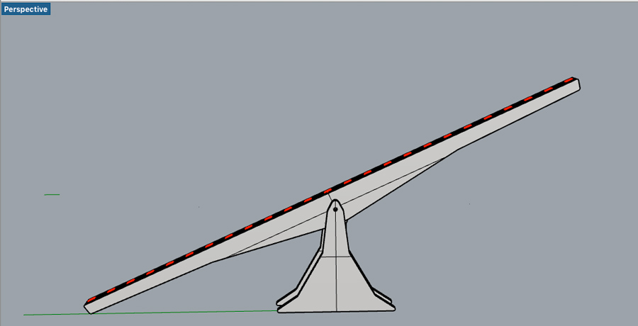
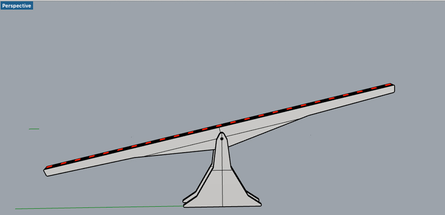
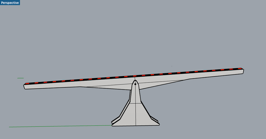
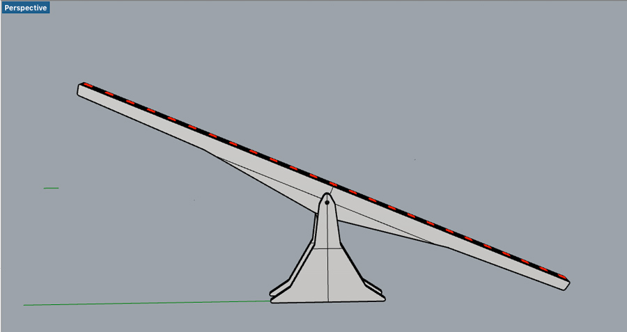
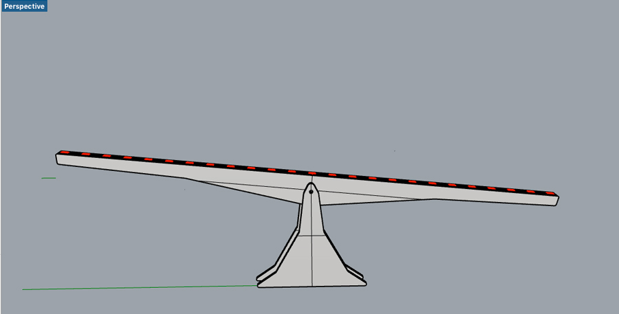
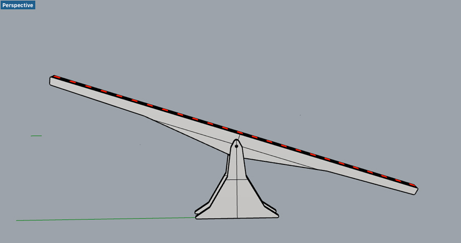
I started by creating a first draft of the structure and experiment and develop the technology that will be used either in the analog or in the digital replica. I designed a basic (and non definitive) structure that convey the idea of equilibrium and balance. I am interested in keeping both machines as similar as possible - like if they were twins - from far apart they look the same but once close and with the experience their difference become so obvious. I am designing the elements in Rhino. The structure is CNC milled (MDF 9mm for the base and 25mm for the bridge) and the other components are 3D printed. I have made an Attitiny84 circuit board with a potentiometer and 2 outputs to neopixel strips and programmed it in Arduino Ide so the potentiometer's controls the sequence of led turning on and off.
This iteration serves me to proof the concept and pull conclusion towards a defenite design. My idea is to place a copper vynil trace on the analog bridge so when the metal balls passes the leds turn on and to connect the leds to acharlie plexing as input on the circuit board. Those datas in correlation with the ptentiometer value will generate the code the digtal replica execute. I this case the potentiometer will be replaced by a stepper motor.
Additionally
I have learned to export video with terminal command lines using ffmpeg. It is useful to reduce the video size, choosong codec, bitrate, etc. Here is the line of code I prompted: ffmpeg -i presentation4.mpeg -c:v libx264 -crf 24 -preset slow -c:a aac -b:a 192k -ac 2 out.mp4.
-1 = name of the video with the extension
-c: =H264 library
-crf =24 frame per second
-preset slow = use low quality preset from library
-c:a = acc
-b:a 192k
ac 2 = output video name + extension
Download the files here