

Week 6
.jpg)
Week 6 Description:
Week 6
Electronic Design
Assignment:
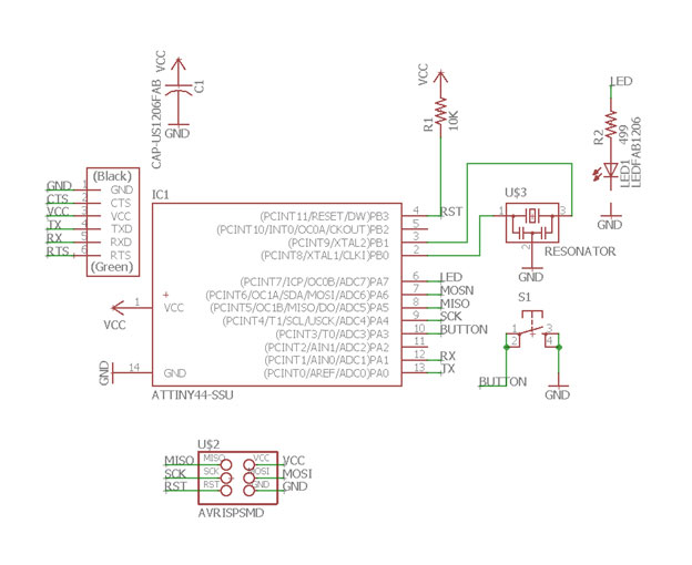
Redraw the echo hello-world board
-Add (at least) a button and an LED (with current-limiting resistor)
-Check the design rules, and make it
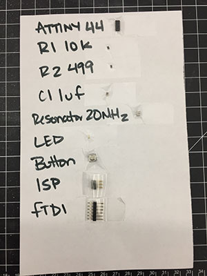
Components:
Inventory- DigiKey
Ribbon Cable: Paralel conductors, also used as hook up wire (can be pulled apart)
Push Button (Switch): Connects a function while pressed
Slide Switch (Switch): Stays in position until you slide the switch back
Resistor: I=V/R * Set time scares
Capacitor: Unpolarized voltage in both directions, Polarized voltage in one directions *part of circuits that set time scale
Super Capacitor: Limited in voltage/polarized, they store a huge amount of chare and battery-not for timed
Resonator/Crystals: Tell time – need 2 capacitors, 20 MHz=2000 per
Inductor: V=L dl/dt (less common) They also pass slow signals and block quick ones
Diode: Mark on one side. Current flows from anode to cathode, used to make sure current flows in one direction.
LED: Light on board
Transistor: Mosfet, Rds- resistance between drain of source, P = I²R
Regulator: One side goes to ground, one goes to output (input to micro controller)
Amplifier: Micro controllers have these inside
Microcontroller: Mini computer chip
Free Pins: Add switch (PA7/PA6) Add LED (PB3/PB2)
EDA: Designing Circuits
-Start by drawing schematic
-Place items on the board
Test equipment: INSTEK GDS-1152A-V, Digital Voltmeter
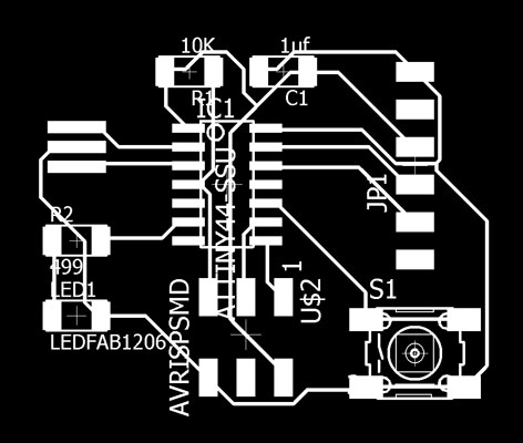
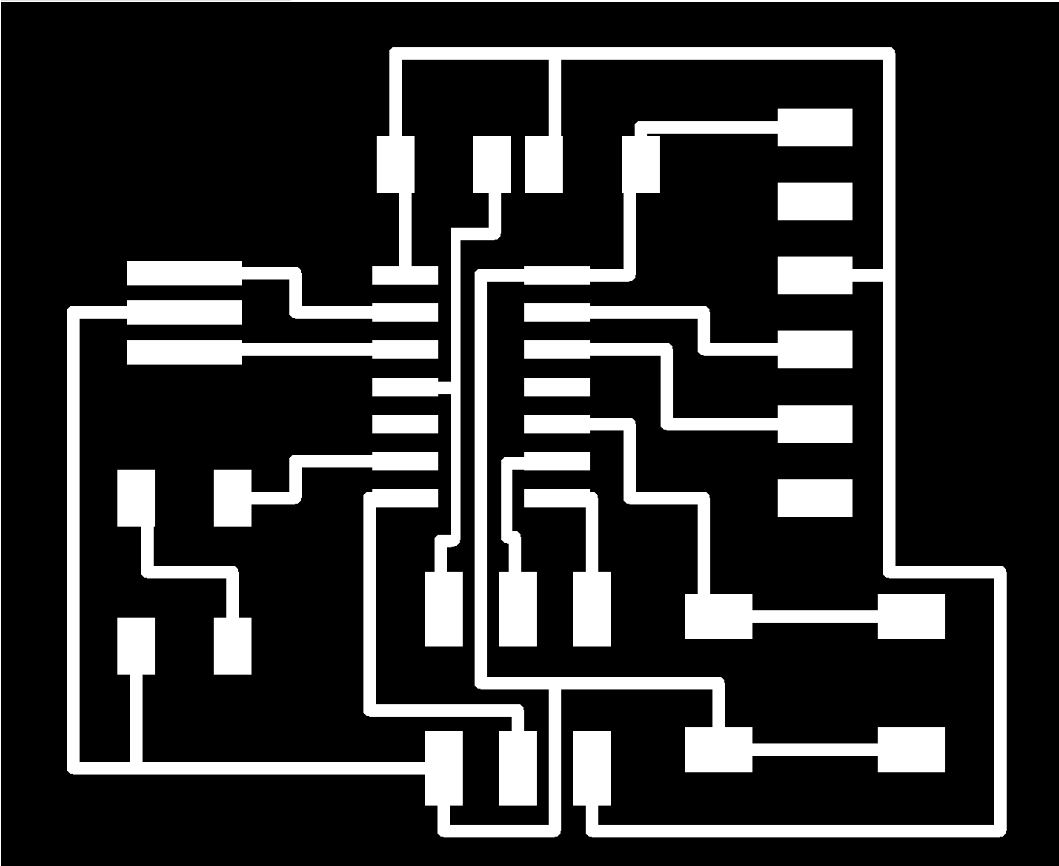
To draw the Circuit I used Eagle – The components were designed and placed in a library fab.lbr
Learning Eagle (Autodesk) was a challenge, but the program made sense once I got started.
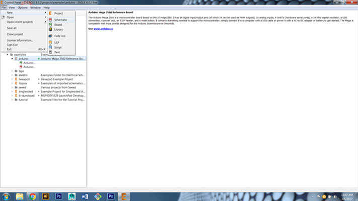
- First I downloaded the program to my desktop.
- File
- New
- Schematic (Where you will add parts and connect them)
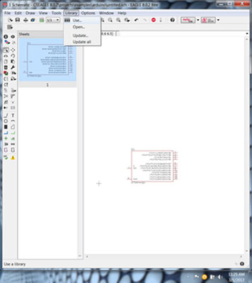
- Add the fab.lbr
- Library
- Use
- Fab (under EAGLE 8.0.2
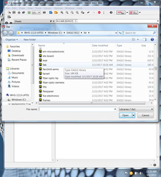
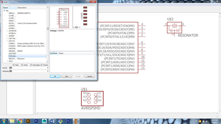
- Edit
- Add
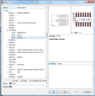
- Find fab library on list
- ATTINY44
- Click Ok
- Place the part on the workspace by clicking
- Hit Esc to go back to the Add menu
- Find all of your parts
- The GND and VCC were not in the fab.lbr so I searched for them
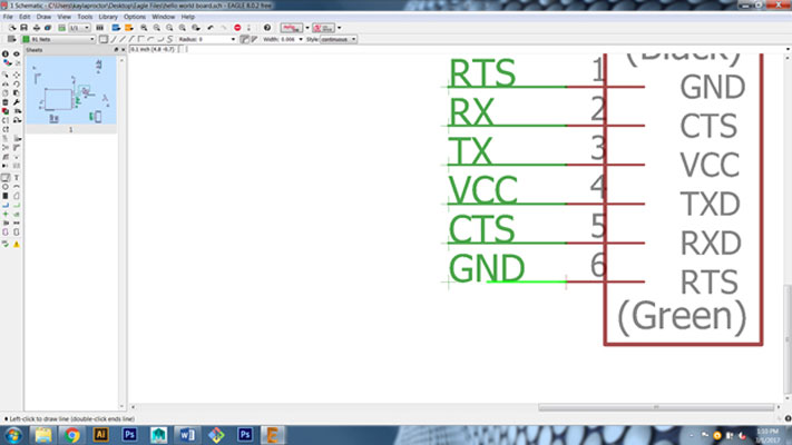
- Change the values using the button that looks like a fraction with the lower portion highlighted
- Change the names with the button that looks like a fraction with the upper portion highlighted
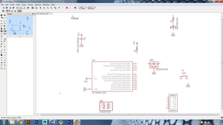
- Then I reworked the components and labeled the components with the button that has a green line slanted with text on it. Once I did that they started linking together
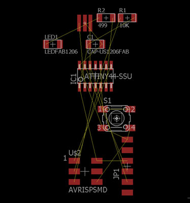
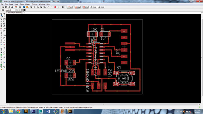
- I then changed to the board view
- I moved, rotated and reworked the components to minimize the yellow lines crossing over and to maximize the space on the board.
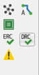
- Then I pressed the Autorouter Tool (which I found out later was much harder then just drawing the connections myself) - I went back later and right clicked - Route - Connections will show between the parts to complete the board. I also changed the width of the wire in the settings to 10 to make sure that they were not to thin and wouldn't mill well.
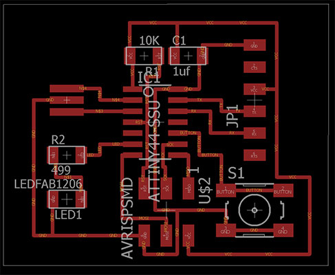
- After 8 attempts at reworking and saving my files I finally had no overlapping blue lines.
- File
- Export
- Browse and save as PNG
- Name file
- Monochrome
- 1000 dpi
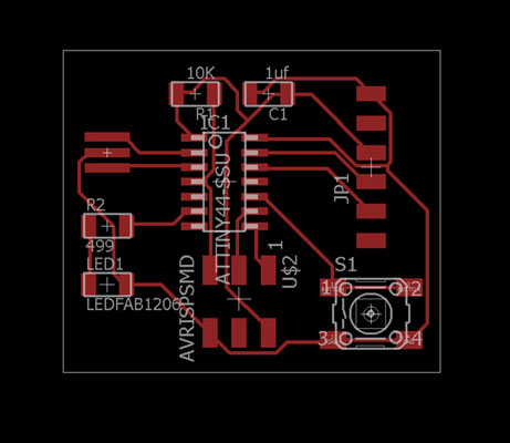
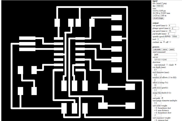
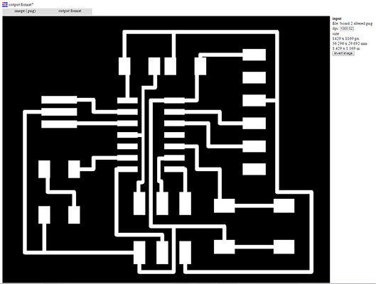
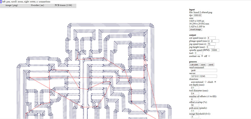
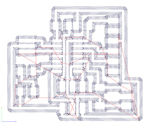
- Fab Modules
- PNG
- Hello world board final.png
- Output format
- G-Codes
- Process
- PCB Traces 1/64 (Outline 1/32)
- Calculate
- Save to flash drive
- Take flash drive to machine/computer
- Follow directions from WEEK 4 as how to machine the FR1
- In order to fix the FR1 to the plate it sits on I used a industrial strength 2 sided tape.


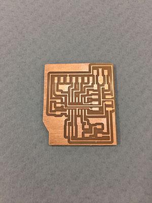
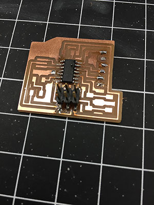
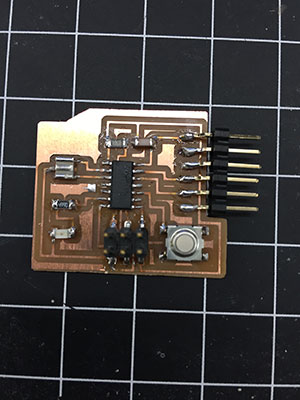
2nd Time Designing the Board: Here are some images from the second time through desiging the board and using the CNC Mill with the FR1 and the soldering process.

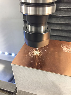
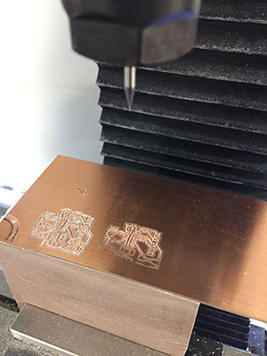
As you can see from the photos above, I ran into a a few problems with our CNC mill this week. We had a large event in our space this weekend and the company who had donated the mill asked us to move it to a different location for people to see it better. After we moved it things were not working as well as they had before this. We did mill the block that is holding the FR1 in the new position so that it was flat and it did seem to help in the new position. The block that I was using wasn't level and when I zero'd the mill it then moved to start the milling process and was too deep in the FR1. There were a lot of bits broken in this process and a very frusterating week! Once the mill was moved back to its original location the company (Tormach) also had a few updates. It was after all of these steps I was able to get a clean board and no broken bits!
To test the board:
Go to Fab Academy Archives
- Schedule – Week 6 (where files are located)
- Assignment
- Echo hello-world board
- hello.ftdi.44.echo.c
- hello.ftdi.44.echo.interrupt.c
See my steps in Week 8 where I tested the board with the files listed above.
Week 6 Photos