While designing our company's mobile makerspace/Fablab, we faced one challenge which typically every makerspace or lab faces , that is,
1.Which tool is available ?
2.Who has taken the tool?
3.How to secure these tools?
There are hundreds of valuable tools available for use and these tools go from one person to other and to other and many times we are never able to hold anyone responsible for the damage or the loss due to no track of records. Also, its not placed at one place making it very difficult for the organiser to organise them to their original place which is either a table or a box.
Be it home, office, makerspace or a fablab or any lab with tools, If you are a user of tools you will always end up losing those hammers under your stuff or forget where you kept your drill or not even keep it back to its place and as a owner or management of such place you will always want to keep track of such expensive and necessary tools in your lab or workplace. Also, it would be wonderful to even know who took it and to get aware about any unauthorised person using them .
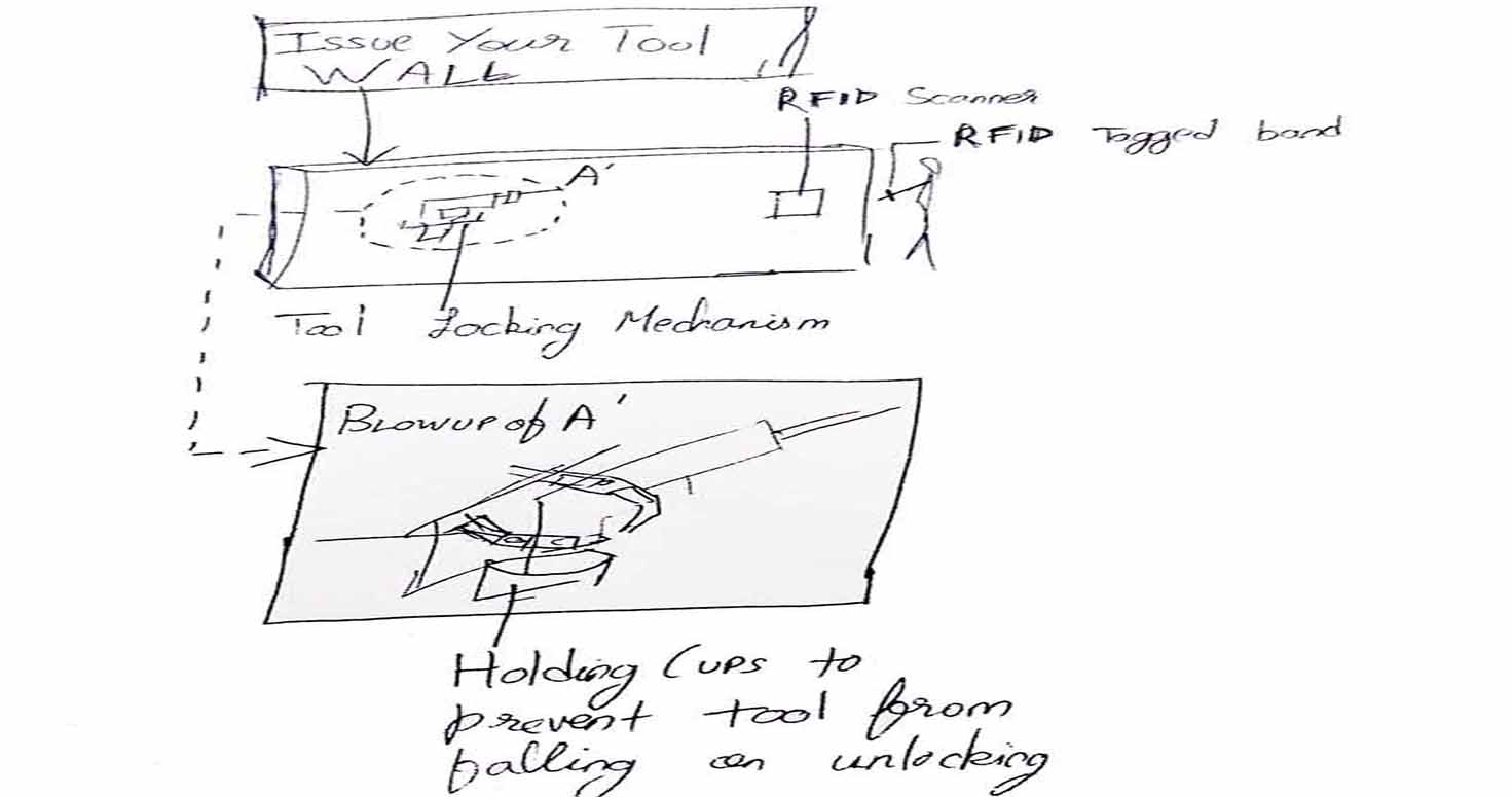
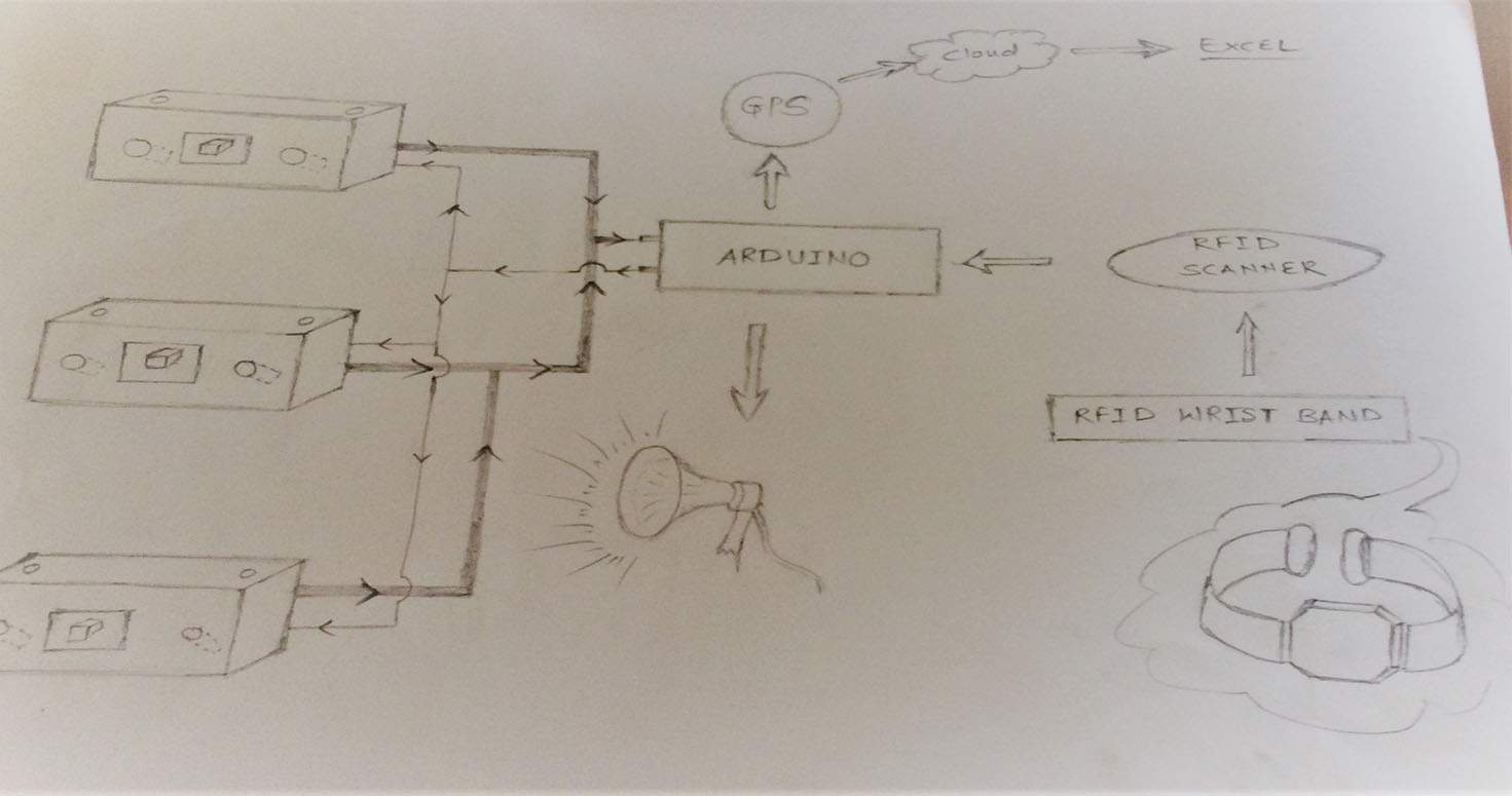
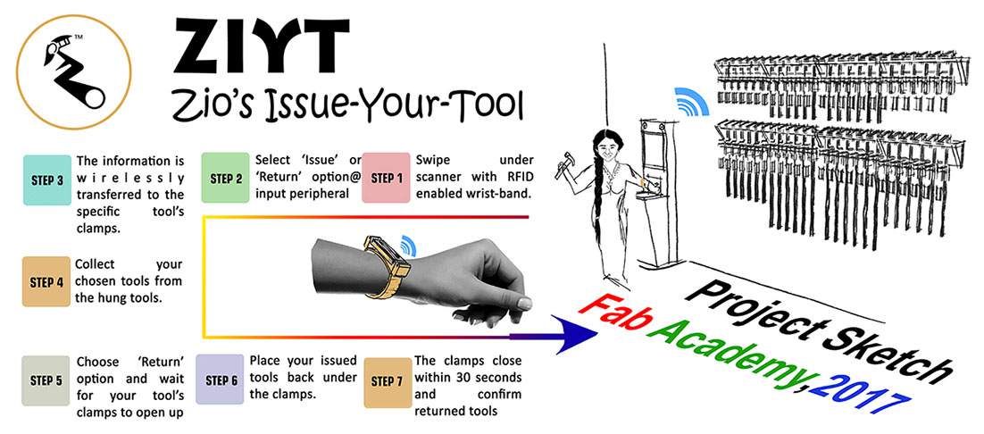
My project is called "Issue your tool"- its a tool managment system which is RFID enabled. So typically any person in a fablab/makerspace wears an wrist band which contains a rfid tag with an UID assigned to that person. In order to have him get issued a tool-he walks to a RFID scanner-scans his wrist-pick a tool and checkout by scanning again. On checking out-the Ir sensor of the tool holders changes LED status to red or green based on the absence or presence of the tool.
OBJECTIVE
To make a tool management system in a defined space but in a portable form which has Anti theft system and also user based authorisation , easy and quick to use, instant tool status updation and confirmation of your sign in and sign out.
BENEFITS
Helps in inventory management, which affects the labs monetarily and management wise.
Instant inventory counting
Lab can track the tool through the UID number.
In case any one tries to steal or move the tool without consent of the lab manager, the alarm will aware the Lab manager.
It will hold tools at one defined space making them accesible to everyone
Keeps the user informed about the availability of tools
REASON
I wanted to pursue a project which eases the inventory management, gives add on revenue model and is helpful for all the labs around the world having those tools which are core of our fabricating, prototyping hacks.
PROCESSES INVOLVED IN ZIYT
1. 3D Designing and 3D Printing
My project ZIYT involves, 3D designing of Tool holder, RFID wrist band.
I have used Software Sketchup for the same.
I tried making a complete product while designing. Designing has helped me bring my ideas to reality, being from nond esign background it was hard to learn new softwares , specially when every software has its own shortcuts and features.
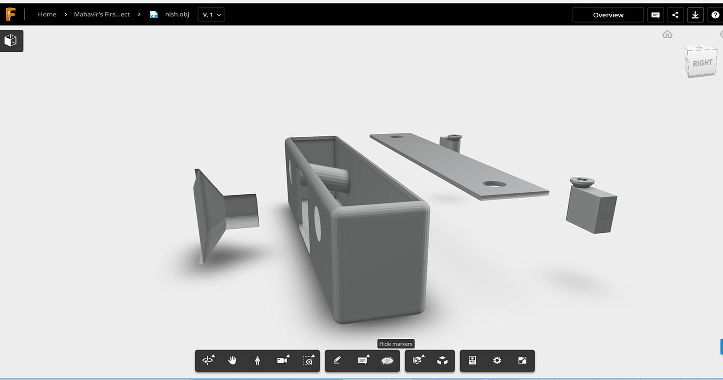
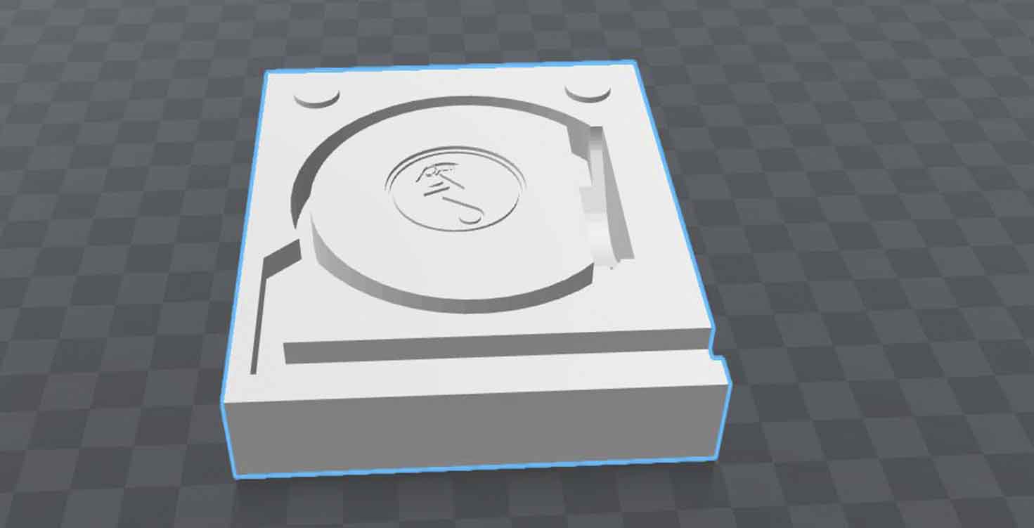
DESIGNING TOOL HOLDER
I am not from a Design background but due to my interest in designing and bring in small elemnts to increase the functionality of my design, i was able to do this.
Below is the rendered image of my design , which i did on Lumion. I agree with most of designers that rendering bring life to your product and its the most important step
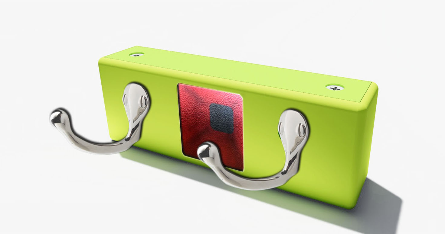
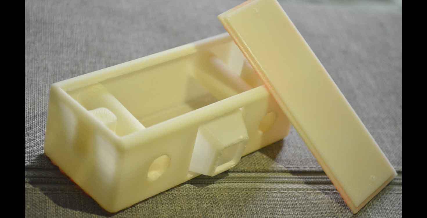
3d printing seems to be an easy process but it relies alot on your design and settings you do while creating gcode to g file.
While I used Repetier host and Kisslicer softwares, i was able to learn to control infill, support and support strength by the end of my project.
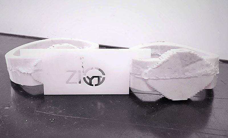
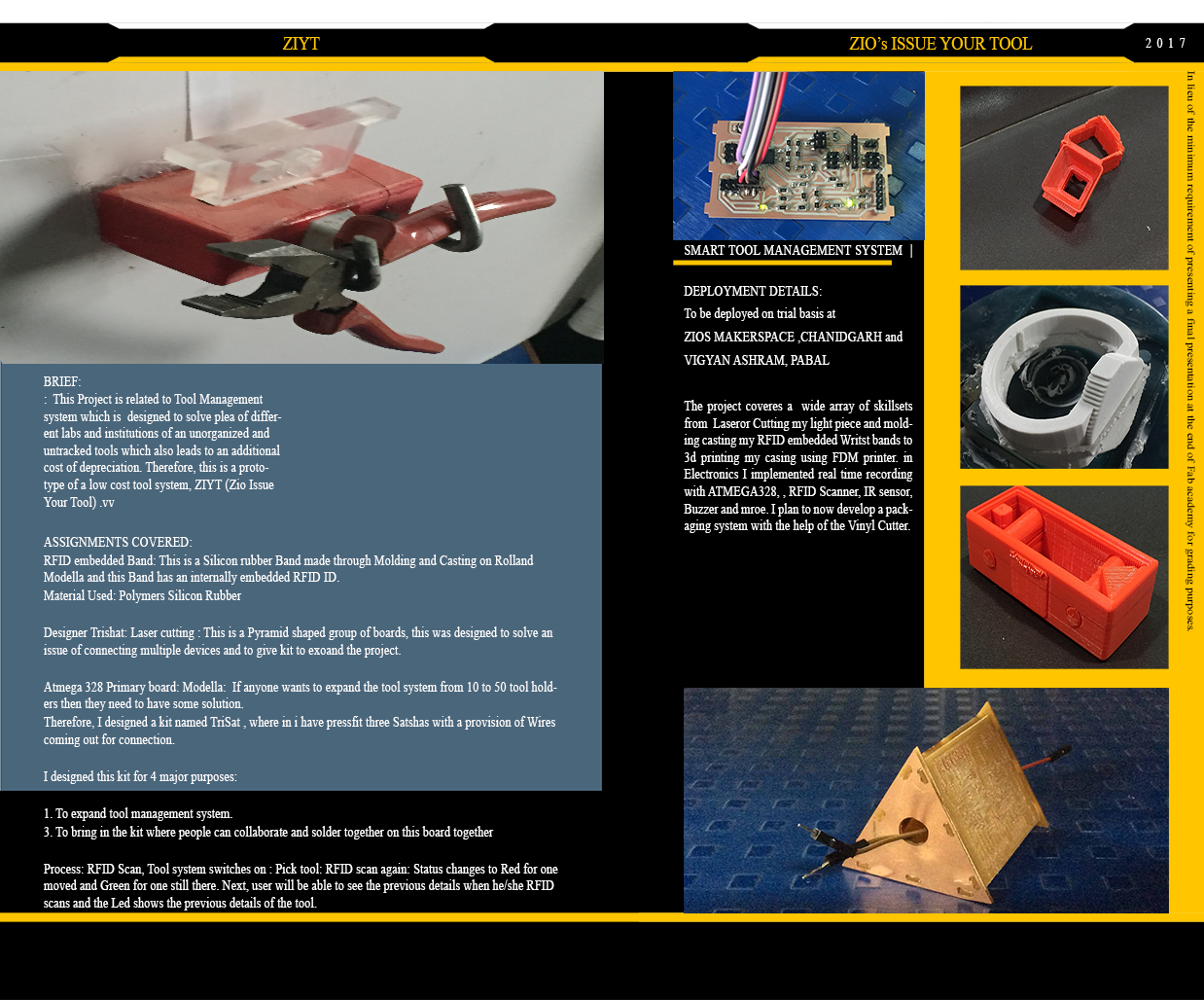
I printed a REd colour and a WHite color Tool Holder
3D Designing RFID band
Again, I designed my Wrist RFID band on Sketchup, this is the mold i prepared for the molding and casting week. I brought in some elements in my mold ike i made a slope and way for the solution to easy flow in my moould, I gave measured steps for my RFId tag to fit in well.
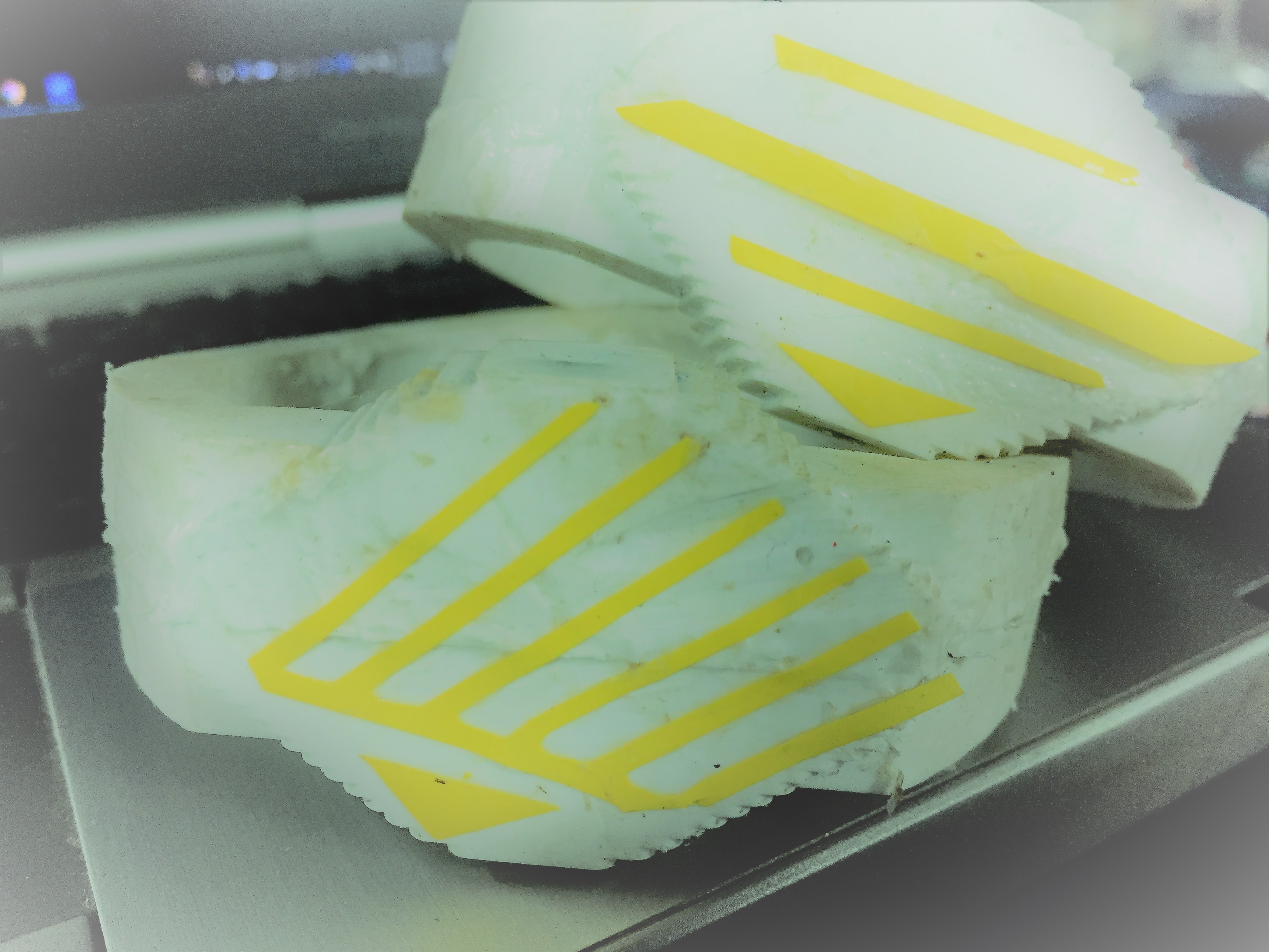
Molding and Casting for making RFID band
So for this process, i basically milled my wax mold on Rolland Modella and reused the wax for making my other wax molds by melting them , also i tried different processes of my mold with hydrostone, Rubber solution, Silicon rubber. and finally Silicon rubber was one of the best Material.
Below, i am testing the strength of RFID tag with different materials before embedding it.
After testing, milling, and putting Solicon rubber solution with prior measurements, vibration and removing bubbles.
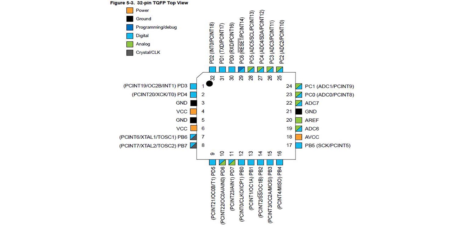
2. Electronics
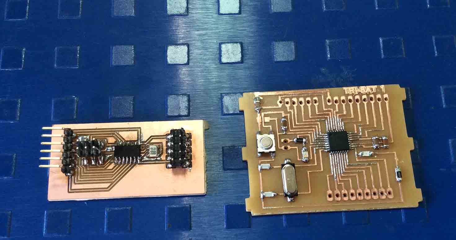
Electronics in this project plays a major role, starting from making an Attiny 44 board for my project to trying Satshakit and then finally after enough trials, making my own board ATMega 328.
ATTINY 44
PLAN A
This year, no one did Atmega 328 because it had'nt been tried before but our instructors were aware about its programming.
It started by designing the board by myself, Milling the board and then Bootloading it with the help of Arduino IDE.
First, i made Attiny 44 board for my project, in which i designed that it will have one IR and 2 LEDs.
This board will be connected to the mother board, but as suggested, i had to first make a proper prototype before aiming for 50 or 10 tools altogther. Therefore, i planned to make whole one board.
Trying Satshakit below,
Atmega 328 is my ideal board because i made lot of efforts to make it run,
Starting from Designing.
I started by writing down my requirements
This board has been designed to cover multiple devices but with Neil's suggestion i scoped down my project but kept code and design in a way that someone else is able to do it plus i am able to learn too.
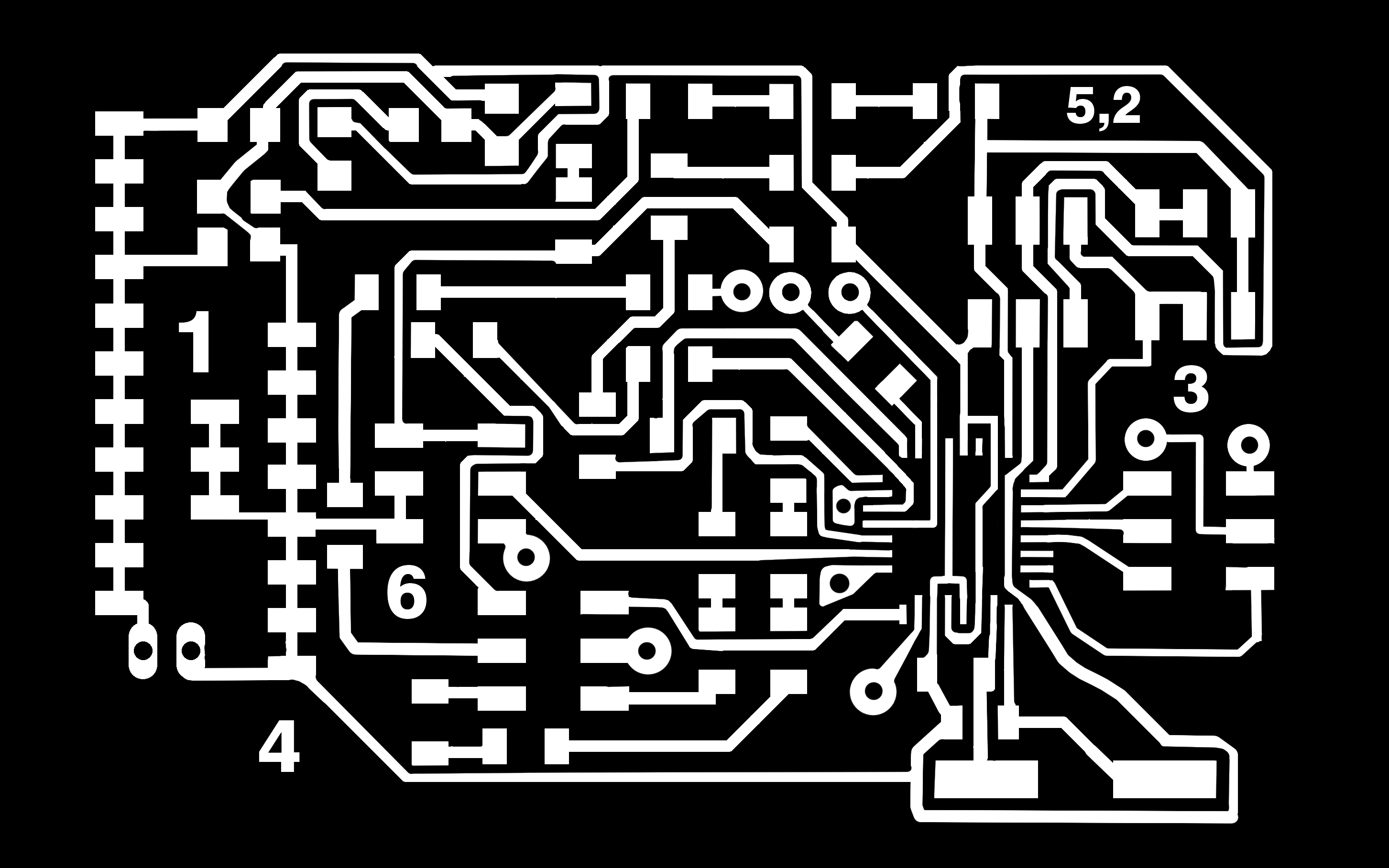
I designed my board the first time
Error Trace file:
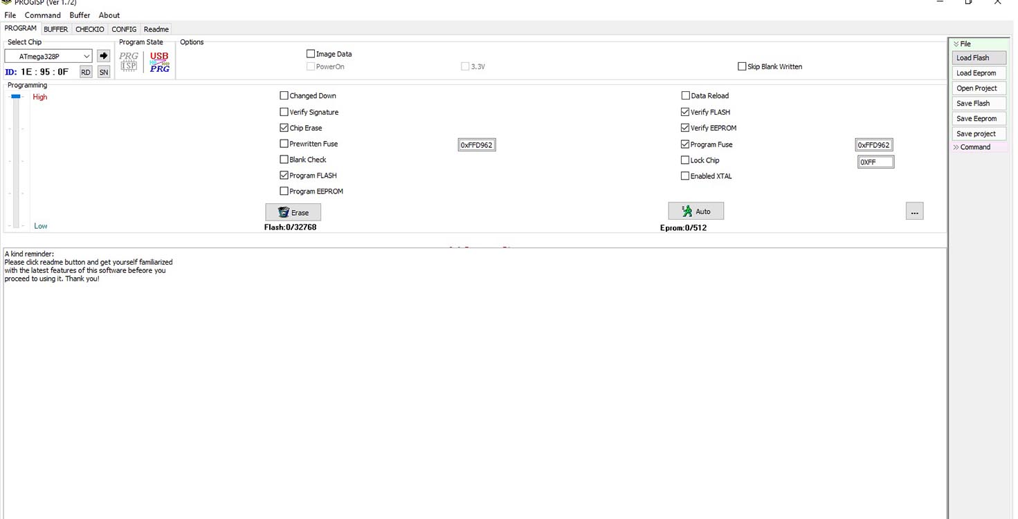
After milling, Soldering and while programming it with the help of PRogISP software and AVRISP of roboindia.com, it ran blink program but it failed to run my code.
So After a while, I noticed that my one LEd stopped even blinking after putting blink program again, so i soldered another LED and while soldering i realised some error in my board like i made few connections from backside the board which board was showing as faults in Autorouting. Plus i put lot of 0 ohm resistors to jump my connections as they were not Autorouting.
After hours of Trying, i almost gave up but I knew how much efforts i put in this board and my instructor suggested to check all connections , while sharing my schematic with him i noticed that I connected RFID specified pins to wrong Pins of the ATMEga 328
Few images of me trying Auto-routing.
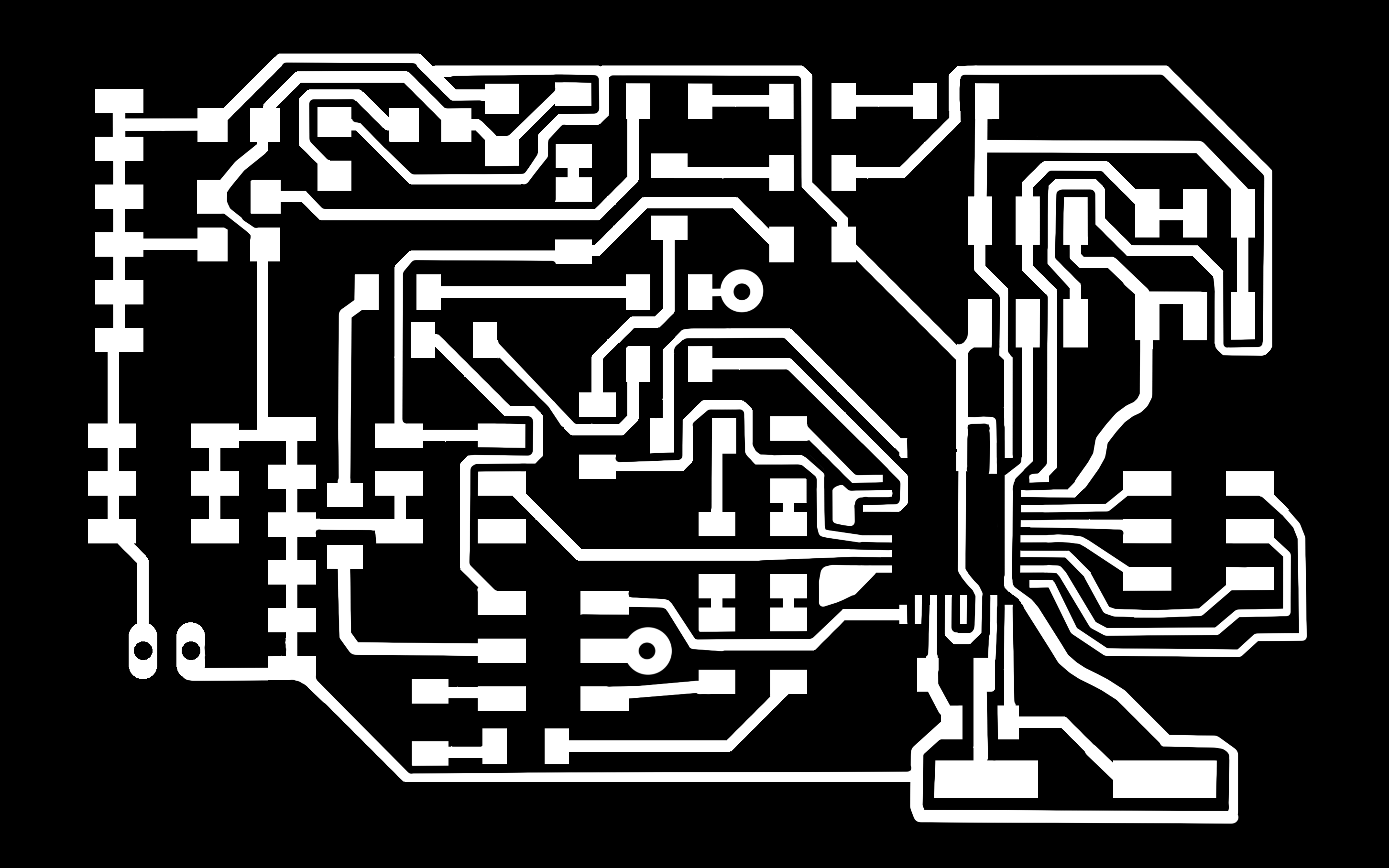
So i made another board, reused components, except crystal and leds.
My new trace file:
Milling my board with Milling bits 1.64 and 1.32 with the help of offline fab module-Rolland Modella-Png
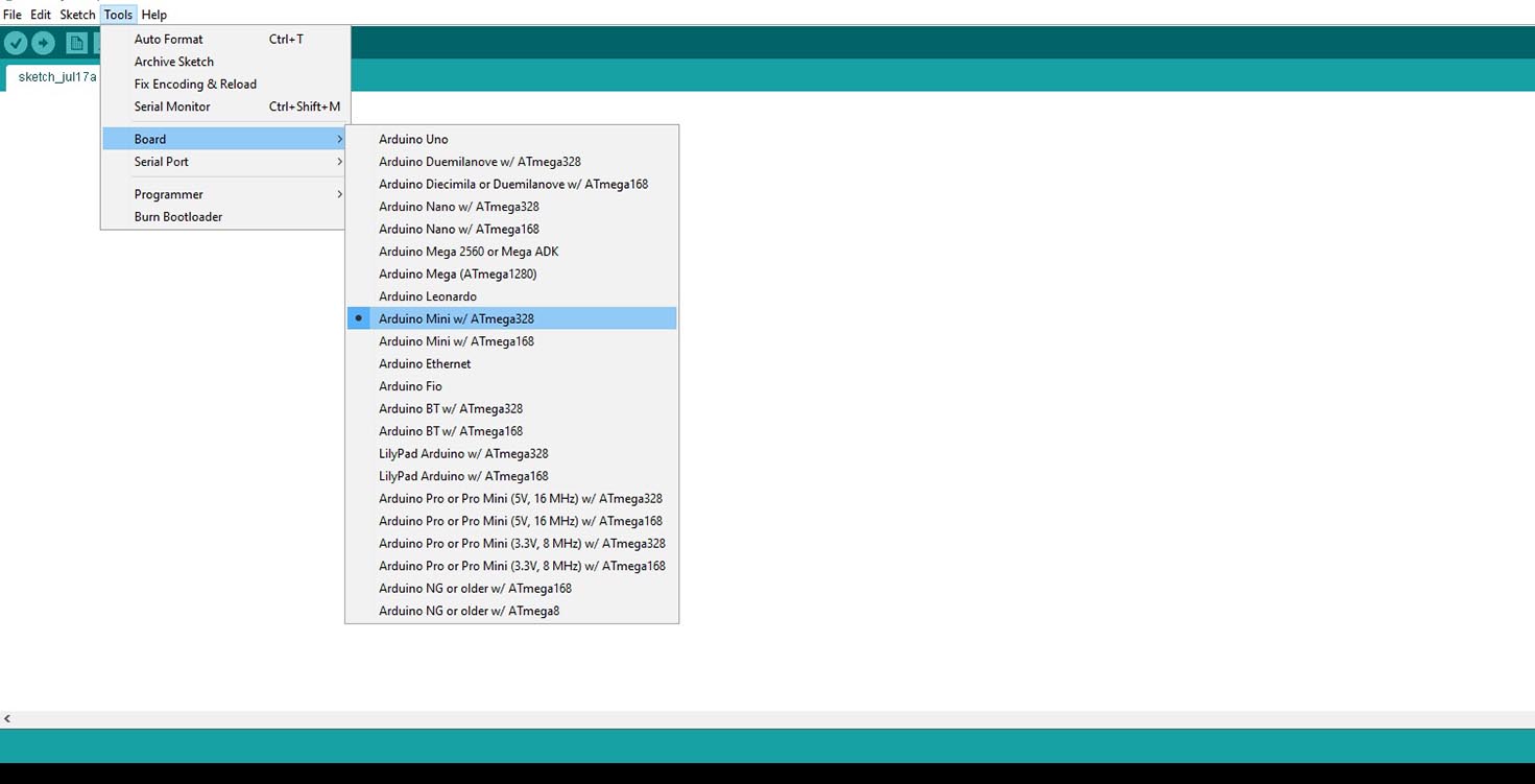
Then I used Arduino IDE to bootload my board.
I installed old version of Arduino IDE i.e arduino-1.0.1
It has provision for Atmega 328 unline the new ones in which i tried all board bt it didnt bootload
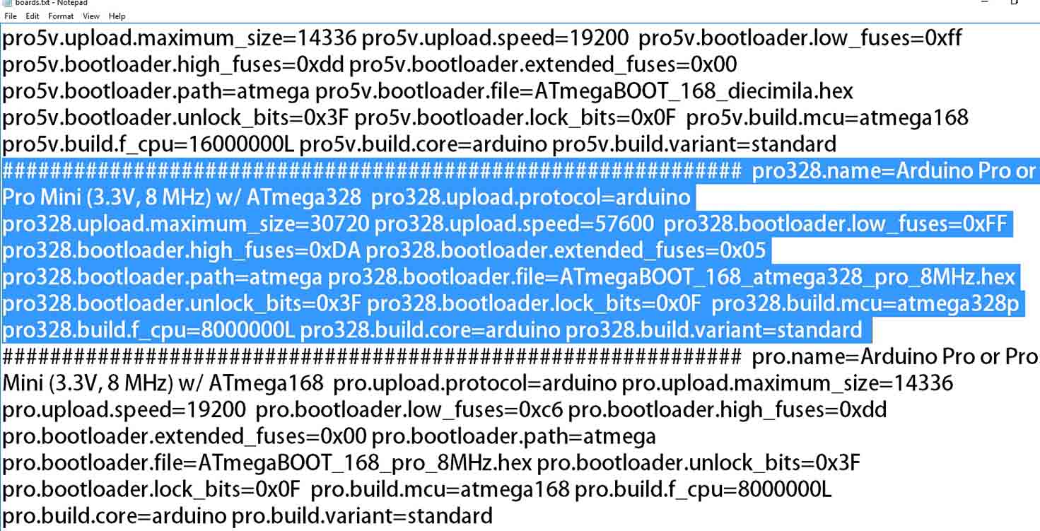
I opened Arduino folder>Hardware>boards and pasted the information below
and now when i open arduino 1.0.1 i can see the board option and bootload.
But issue now was , this version didnt had the drivers needed for RFId and other devices.
So i installed them and It was done.
So after this, i made connections according to this diagram
So i couldnt do changes in
In this , i refered this particular diagram
So After researching online, I ran my code on Arduino, as suggested by Instructor i ran same code with same pins on atmega 328, referiing above image.
It worked on Arduino, so it should run on Atmega 328 too.
Worked on Arduino:
So i ran it on Atmega
Final CODE:
I have made RTC and SD card as comment in this code
   * Typical pin layout used:
 * -----------------------------------------------------------------------------------------
 *             MFRC522      Arduino       Arduino   Arduino    Arduino          Arduino
 *             Reader/PCD   Uno/101       Mega      Nano v3    Leonardo/Micro   Pro Micro
 * Signal      Pin          Pin           Pin       Pin        Pin              Pin
 * -----------------------------------------------------------------------------------------
 * RST/Reset   RST          9             5         D9         RESET/ICSP-5     RST
 * SPI SS      SDA(SS)      10            53        D10        10               10
 * SPI MOSI    MOSI         11 / ICSP-4   51        D11        ICSP-4           16
 * SPI MISO    MISO         12 / ICSP-1   50        D12        ICSP-1           14
 * SPI SCK     SCK          13 / ICSP-3   52        D13        ICSP-3           15
 */

#include
#include
#include "RTClib.h"
#include

#define  RST_PIN  9    // Configurable, see typical pin layout above
#define  SS_PIN   10    // Configurable, see typical pin layout above

MFRC522 rfid(SS_PIN, RST_PIN); // Instance of the class

MFRC522::MIFARE_Key key;

RTC_DS1307 RTC;

char daysOfTheWeek[7][12] = {"SUN", "MON", "TUE", "WED", "THU", "FRI", "SAT"};

int ir1 = 0;
int ir2 = 1;

int buzzer = 7;  // speaker or buzzer on pin 8
int led_pos1 = 4; // green LED on pin 7
int led_neg1 = 5; // red LED on pin 6

int led_pos2 = 3; // green LED on pin 1
int led_neg2 = 8; // red LED on pin 2

String UID_tagA = "16025282126";  // UID of tag that we are using
String UID_tagB = "24094194128";  // UID of tag that we are using

short UIDs_No = 1;
short UID_No = 2;

// Init array that will store new NUID
int nuidPICC[4];
String readTag = "";

// Declaration of the functions
int getID ();
boolean checkTag();  // check if tag is unknown
//void StoreData();  // store data to microSD
void irsensor(); // detect first tool is present or not
void timing();

void setup() {
  Serial.begin(9600);
  SPI.begin(); // Init SPI bus
  rfid.PCD_Init(); // Init MFRC522
  Wire.begin();
  RTC.begin ();
   if (! RTC.isrunning()) {
    Serial.println("RTC is NOT running!");
    // following line sets the RTC to the date & time this sketch was compiled
    RTC.adjust(DateTime(__DATE__, __TIME__));
   }

  pinMode (0, INPUT);
  pinMode(1, INPUT);

  pinMode(led_pos1, OUTPUT);
  pinMode(led_neg1, OUTPUT);

  pinMode(led_pos2, OUTPUT);
  pinMode(led_neg2, OUTPUT);
  pinMode(buzzer, OUTPUT);
}

void loop()
{
 int succesRead = getID(); // read RFID tag
 if(succesRead == 1) // if RFID read was succesful
  {
      timing ();

       if (checkTag()) // if tag is known, store data
       {
          Serial.println("Known Tag");
          Serial.println("");
          irsensor();
       }

       else if (!checkTag())
       {
          Serial.println(" Unknown Tag");

           digitalWrite(7, HIGH);
           delay (10000);
           digitalWrite(7, LOW);
       }
     }
  }


// FUNCTIONS
void irsensor()
{
  int sensorValue = digitalRead(0);
      int sensorValue1 = digitalRead(1);
      if(sensorValue ==1 && sensorValue1 ==1 )
        {
          // print out the value you read:
            Serial.println ("Tools Taken");
            timing ();
            Serial.print("1st Tool - ");
            Serial.print(sensorValue);
            Serial.print("   ");
            Serial.print("2nd Tool - ");
            Serial.print(sensorValue1);
            Serial.println("\n");
           // delay(10);        // delay in between reads for stability
            digitalWrite(4, HIGH);
            digitalWrite(3, HIGH);
            digitalWrite(5, LOW);
            digitalWrite(8, LOW);
            timing ();
        }
     else if (sensorValue != 1 && sensorValue1 == 1)
        {
            Serial.println ("Tools Taken ");
            //timing ();
            Serial.print("1st Tool - ");
            Serial.print(sensorValue);
            Serial.print("   ");
            Serial.print("2nd Tool - ");
            Serial.print(sensorValue1);
            Serial.println("\n");

            digitalWrite(5, HIGH);
            digitalWrite(8, LOW);
             digitalWrite(4, LOW);
             digitalWrite(3, HIGH);
             timing();

        }
       else if (sensorValue == 1 && sensorValue1 != 1)
        {
            Serial.println ("Tools Taken");
            timing ();
            Serial.print("1st Tool - ");
            Serial.print(sensorValue);
            Serial.print("   ");
            Serial.print("2nd Tool - ");
            Serial.print(sensorValue1);
            Serial.println("\n");

            digitalWrite(5, LOW);
            digitalWrite(8, HIGH);
             digitalWrite(4, HIGH);
             digitalWrite(3, LOW);
                timing();

        }
       else if (sensorValue == 0 && sensorValue1 == 0)
        {
            Serial.println ("Tools Taken");
            timing ();
            Serial.print("1st Tool - ");
            Serial.print(sensorValue);
            Serial.print("   ");
            Serial.print("2nd Tool - ");
            Serial.print(sensorValue1);
            Serial.println("\n");

            digitalWrite(5, HIGH);
            digitalWrite(8, HIGH);
             digitalWrite(4, LOW);
             digitalWrite(3, LOW);
                timing();

        }

 }

boolean checkTag() // check if tag is unknown
 {
    if(readTag == UID_tagA){UIDs_No = 1; return true;}
    else if(readTag == UID_tagB){UIDs_No = 2; return true;}
    else {return false;}
 }

int getID()
{
  // Look for new cards
  if ( ! rfid.PICC_IsNewCardPresent())
    return 0;

  // Verify if the NUID has been readed
  if ( ! rfid.PICC_ReadCardSerial())
    return 0;

  readTag = "";
    // Store NUID into nuidPICC array
    for (int i = 0; i < 4; i++) {
      nuidPICC[i] = rfid.uid.uidByte[i];
       readTag = readTag+String(nuidPICC[i],DEC);
    }
     Serial.print("UID Tag NO : ");
     Serial.print(readTag);
     Serial.println(" ");

  // Halt PICC
  rfid.PICC_HaltA();
  return 1;

  /*// Stop encryption on PCD
  rfid.PCD_StopCrypto1();*/

}

void timing ()
{
  DateTime now = RTC.now();
  Serial.print(now.day(), DEC);
  Serial.print("-");
  Serial.print(now.month(), DEC);
  Serial.print("-");
  Serial.print(now.year(), DEC);
  Serial.print(" ");
  //Serial.print(daysOfTheWeek[now.daysOfTheWeek()]);
  Serial.print(" ");
  Serial.print(now.hour(), DEC);
  Serial.print(":");
  Serial.print(now.minute(), DEC);
  Serial.print(":");
  Serial.println(now.second(), DEC);
  delay(1000);

}
This board was another troublesome because while routing this one, i had put so many 0 ohm resistors to cross connect and auto route the same.
But then this time i read each and every line of the Datasheet of Pin configurations and then made this board
You can find it here DATASHEET
I made board reading datasheet, but later made connections according to the conenctions made on Arduino and above diagram but it all started fitting well.
By this time, it been 48 hours of continous work and i almost gave up.
But then looking at my Trishat kit , it gave me inspiration to complete it
My trials while working on my board
I shortened my code
TRIAL 1
TRIAL 2
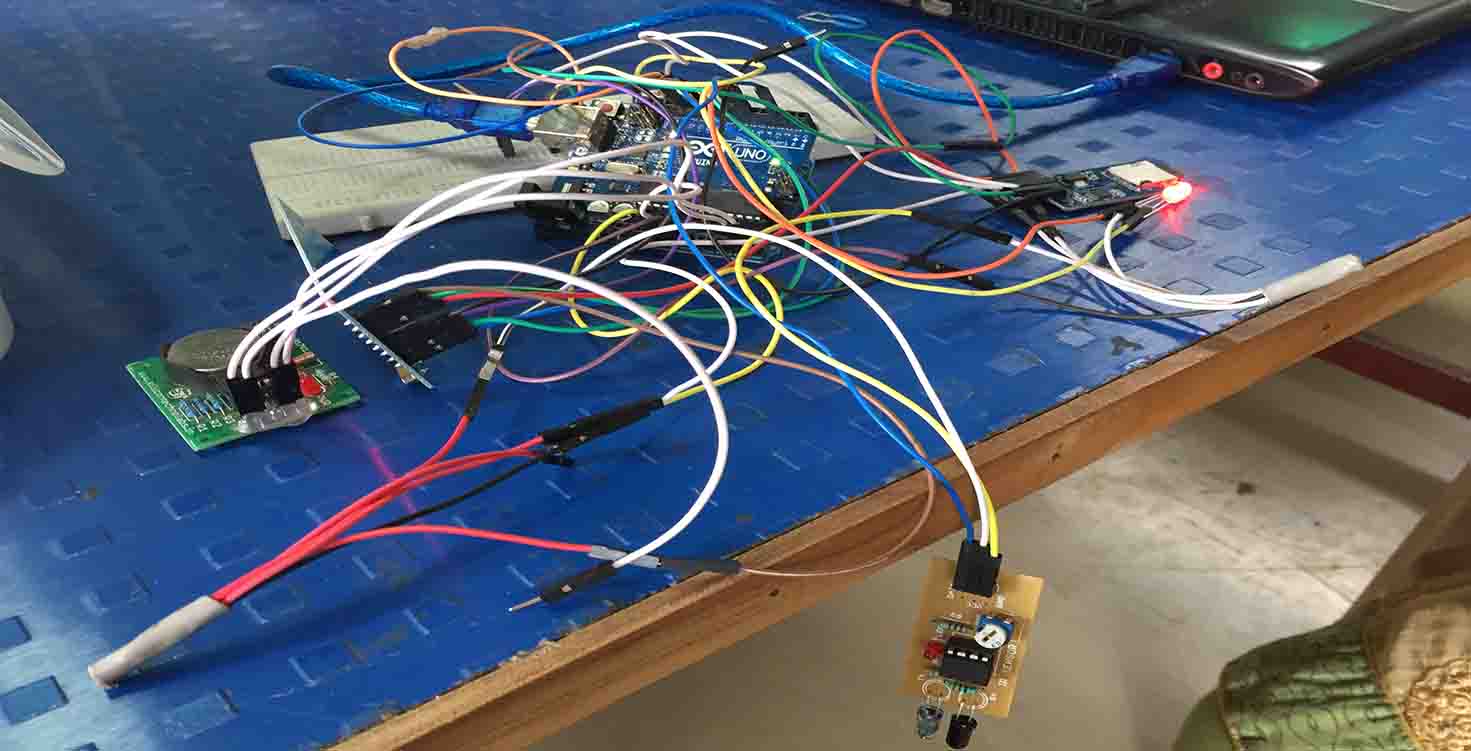
Even after making board right, code right and i was unable to make my whole thing work altogether but then i prefered checking my wires so i took 40 wires , checked them all and used them for my project throughout
ATMEGA running
Final Video with authorised Band and Unauthorised band
SO the Final video is that, a user comes, Picks his tool, Scans his RFID band and status of the tool changes due to IR.
TRISHAT KIT
Purpose of this kit:
I started with an idea of making a system for 10-50 tools, when i planned for it, i proposed a plan of having a mother board which would be satshakit or my own designed board
and that mother board will connect with middle board, so to assemble them all together i designed trishat pressfit, but when i changed few plans so that i am able to achieve in the given duration, I used it for connecting my RFID with buzzer embedded inside it and for my main board atmega 328
Laser cutting
I cut a pressfit logo and project name plate in which i made it of exact dimensions of my tool holder lower base., it also had engraving of my project on it.
The purpose of it was to show project name as well as help LED glow
Vinyl Cutting
Loading Pattern file i made on Offline fab module
Setting up the sheet
setting power and speed of the vinyl cutter
Future Scope
I didnt had much time to do this on my board because i was confused with two slaves sharing same PINS problem, for RFID and SD card.
Plus neil told me that data saving can be done later.
I still managed to this till the end
I made a code for having RTC (for recording time) and SD card (for saving data)
I made provision for the same in atmgea 328 board
I was able to run all this with borrowed devices on arduino
The days of a pile of equipment lying on the floor or kept in a locked cupboard are long gone, replaced by a a small , handy, smart and universally adapatable , low cost ZIYT Tool Holder.