Project
Diagram
Description
Main objetive:
Develop Scratch® compatible set of devices, that can be used for pedagogical, artistic or leisure purposes, with sensor and actuators that the user manipulate without previous electronic or programing knowledge.
Specific objetives:
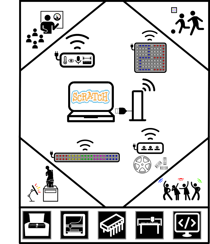
- Build a control device, that receive data from external sensors and send instructions to external actuators using Bluetooth, this device will communicate with Scratch through a USB cable.
- Develop a Scratch extention, with the necesary command boxes to manipulate or receive data from the control device.

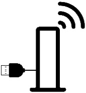
- Elaborate a device that allows to measure and communicate the temperature, light level, ambient sound and proximity, whose power supply comes from an external source.
- Construct an actuator device of rectangular and elongated shape, with a matrix of 20 columns x 2 rows of neopixels, with all necesary libraries to control them and whose power supply is external.
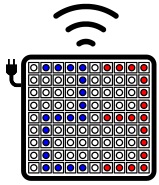
- Construct an actuator device of square shape, with a matrix of 10 columns x 10 rows of neopixels, with all necesary libraries to control them and whose power supply is external.
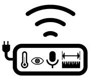
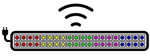
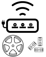
- Build an device with 3 holes corresponding to 5 volts, ground and data, where will be connect the three cables of a neopixel strip, with a maximum of 100, with all necesary libraries to control them and whose power supply is external..
Justification
Scratch offers the possibility to work on a computer, but does not allow interact with the environment. That is why have been developing different gadgets, which through a USB connection, offer the possibility to read some types of sensors and activate-deactivate different actuators. Currently, Scratch allows the evolution of the program so that new functionality can be incorporated (Dasgupta, Clements, Idlbi, Willis-Ford, & Resnick, 2015). This opens the door to the development of wireless systems integrating Scratch with different sensors and actuators (Idlbi, 2014).
From a pedagogical point of view, a solution of this type and that use open technologies would undoubtedly be a great educational resource that could help many people to acquire what is now known as computational competence (Barr, Harrison, & Conery , 2011).
From other areas of usability, such as art, architecture, music, dance or leisure, having a quick communication device with Scratch, will allow at the user, for example, to create custom lighting with effects and transitions which he himself will be able to program, and operate with the computer keyboard, or that they automatically react to data provided by temperature, light, sound or proximity sensors.
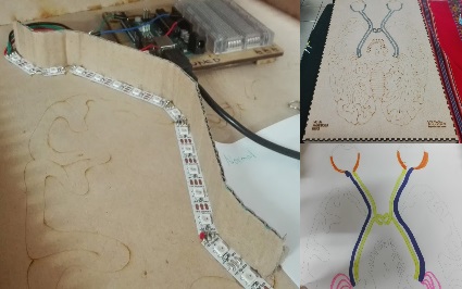
For example, this is a current need to implement the project. It consists of a simulator of optic nerve abnormalities, which will be used for students of a psychology course at the University of Costa Rica, as a way to understand the functioning of the human brain. If the partners working on the project (Alicia and Esteban) had a device that can control the neopixeles from Scratch, they would not depend on me to do the programming.
References: 1) Ananiadou, K., & Claro, M. (2009). 21st Century Skills and Competences for New Millennium Learners in OECD Countries. OECD Education Working Papers, 41. https://doi.org/http://dx.doi.org/10.1787/218525261154 2) Barr, D., Harrison, J., & Conery, L. (2011). Computational Thinking: A Digital Age Skill for Everyone. Learning & Leading with Technology, 38(6), 20-23. 3) Dasgupta, S., Clements, S. M., Idlbi, A. Y., Willis-Ford, C., & Resnick, M. (2015). Extending Scratch: New pathways into programming (pp. 165-169). IEEE. https://doi.org/10.1109/VLHCC.2015.7357212 4) Idlbi, A. Y. (2014). Personalized extensions : democratizing the programming of virtual-physical interactions (Thesis). Massachusetts Institute of Technology. Recovery from http://dspace.mit.edu/handle/1721.1/95605 5) Kafai, Y., & Resnick, M. (1996). Constructionism in practice: Designing, thinking, and learning in a digital world. New Jersey: Erlbaum Associates. 6) Papert, S. (1993). The children’s machine: rethinking school in the age of the computer. New York: BasicBooks. 7) Papert, S. (1997). La familia conectada: padres, hijos y computadoras. Buenos Aires: Emecé. 8) Papert, S. (2005). Teaching Children Thinking. Contemporary Issues in Technology and Teacher Education, 5(3), 353-365. 9) Resnick, M., Silverman, B., Kafai, Y., Maloney, J., Monroy-Hernández, A., Rusk, N., … Silver, J. (2009). Scratch: programming for all. 10) Communications of the ACM, 52(11), 60. https://doi.org/10.1145/1592761.1592779 11) Rusk, N., Resnick, M., & Maloney, J. (2010). Learning with Scratch 21st century learning skills. Recovery from llk.media.mit.edu/projects/scratch/papers/Scratch-21stCenturySkills.pdf
Development
Objetive:
Show how the final project was developedLinks:
MakerCase Neopixel stripResources:
STL brackets for 3D printing (Device 1) PDF case for laser cut (Device 1) INO RxTx Serial board code (Device 1) INO Tx board code (Device 1) INO Rx board code (Device 1) BRD Eagle board design TxRx Serial (Device 1) SCH Eagle schematic RxTx Serial (Device 1) BRD Eagle board design Tx (Device 1) SCH Eagle schematic Tx (Device 1) BRD Eagle board design Rx (Device 1) SCH Eagle schematic Rx (Device 1) PDE Processing interfase (Device 2) INO FABduino code (Device 2) 3DM Rhino (Device 2) PDF Acrilic cover (Device 2) STL Case for neopixels strip handler (Device 3) INO Rx board code (Device 3) INO Tx board code (Device 3) BRD Eagle board design Rx (Device 3) SCH Eagle schematic Rx (Device 3) BRD Eagle board design Tx (Device 3) SCH Eagle schematic Tx (Device 3)
Project scope
For reasons of time not all the proposed project was developed. Of the 5 proposed devices only 3 were made, however they are the most important. Also the integration with Scratch was not made and only temporarily an interface was made with Processing
First device
The first device is the communicator, whose job is to receive instructions from the interface made in Processing through the serial port and forward it to the other devices using radio frequency communication
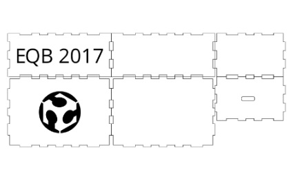
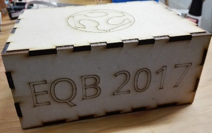
Simple case
For this device I used the online tool MakerCase to design a simple rectangular box and cut it with the laser cutter

Cutting process
Here we can see the cutting process using the machine RedSail CM1690
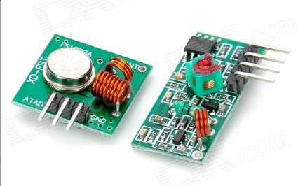
External modules
RF 433 Mhz modules will be used for wireless communication. These modules were used in the networking and communications assigment
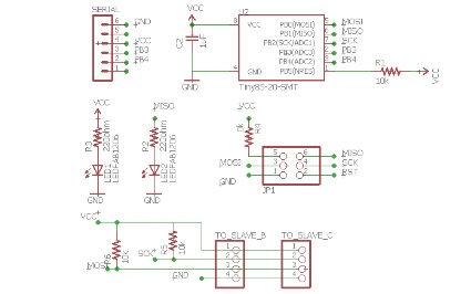
Circuit A
The first circuit has a serial connection to the computer using the TTL Serial Cable, used in input devices assigment, it is also the master that communicates through the standard I2C with the 2 slave circuits that are also part of the device. The slave B is the one who sends the instructions through RF and the slave C is the one who would receive values from the device with sensors (that was not developed for this project)

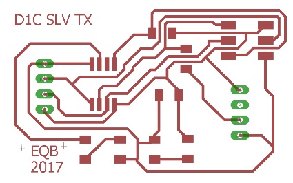
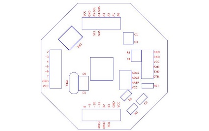
Circuit A board
This is the design of circuit board A made in Eagle

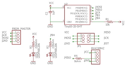
Circuit B
Circuit B (Tx) receives the instruction via I2C from circuit A and relays it through the RF433Mhz module

Circuit B design
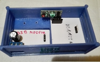
In the design of the circuit B there are 3 holes for the female pinheaders, here we will put the 3 pins of the transmitter module RF433Mhz
Circuit C
Circuit C (which was made but not used in the project) is the receiver of data that would arrive from the device with sensors
Circuit C design
Circuit C has a design similar to B, the only difference is that it has 4 female pinheaders for the RF433Mhz receiver module

3d printed brackets
To support the boards inside the box, I designed and printed 3D brackets and I fixed them with fast drying glue
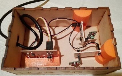
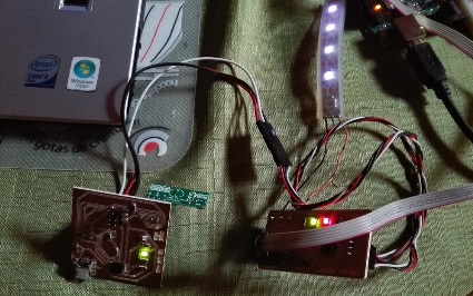
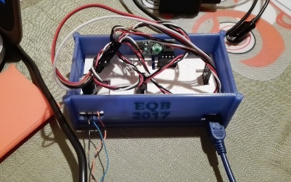
Inside the box
This shows the device 1 finally assembled

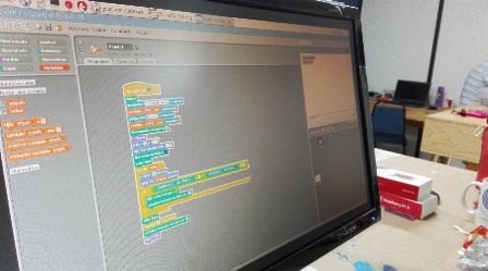
Interface made in Processing
The original idea of my project was that the system interface was Scratch, however for reasons of time I developed a simple screen in Processing

Simple interaction
The screen allows to select the color, the type of effect (previously programmed 5) and the device (color matrix or neopixeles handler)
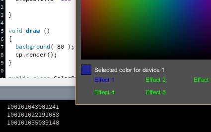
Serial communication
Each time you click on a color, or on an effect or device, text is sent through the serial port
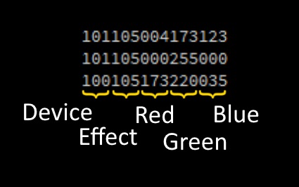
Instruccion code
The code consists of 5 segments of 3 digits corresponding to: Device 1 (100), Device 2 (101), Light effect to be executed (101-105), color red (0-255), green color (0-255 ), Blue (0-255)
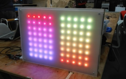
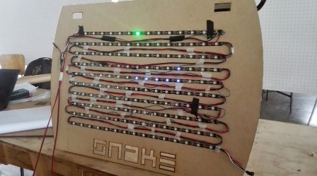
Device 2
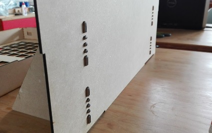
The device 2 is a matrix of neopixels with 2 segments of 8x5. The goal is to display letters, numbers and create effects
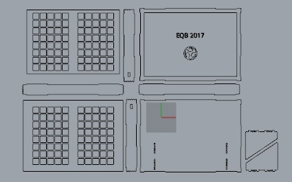
Design in Rhino
The design for laser cutting was done in Rhino

Adafruit NeoPixel LED Strip
As the main element of this device, I used the Adafruit NeoPixel LED Strip. Each meter has about 60 neopixeles. Requires the use of a 1000 1µF capacitor which as will be seen later is already included in the circuit
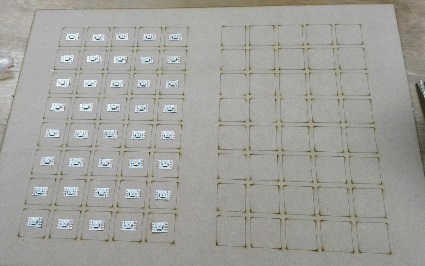
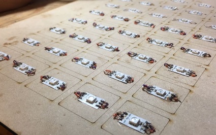
Cut and paste
I literally had to cut and paste neopixels, one by one putting them in the center of the laser-made marks

Drilling the holes
Easily drilled holes using a wood drill in the milling
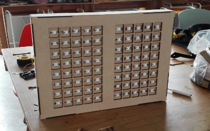
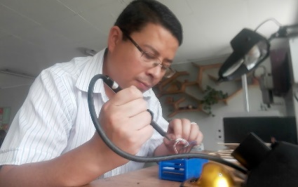
Soldering joints
Soldering joints was not an easy job, I needed almost 3 full days to do it
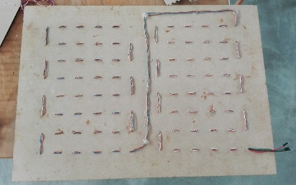
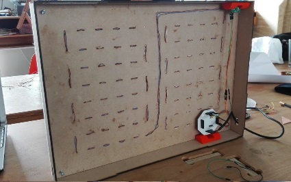
Back view
It may not be the best of my jobs but the important thing is that it works

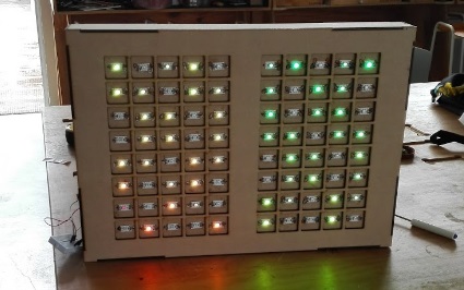
Ready for test
Once all the soldering is finished, I can now do the first integral test, on the way I had tried row by row but it is time to test everything
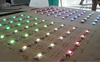
First test OK
The test looks great. All the lights come on and I can adjust the brightness

Assembling the cover
I can continue to assemble the cover, the design allows me to assemble it and in the end to place the light panel

Fabduino
The original idea was to develop a pair of circuits that would work the same as device 3, however for reasons of time I made the Fabduino, whose design was developed by comrade Juan Carlos Miranda
Nice design
The design made by Juan Carlos is very practical since it facilitated the welding process. Juan Carlos also designed a cover with the names of the pins
Putting it all together
It is time to install the electronics of the device. To hold the boards I used pieces printed in 3D with the same design of the previous device
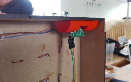
RF433 receiver module
I put the RF433 receiver module on top for better data reception

Rear supports
The rear supports mantains the device in vertical position
Press fit
The supports are held in place thanks to the press fit design
Placing the light panel
As the rest of the deck is assembled, I can put the lights panel
Another test
I run another test to check that all the lights are fine
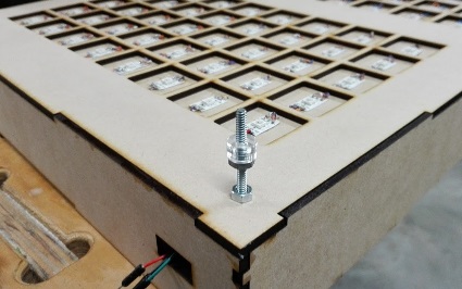
Front panel screws
To fix the milky white acrylic front panel, place 4 screws with nuts and small washers also cut in acrylic

Perfect fit
The holes in the acrylic fit perfectly and the finished product looks great
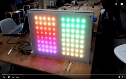
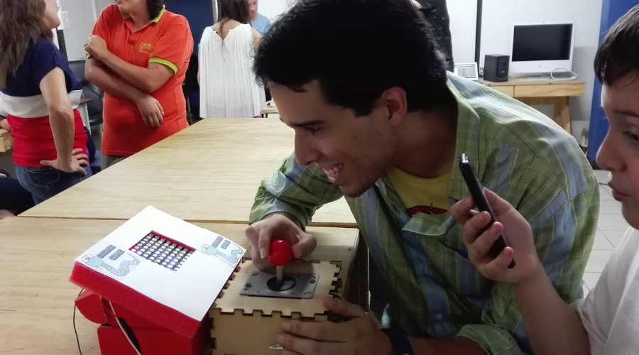
Demo video
Click on the image to see a video of the device in action

Demo video
Click on the image to see a video of the device in action
Device 3
The device 3 is neopixel strip controller, like the previous device, receives the instructions wirelessly, the difference being that the user can make their own customized installations of lights

How it works?
The device has 2 circuits, one as master and the other slave, the master expects to receive instructions through the RF433Mhz receiver module. When it receives an instruction it establishes a connection with the slave through the standard I2C and it sends him the instruction
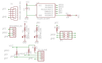
Circuit A
The slave executes the instruction on the neopixel strip with a maximum of 100. Uses an Attiny85 microprocessor.
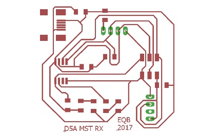
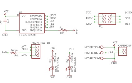
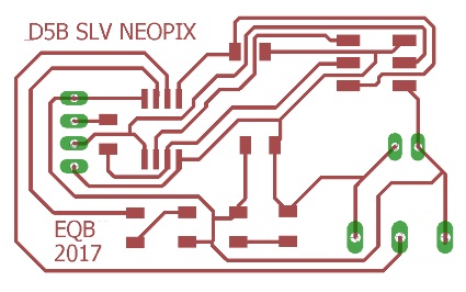
Circuit A design
It has 4 female pinheader for RF receiver and 4 pin for I2C communication (GND, VCC, SDA, SCK)
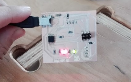
Independent power supply
Also it has a USB connector to power it, does not need any other external cable to operate
Circuit B
Circuit B acts as slave I2C, which receives the instruction from the master causing an interrupt and returns a 1 in response
Circuit B design
It has 2 spaces to connect the 1000 μF capacitor and a screw terminals pitch to connect the neopixel strip
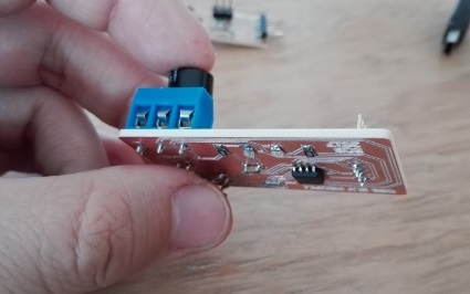
Screw terminals pitch
I put a screw terminals pitch to connect the neopixel strip
Testing the boards
I honestly did not know if I could get the microprocessor to function as an I2C slave and at the same time handle the neopixeles, but I did
Limitation
The limitation I found, is that I can only handle a maximum of 100 neopixeles
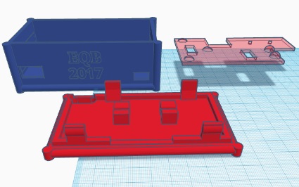
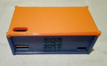
The cover
I designed the cover for 3D printing. To fix the boards I made a kind of plate that is fixed with screws
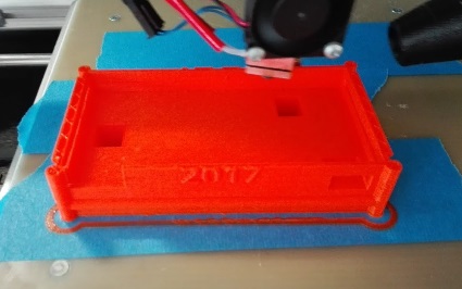
Printing process
Printing of the main piece took about 4 hours

Printing from the top
I printed the top in another color and took about an hour
A little tight
I need a little effort to put the board A and the B was a bit loose
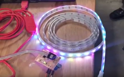
Test before screwing
I did a quick test before putting the cover with screws
Final settings
I reinforced the connector of the neopixeles a little and adjusted other minor details

New cables
I bought new cables for I2C communication and they do not look so bad
Demo video
Click on the image to see a video of the device in action
Powered by w3.css