Week 15: networking and communications
Experience: Using RF433MHZ
Objetive:
Implement and interpret networking protocolsLinks:
433MHz RF link kitResources:
INO Rx code INO Tx code BRD Eagle board design Rx SCH Eagle schematic Rx BRD Eagle board design Tx SCH Eagle schematic Tx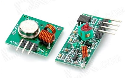
433MHz RF
I decided to use the 433 MHz RF module for the assignment because I am going to use it in final project. Technical details: 433MHz, 500ft range (given perfect conditions), 4800bps data rate, 5V supply voltage
2 boards with ATTINY85
I made 2 boards to use the TX and RX 433MHz RF module but also left the pins to make a connection with the L2C protocol
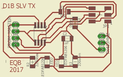
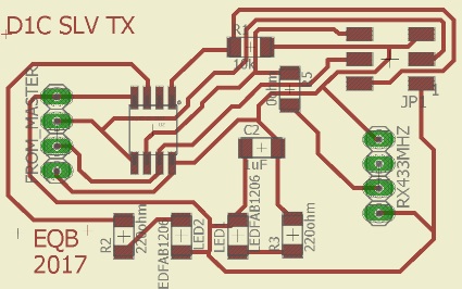
TX board diagram
I use an ATTINY85 microprocessor, 1 power LED, 1 led as transmission signal, resistors, capacitor, pins for programming, pins for L2C connection and pins for the 433MHz RF transmitter module
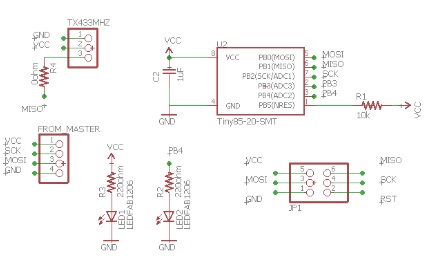
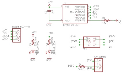
Schematic view
This is the schematic made in EAGLE and can be downloaded in the resources section
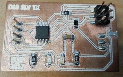
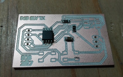
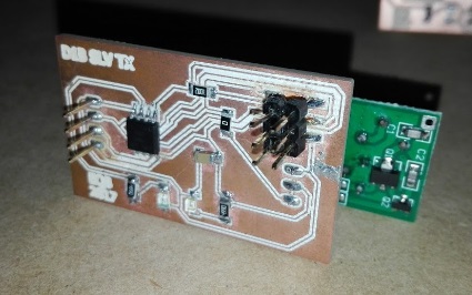
Board 1 completed
This is an image of how board 1 looks finished, accidentally spilled some tin on the right side and I could not remove it
RX board board
This is the diagram of the board 2, the only difference is that it has an additional pin because that way the RX module of the 433MHz RF
Schematic view
Iquals to the board 1, I use an ATTINY85 microprocessor, 1 power LED, 1 led as transmission signal, resistors, capacitor, pins for programming, pins for L2C connection and pins for the 433MHz RF receiver module
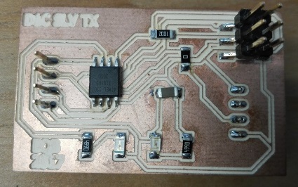
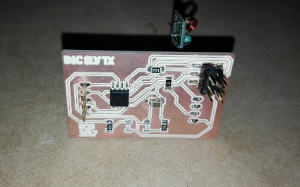
Board 2 completed
This is how board 2 is completed
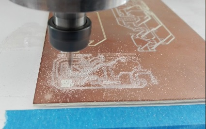
Cutting process
The cut was made in the CNC Kingcut KX4060
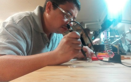
Soldering process
The soldering was done on thursday night at the Fab Lab Veritas
Slow and careful
In order not to stains with tin the board 2, I took the process of welding more slowly
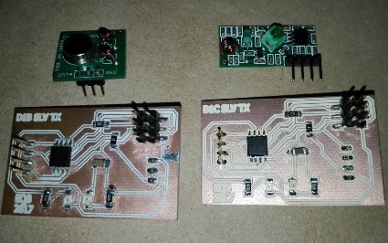
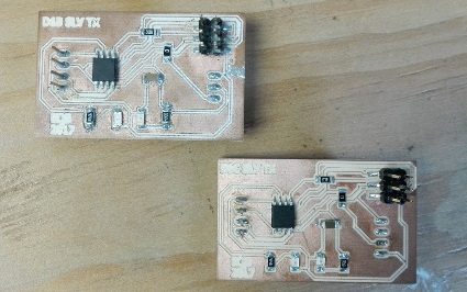
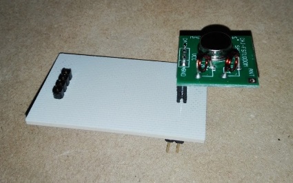
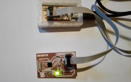
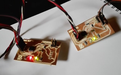
Modules and boards
Here we see the boards finished with their respective module before assembling
Tx front view
This shows the transmission module from the front
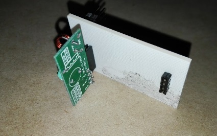
Tx back view
And so it looks from behind. I decided to put the female pins in the back so as not to remove the module every time I needed to program the board
Rx front view
This is the front view of the assembled receiving module
Rx back view
As with the previous module, the female pins are located at the rear, this was a last minute decision when soldering
Programing the boards
The final step was to program the cards. After many trial and error interactions, I was able to find the right parameters to establish the communication
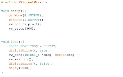
Tx code
This is the test code for the transmitter. Basically what it does is send a number and turn on a led every few seconds to indicate that it is transmitting
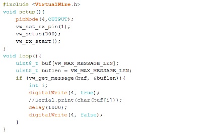
Rx code
This is the test code for the transmitter. In this case simply turn on a led every time you received the number sent by the transmitter
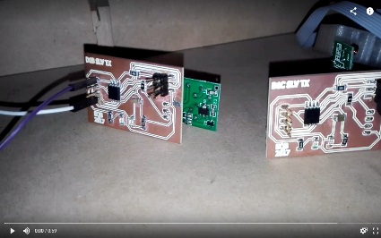
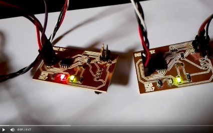
Demo video
Click on the image to see a video of the system in action
Experience: Using L2C protocol
Objetive:
Implement and interpret networking protocolsLinks:
I2C (master and slave) on the ATtiny85Resources:
INO master code INO slave code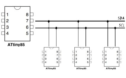
Using the L2C protocol
When I saw this diagram of the L2C communication I thought that I physically only needed to join the SDA and SCL pins and that the rest was done with programming
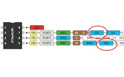
SDA and SCL pins
In this drawing we can see which pins correspond to SDA and SCL in an Attiny85
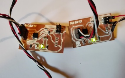
Big mistake
So my boards were ready to connect to each other, but it never worked
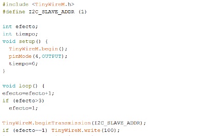
Tx code demo
It was assumed that the transmitter code would send 3 visual effects to be executed in the LED of the receiver
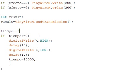
Tx code demo
And every few seconds he would turn on his own led to indicate that he was constantly transmitting
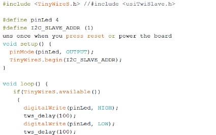
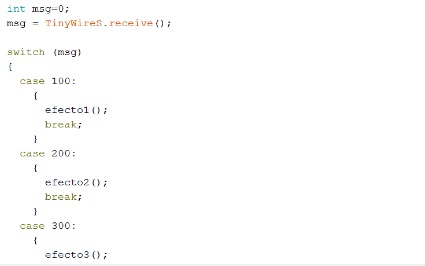
Rx code demo
On the other hand the receiver would take the order of the transmitter (one at a time) and execute the visual effect on the red led
Rx code demo
The effects were simple: fade slowly, blink 10 times fast and blink 2 times and wait. But communication never worked
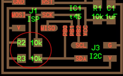
The solution
The solution was in the diagram shown by Neil where it is clearly seen that there must be a resistance of 10K between the pins and VCC
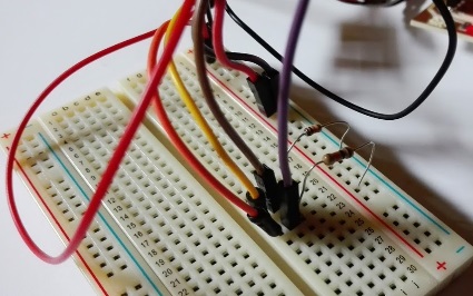
Testing the solution
So with the help of a breadboard I put the respective resistors that fortunately had at that moment
It worked !!!
After many hours of failed attempts and unsuccessful searches on the internet, the solution was always in front of my nose
Video demo
Click on the image to see a video of the system working
Powered by w3.css