


week 8
Embedded Programming.
Assignment:
* read a microcontroller data sheet
* program your board to do something, with as many different programming languages
and programming environments as possible. Extra credit: experiment with other architectures". . . "
* read a microcontroller data sheet
* program your board to do something, with as many different programming languages
and programming environments as possible. Extra credit: experiment with other architectures". . . "
Guillermo Jaramillo :: Fab Academy 2017
Fab Academy 2017

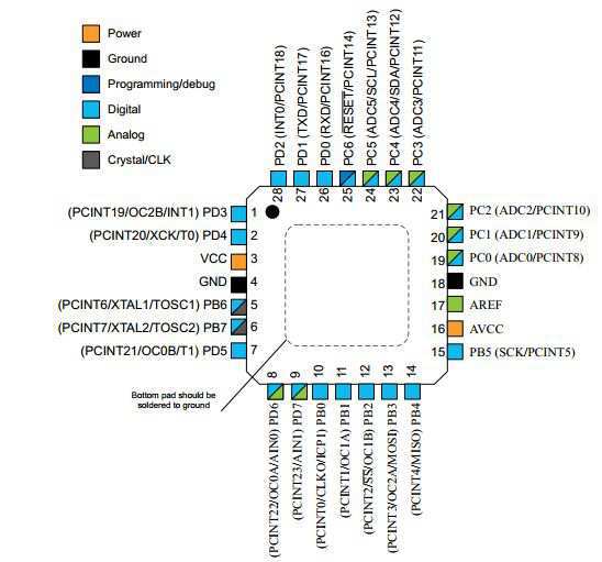
I start reading the documentation of Atmel AtMega328p. For my final project to modify a custom mode satshakit to be able to operate inputs and outputs as input and output sensors, so I am interested in programming the 328p. The datasheet of the microprocessor is avaliable clicking the image below.
So, the first step is to recognize the pinout of the processor and the correspondency with an arduino uno board.
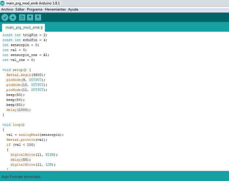
And now to test the software that operates the input sensors and the output ones was programmed using arduino IDE
const int trigPin = 2;
const int echoPin = 4;
int sensorpin = 0;
int val = 0;
int sensorpin_one = A1;
int val_one = 0;
void setup() {
Serial.begin(9600);
pinMode(9, OUTPUT);
pinMode(10, OUTPUT);
pinMode(11, OUTPUT);
beep(50);
beep(50);
beep(50);
delay(1000);
}
void loop()
{
val = analogRead(sensorpin);
Serial.println(val);
if (val < 100)
{
digitalWrite(11, HIGH);
delay(55);
digitalWrite(11, LOW);
}
delay(400);
val_one = analogRead(sensorpin_one);
Serial.println(val_one);
if (val_one > 700)
{
digitalWrite(10, HIGH);
}
else
{
digitalWrite(10, LOW);
}
long duration, cm;
pinMode(trigPin, OUTPUT);
digitalWrite(trigPin, LOW);
delayMicroseconds(2);
digitalWrite(trigPin, HIGH);
delayMicroseconds(10);
digitalWrite(trigPin, LOW);
pinMode(echoPin, INPUT);
duration = pulseIn(echoPin, HIGH);
cm = microsecondsToCentimeters(duration);
if (cm < 200)
{
beep(500);
beep(500);
beep(500);
}
delay(100);
}
long microsecondsToCentimeters(long microseconds)
{
return microseconds / 29 / 2;
}
void beep(unsigned char pausa)
{
analogWrite(9, 20);
delay(pausa);
analogWrite(9, 0);
delay(pausa);
}
Now i try to compact the code and probe the digital outputs:

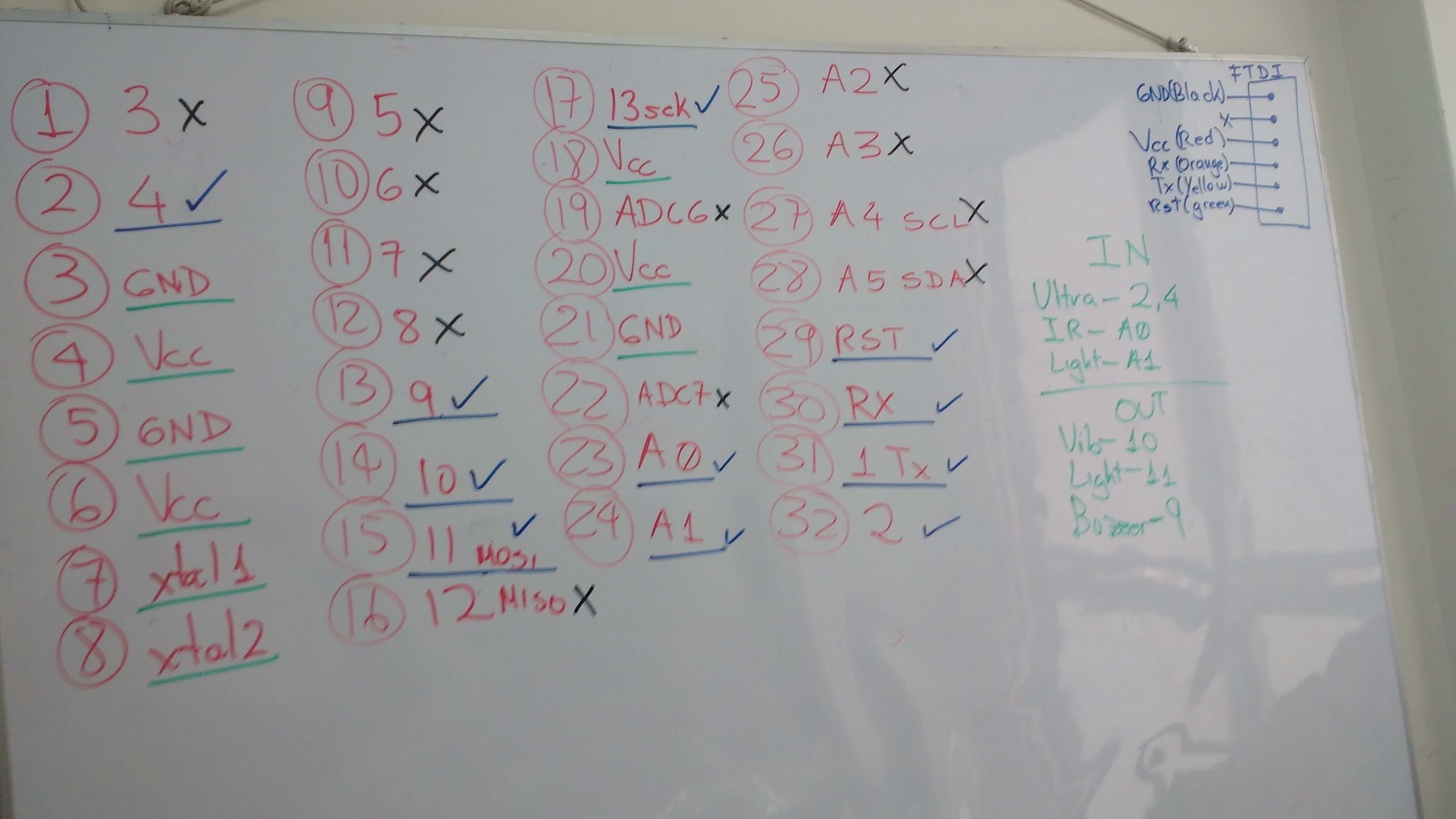
Here is the list of the pins and a correspondency between a satshakit, based on a 328p board and an arduino uno. In the picture the pins signed with an x means that this will not be availiable in the final design.
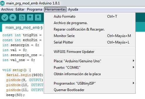
The configuration of the arduino IDE is that shown in the picture below.
And here is the video showing the software and hardware integration and funtion. This try is using an arduino uno with an atmel 328p, the ssame processor for my final project.
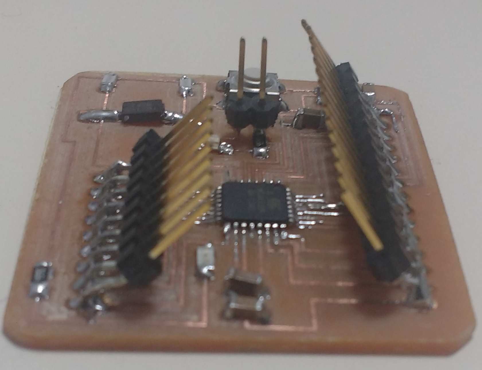
And for the final board design, such is in design phase the final physical view is something like this.
I try with other program languages, like python. So to probe the board with an Atmel ATMega328p doing something with a different environment i found ig GitHub a project called Python Arduino Prototyping API v2. (https://github.com/vascop/Python-Arduino-Proto-API-v2)
Here some basics commands to operate an 328P. From read and write:
#This is a little sample to read a value.
from arduino import Arduino
import time
b = Arduino('/dev/ttyUSB0')
pin = 3
b.output([])
while (True):
val = b.analogRead(pin)
print val
time.sleep(2)
#This is a little sample to write a value.
from arduino import Arduino
import time
b = Arduino('/dev/ttyUSB0')
pin = 13
#declare output pins as a list/tuple
b.output([pin])
brightness = 0
fadeAmount = 2
b.output([pin])
while (True):
b.analogWrite(pin, brightness)
time.sleep(0.1)
print b.analogRead(pin)
brightness = brightness + fadeAmount
if (brightness == 0 or brightness == 255):
fadeAmount = -fadeAmount
#This is a little sample to blink a led in to a pin 8
from arduino import Arduino
import time
b = Arduino('/dev/ttyUSB0')
pin = 8
#declare output pins as a list/tuple
b.output([pin])
for xrange(10):
b.setHigh(pin)
time.sleep(1)
print b.getState(pin)
b.setLow(pin)
print b.getState(pin)
time.sleep(1)
b.close()
from arduino import Arduino
import time
b = Arduino('/dev/ttyUSB0')
pin = 8
#declare output pins as a list/tuple
b.output([pin])
for xrange(10):
b.setHigh(pin)
time.sleep(1)
print b.getState(pin)
b.setLow(pin)
print b.getState(pin)
time.sleep(1)
b.close()
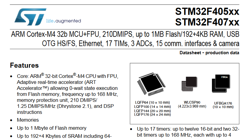
Additionally i try another microprocessor architecture called the STM32F405RG family, based on the high-performance ARM®Cortex®-M4 32-bit RISC core operating at a frequency of up to 168 MHz. The Cortex-M4 core features a Floating point unit (FPU) single precision which supports all ARM single-precision data-processing instructions and data types. It also implements a full set of DSP instructions and a memory protection unit (MPU) which enhances application security.
There is a online demo application to program it, and its available here: http://micropython.org/
The datasheet is availiable here.
There is a online demo application to program it, and its available here: http://micropython.org/
The datasheet is availiable here.
#This is a little sample to blink a led in the virtual board and move a servo motor using USR push button and to exit pushing RST button
from pyb import Servo
import time
import pyb
s1 = Servo(1) # servo on position 1 (X1, VIN, GND)
#turns servo to 0º
s1.angle(0) # move to 45 degrees
while True:
if pyb.Switch().value():
pyb.LED(3).on()
pyb.LED(4).off()
s1.angle(-85, 1500) # move to -85 degrees in 1500ms
time.sleep_ms(1000)
else:
pyb.LED(4).on()
pyb.LED(3).off()
s1.angle(45) # move to 45 degrees
time.sleep_ms(1000)
So, a little video with the program running is here:
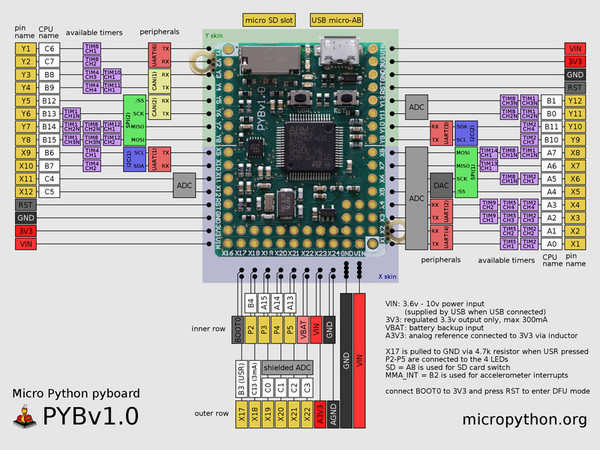
Here is the pinout explanaition about the board:
Here a link for the final NemoDuino finished.