


week 19
Assignment: complete your final project, tracking your progress:
what tasks have been completed, and what tasks remain?
what has worked? what hasn't?
what questions need to be resolved?
what will happen when?
what have you learned?
documentation during development
demand- vs supply-side time management
spiral development
system integration
finish
what tasks have been completed, and what tasks remain?
what has worked? what hasn't?
what questions need to be resolved?
what will happen when?
what have you learned?
documentation during development
demand- vs supply-side time management
spiral development
system integration
finish
Project Development.
Guillermo Jaramillo :: Fab Academy 2017
Fab Academy 2017

Robo blind stick General Plannig and Tasks
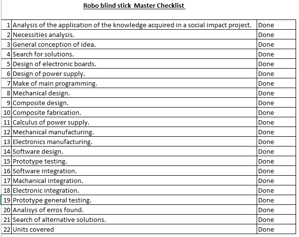
The steps or tasks in which the planning of this project has been applied are:
- Analysis of the application of the knowledge acquired in a social impact project.
The knowledge acquired through the Fab Academy, allows the student of the program, to propose highly technological solutions approaching the digital manufacture to the final user to literally leave the user level of consumption. This accumulation of knowledge should then facilitate the approach to technological products to people who in one way or another have limitations to be able to improve their quality and experience of life.
- Necessities analysis.
According to research in Peru (https://www.inei.gob.pe/media/MenuRecursivo/indices_tematicos/orden1_25.xlsx) the number of people with disabilities is 5.2 percent (about 170 thusands) and there are no low cost commercial solutions for Help people in this range especially if they are blind. This factor determined that the solution to be sought would be in this range.
- General conception of the idea.
Blind people may have difficulty interacting with their environment. Because it can be difficult to perceive where one is and moves from one place to another, the movement may become restricted, leading to little contact with the surrounding world. While other senses can be improved, this can be offset by a tendency to over-protection.
- Search for solutions.
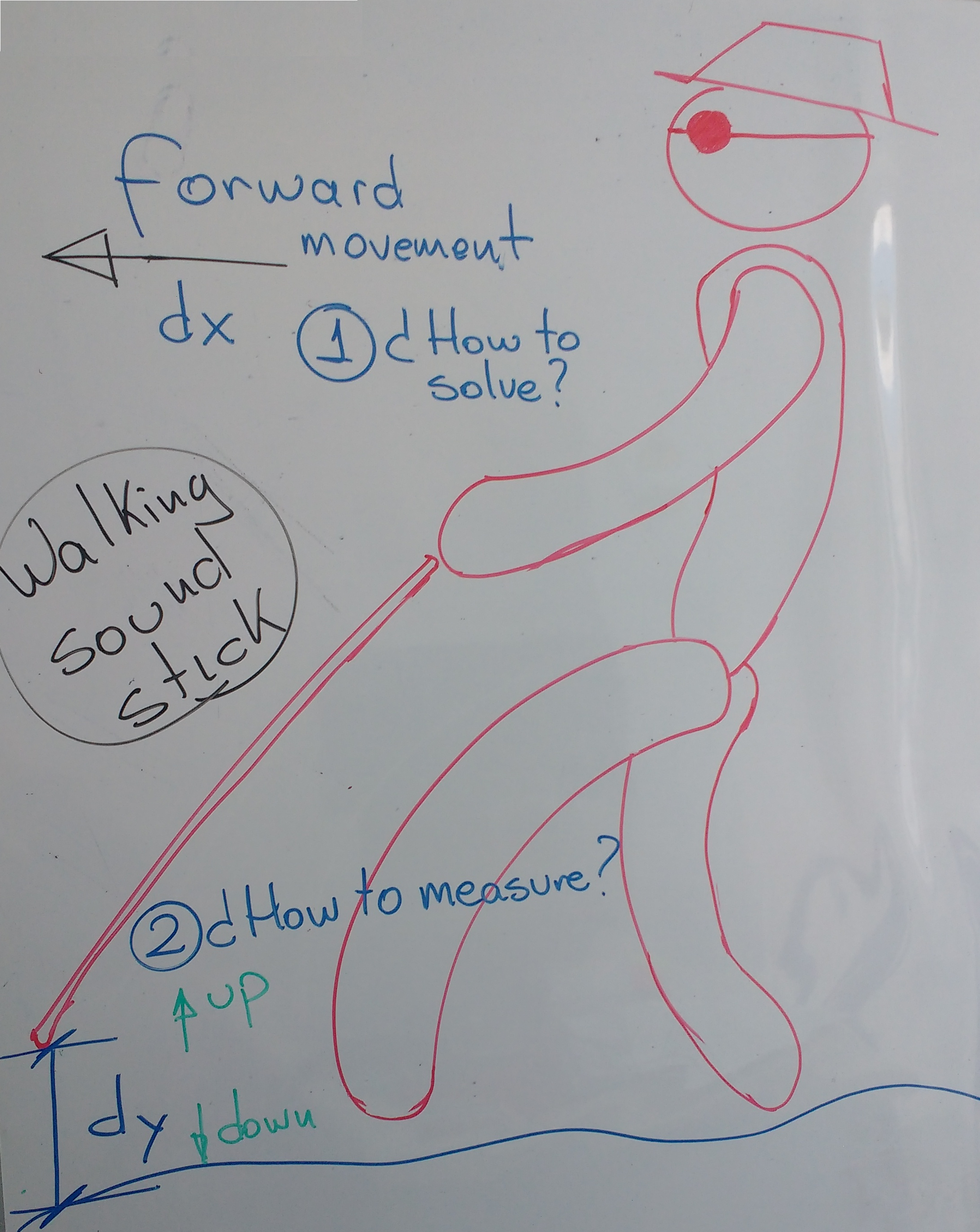
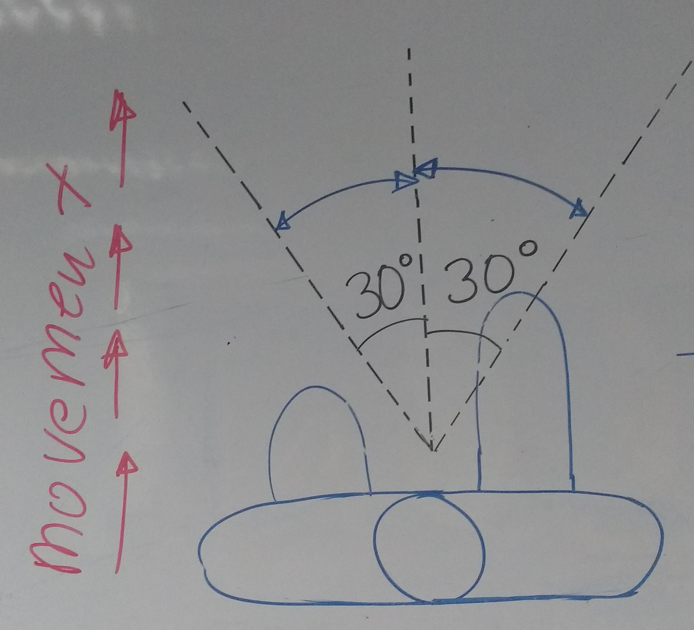
There were two main problems to solve:
1. The blind people make a sweep over the floor seeking an ob- stable or any object. This movement is represented by an angle moving the stick or cane about 30 degrees in both directions. This sweep is on a plane that I call XY plane. To solve this problem I will use an ultrasonic sensor. This sensor I can manufacture but not build because integrated circuits are not available in my country. For the output I will use a buzzer sensor, which I will not manufacture as it is very simple to make and can be obtained in the market for very low cost.
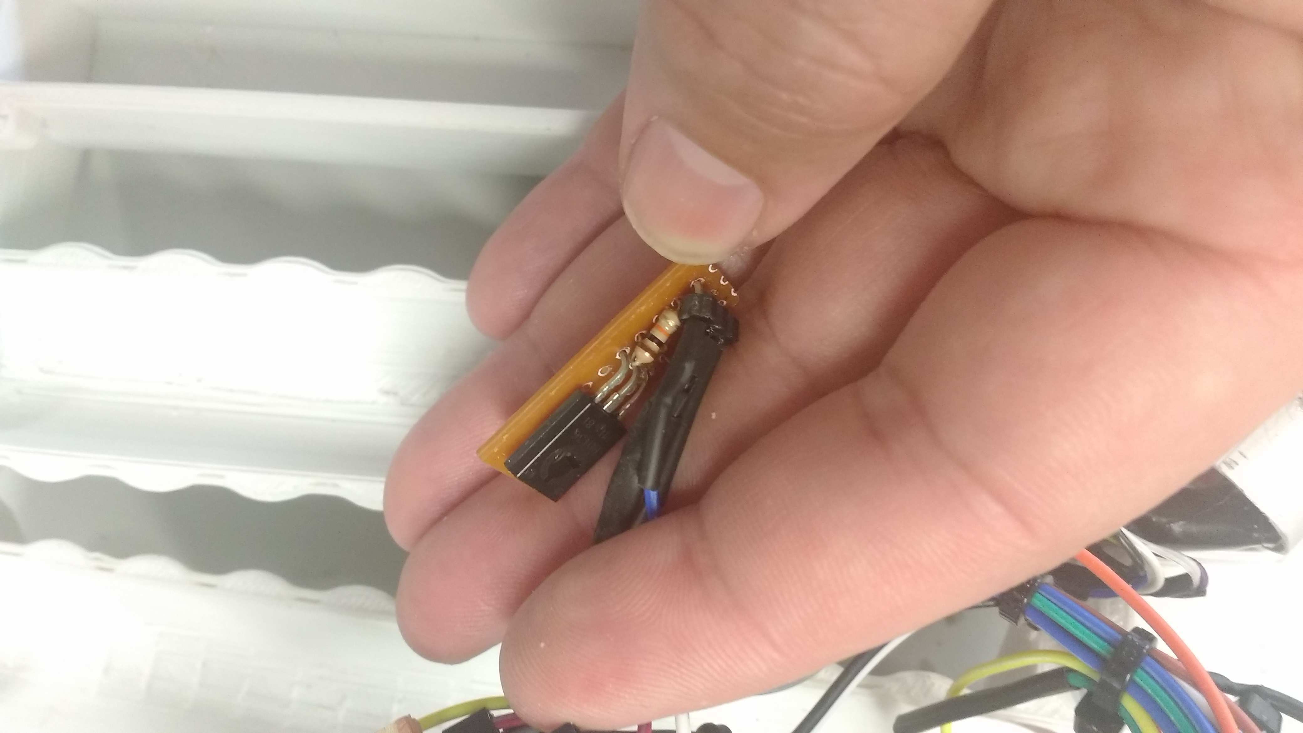
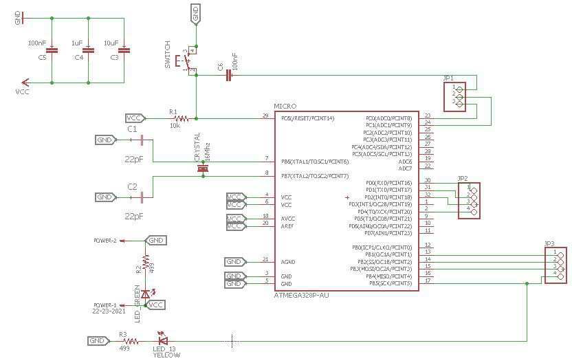
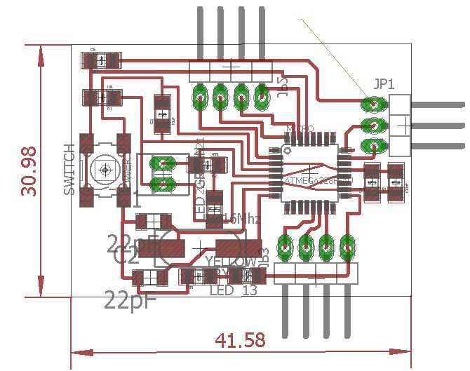
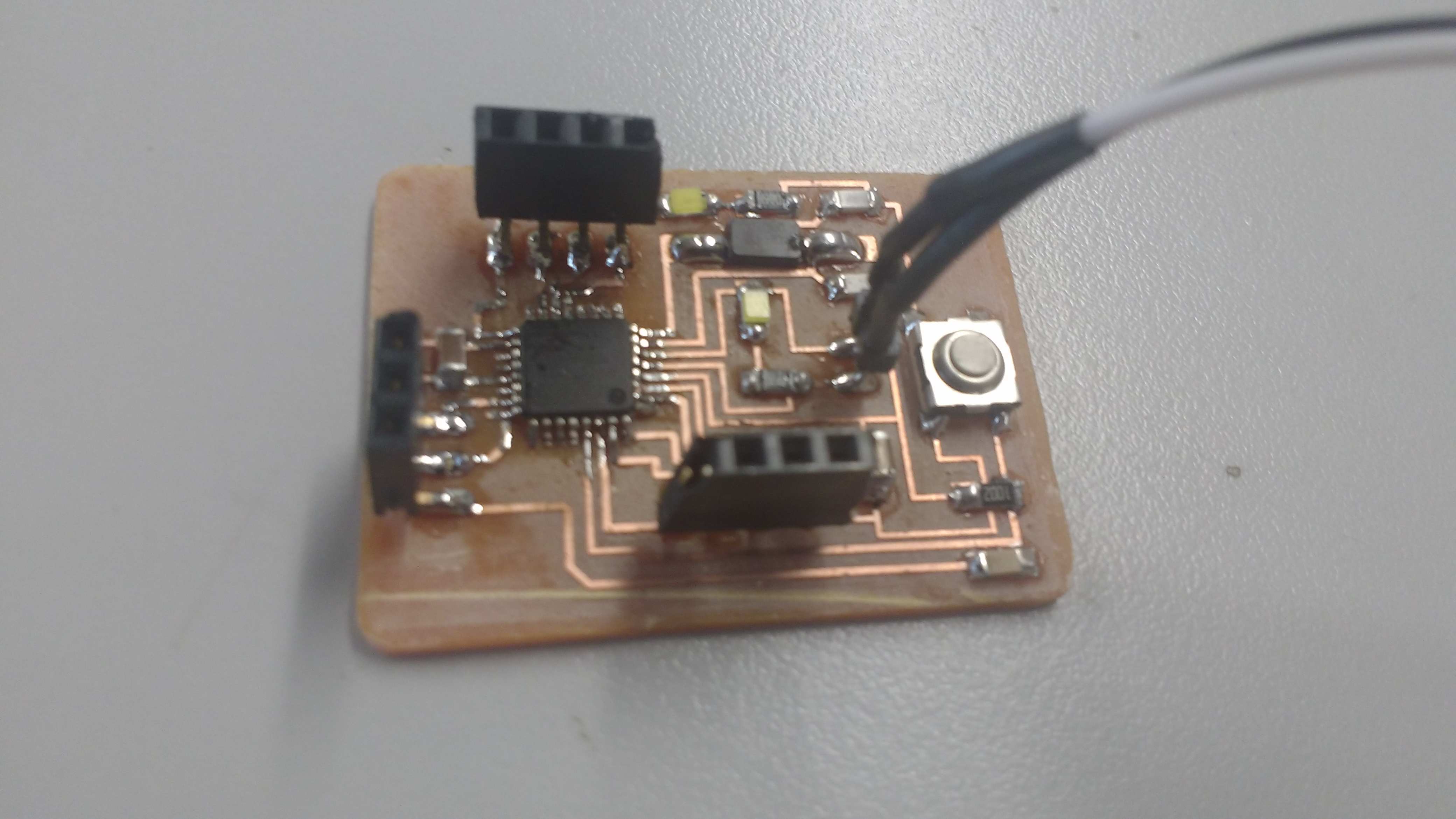
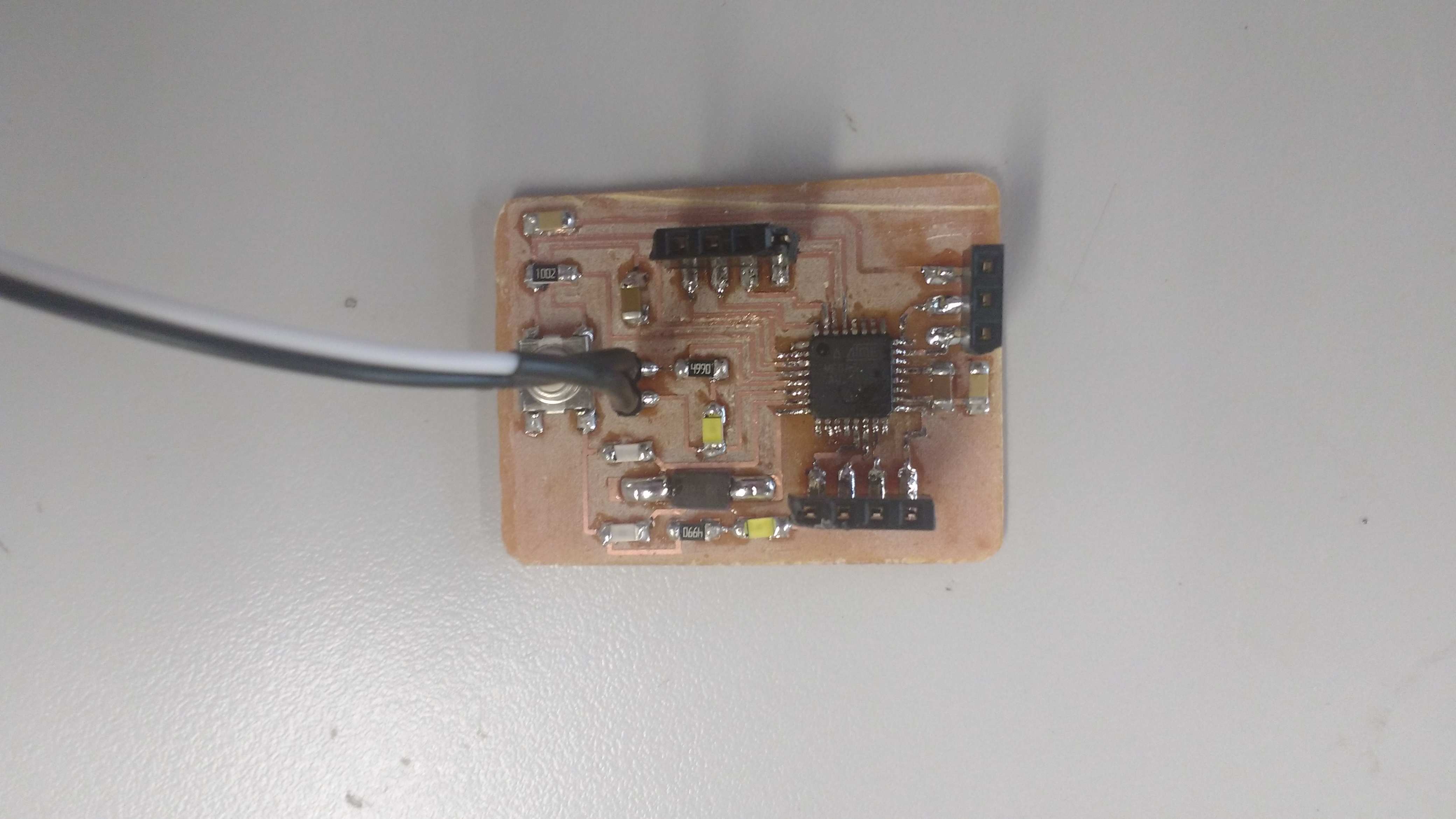
4. As a processor card I will use a customization of an Atmel 328P, modified as an equivalent of an arduino one, which I will use to perform the integration tests. The name of this version is Nemoduino 1.0 . I added female conectors to make more easy the electronic integration. More details of design here.
3. Another problem found is that blind people are not seen by other passers-by in the dark, for this I plan to put light on the body of the staff. For this I will use a light sensor which I will manufacture myself. As an output I will use a power driver to handle the ignition of a strip of LEDs.
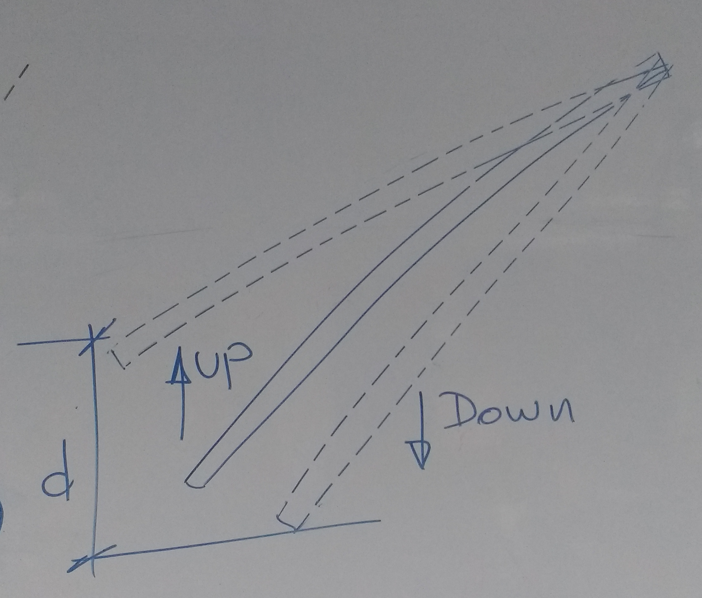
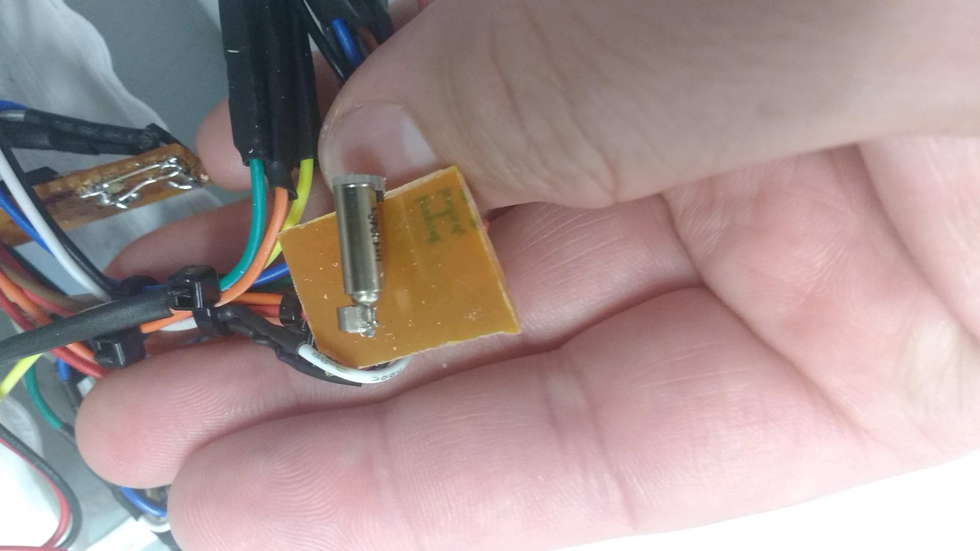
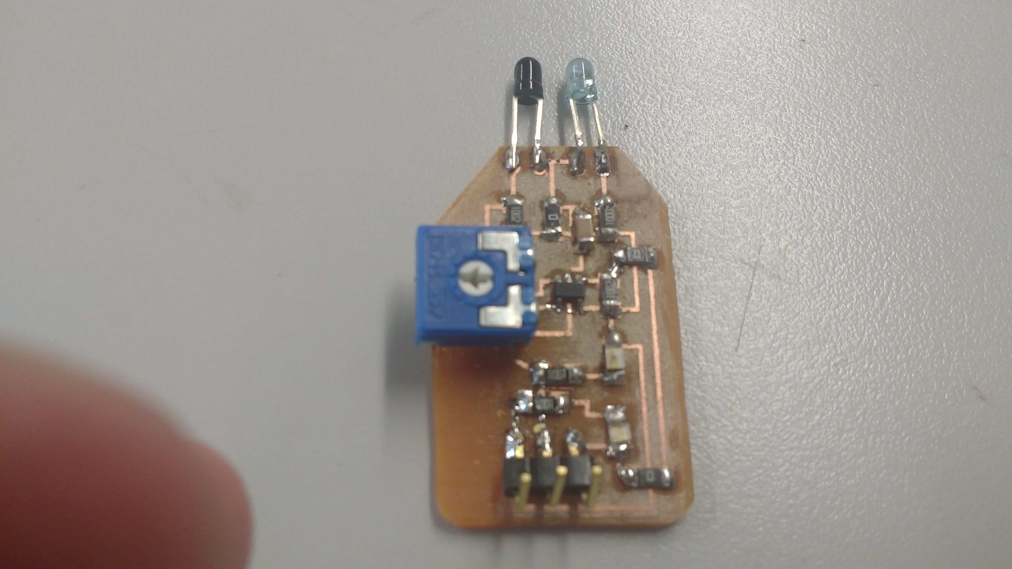
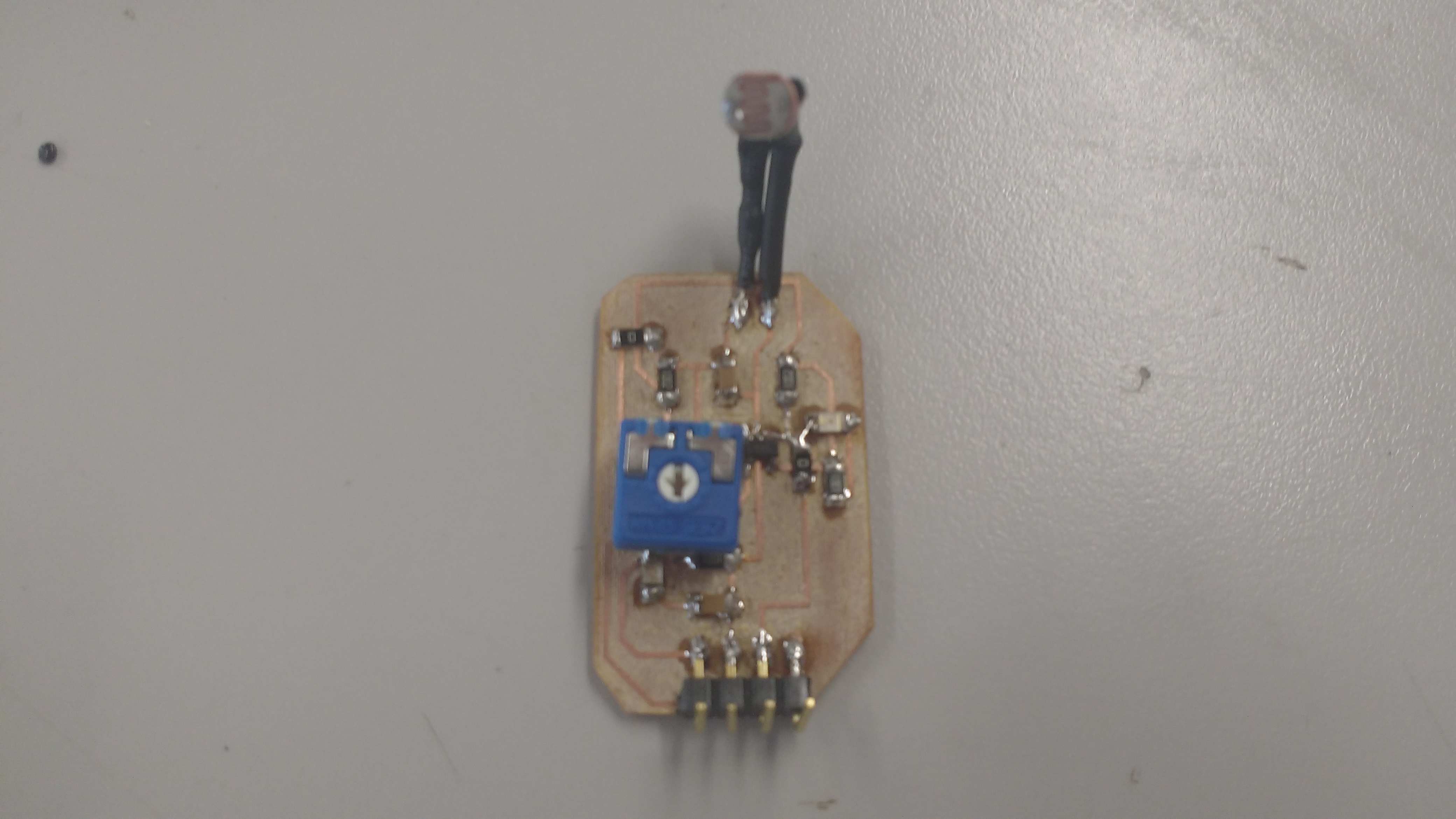
2. Other action makes by the blind people is in Z plane and consists to move up and down the cane to solve if there is a depression or a hole in the floor or something like a stair step. For this case I will use an IR input sensor, which I will manufacture as the electronics are available in Peru. As an output I will use an output sensor made up of a mobile vibrator motor driver.
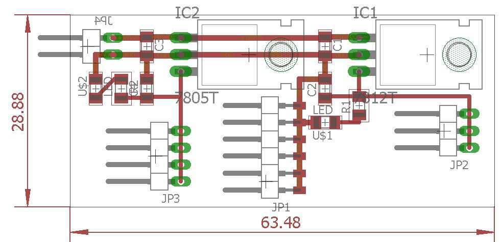
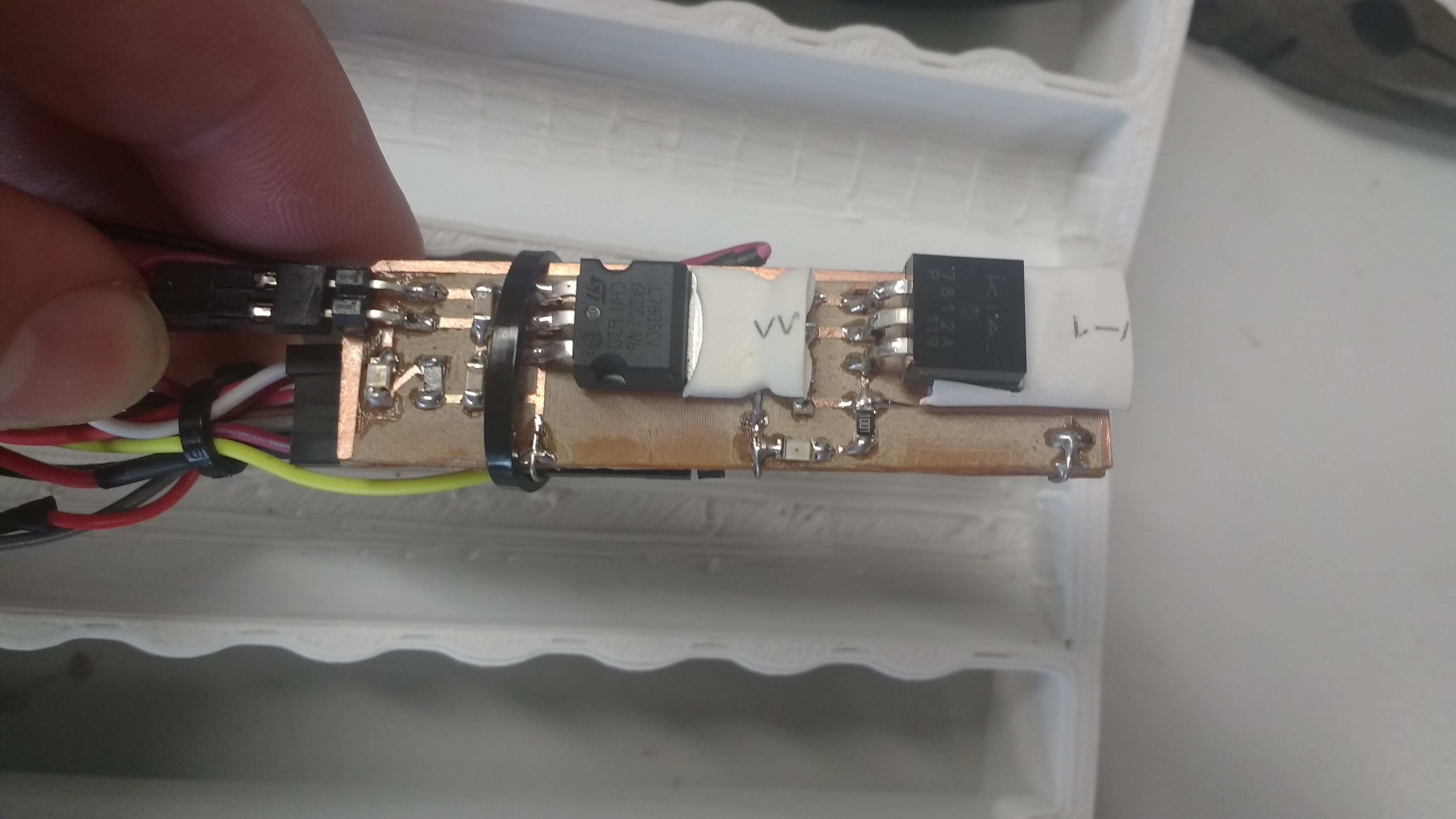
5. The power supply for the circuitry will be designed with an input voltage of up to 25 Vdc and two output voltages 12 Vdc and 5 Vdc.

I made a personal board for output device and drive 66 leds strip using an NPN transistor and a 10k Ohm to polarize the base of the device.
6. Programming I will do it in the arduino IDE, because it is very simple to operate and the degree of complexity of the project in terms of software is not very critical.
/* * VCC connection of the sensor attached to +5V
* GND connection of the sensor attached to ground
* TRIG connection of the sensor attached to digital pin 2
* ECHO connection of the sensor attached to digital pin 4
*/
const int trigPin = 2;
const int echoPin = 4;
int sensorpin = 0; // analog pin used to connect the sharp sensor
int val = 0; // variable to store the values from sensor(initially zero)
int sensorpin_one = A1; // analog pin used to connect the sharp sensor
int val_one = 0; // variable to store the values from sensor(initially zero)
/*int IRpin = A0; // IR photodiode on analog pin A0
//int IRemitter = 3; // IR emitter LED on digital pin 3
int ambientIR; // variable to store the IR coming from the ambient
int obstacleIR; // variable to store the IR coming from the object
int value[10]; // variable to store the IR values
int distance; // variable that will tell if there is an obstacle or not*/
void setup() {
// initialize serial communication:
Serial.begin(9600);
pinMode(9, OUTPUT);
pinMode(10,OUTPUT);
pinMode(11,OUTPUT);
beep(50);
beep(50);
beep(50);
delay(1000);
/* pinMode(IRemitter,OUTPUT); // IR emitter LED on digital pin 3
digitalWrite(IRemitter,LOW);// setup IR LED as off
pinMode(11,OUTPUT); // buzzer in digital pin 11*/
}
void loop()
{
val = analogRead(sensorpin); // reads the value of the sharp sensor
Serial.println(val); // prints the value of the sensor to the serial monitor
if (val<100)
{
digitalWrite(11,HIGH);
delay(55);
digitalWrite(11,LOW);
}
delay(400); // wait for this much time before printing next value
val_one = analogRead(sensorpin_one); // reads the value of the sharp sensor
Serial.println(val_one); // prints the value of the sensor to the serial monitor
if (val_one>700)
{
digitalWrite(10,HIGH);
}
else
{
digitalWrite(10,LOW);
}
/* distance = readIR(5); // calling the function that will read the distance and passing the "accuracy" to it
Serial.println(distance); // writing the read value on Serial monitor
buzzer(); // uncomment to activate the buzzer function*/
// establish variables for duration of the ping,
// and the distance result in inches and centimeters:
long duration, cm;
// The sensor is triggered by a HIGH pulse of 10 or more microseconds.
// Give a short LOW pulse beforehand to ensure a clean HIGH pulse:
pinMode(trigPin, OUTPUT);
digitalWrite(trigPin, LOW);
delayMicroseconds(2);
digitalWrite(trigPin, HIGH);
delayMicroseconds(10);
digitalWrite(trigPin, LOW);
// Read the signal from the sensor: a HIGH pulse whose
// duration is the time (in microseconds) from the sending
// of the ping to the reception of its echo off of an object.
pinMode(echoPin, INPUT);
duration = pulseIn(echoPin, HIGH);
// convert the time into a distance
cm = microsecondsToCentimeters(duration);
if (cm<200)
{
beep(500);
beep(500);
beep(500);
}
// Serial.print(cm);
// Serial.print("cm");
// Serial.println();
delay(100);
}
long microsecondsToCentimeters(long microseconds)
{
return microseconds / 29 / 2;
}
void beep(unsigned char pausa)
{
analogWrite(9, 20);
delay(pausa); // Espera
analogWrite(9, 0); // Apaga
delay(pausa); // Espera
}
/*int readIR(int times){
for(int x=0;x<times;x++){
digitalWrite(IRemitter,LOW); // turning the IR LEDs off to read the IR coming from the ambient
delay(1); // minimum delay necessary to read values
ambientIR = analogRead(IRpin); // storing IR coming from the ambient
digitalWrite(IRemitter,HIGH); // turning the IR LEDs on to read the IR coming from the obstacle
delay(1); // minimum delay necessary to read values
obstacleIR = analogRead(IRpin); // storing IR coming from the obstacle
value[x] = ambientIR-obstacleIR; // calculating changes in IR values and storing it for future average
}
for(int x=0;x<times;x++){ // calculating the average based on the "accuracy"
distance+=value[x];
}
return(distance/times); // return the final value
}
//-- Function to sound a buzzer for audible measurements --//
void buzzer(){
if (distance>1){
if(distance>100){ // continuous sound if the obstacle is too close
digitalWrite(11,HIGH);
}
else{ // beeps faster when an obstacle approaches
digitalWrite(11,HIGH);
delay(150-distance); // adjust this value for your convenience
digitalWrite(11,LOW);
delay(150-distance); // adjust this value for your convenience
}
}
else{ // off if there is no obstacle
digitalWrite(11,LOW);
}
}*/
- Design and creation of software.
For this the use of the arduino IDE has been made, with which due to the equivalence between the processors I have proceeded to use the instructions compatible with an Atmel 328P.
- Prototype testing.
The prototype test was done using an arduino one and commercial sensors compatible with arduino.
- Software integration.
Software integration consists of testing the acquisition codes of each sensor as input elements. Then integration is done with the output action. Finally the calibration of the sensor and the output actuator is done through a trigger. Click here to see the previous version of main program. Full version of software was showed lines up in the 6. section.
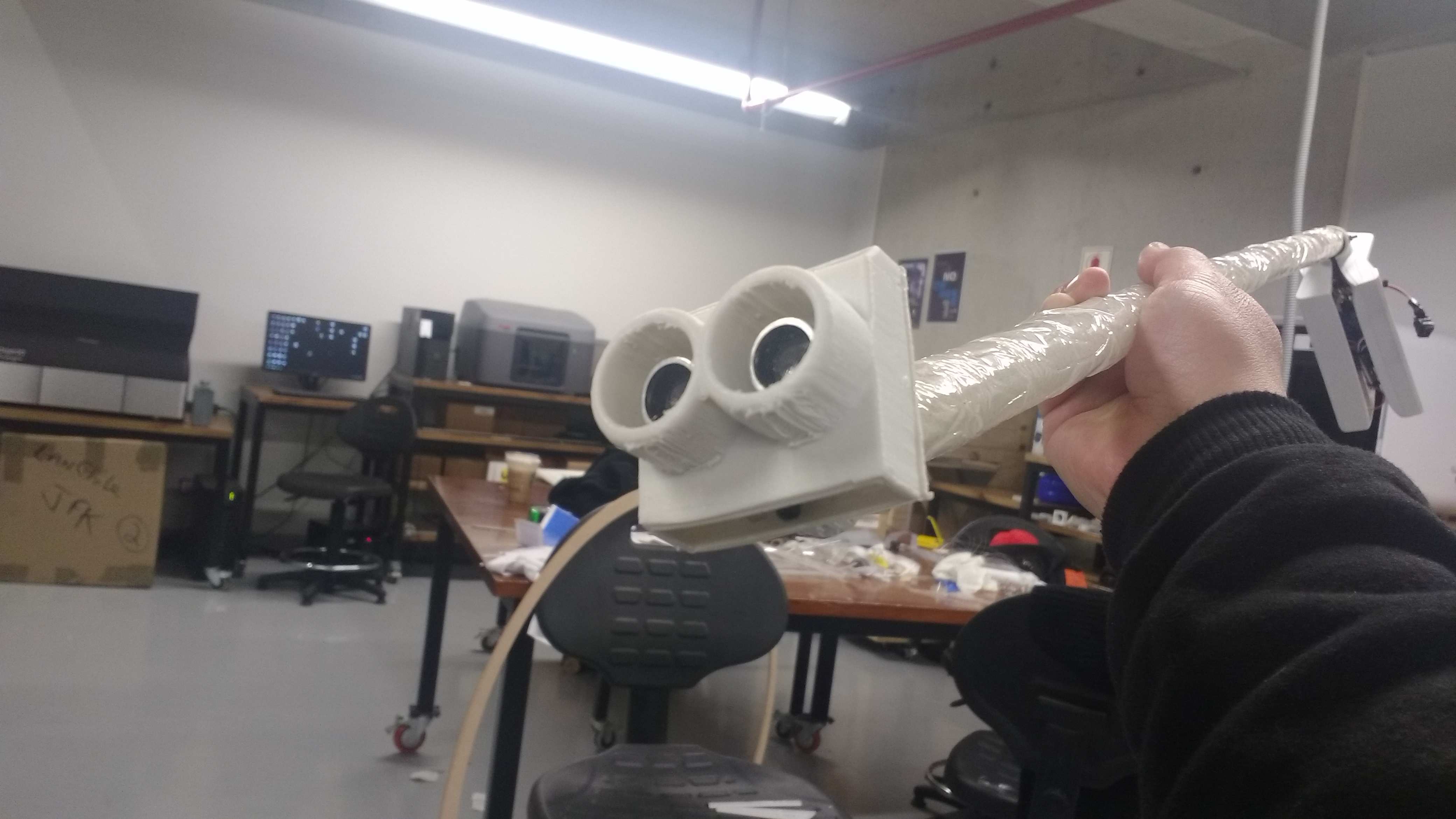
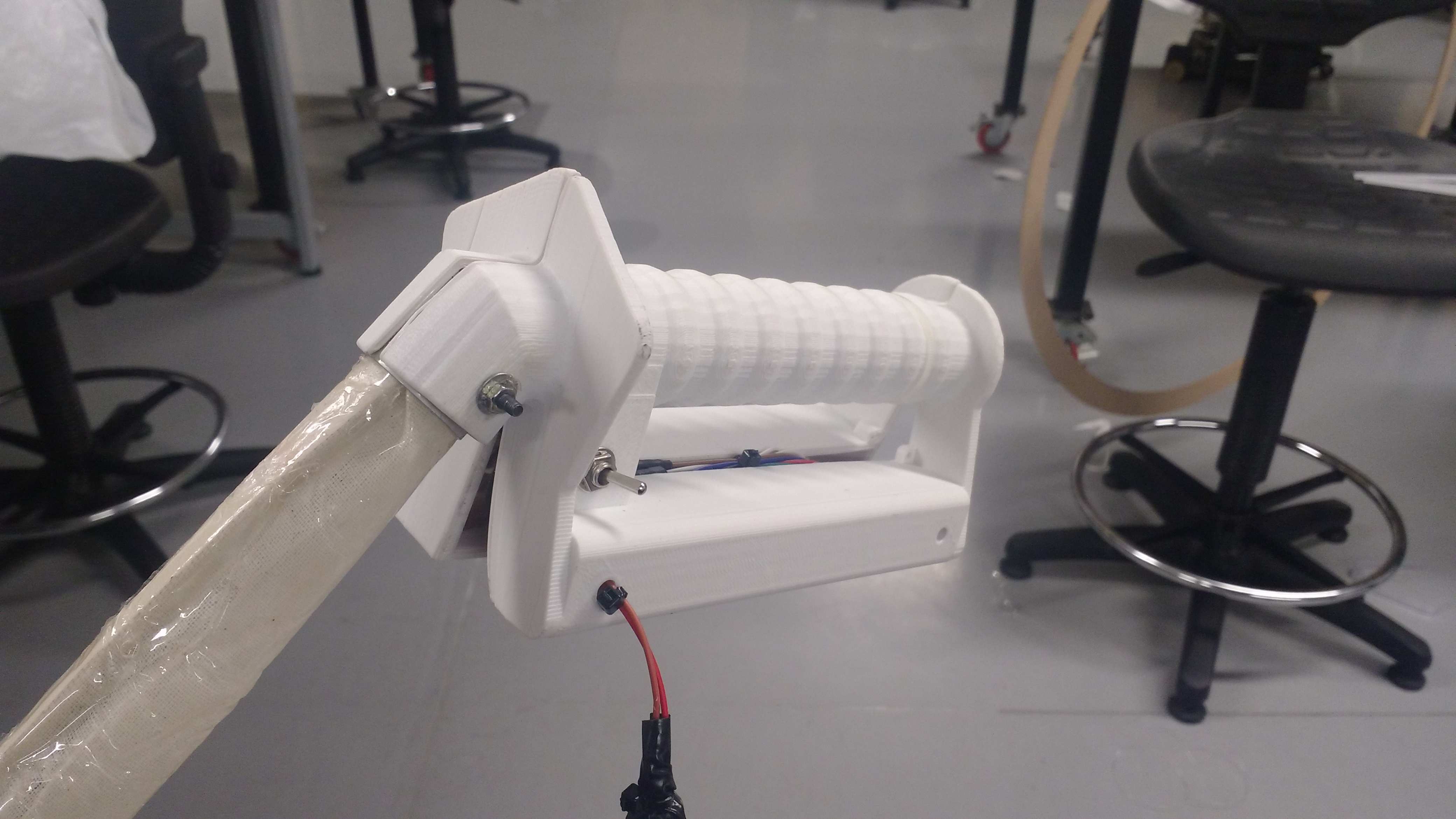
- Mechanical integration.
For mechanical integration it has been necessary to use certain elements such as aluminum washers and pressure washers to be able to fix the elements together. (Neb to body - body to handler)
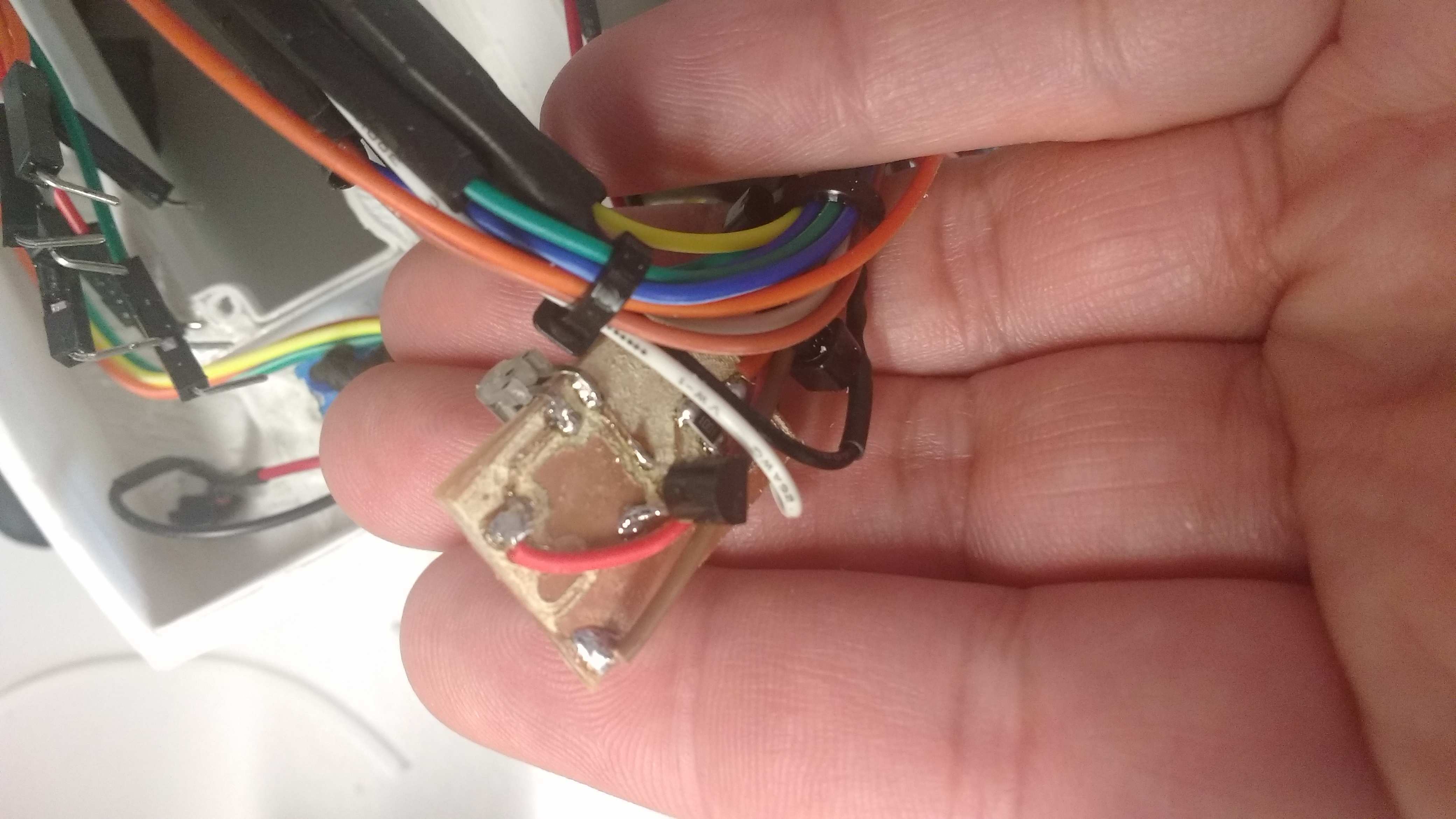
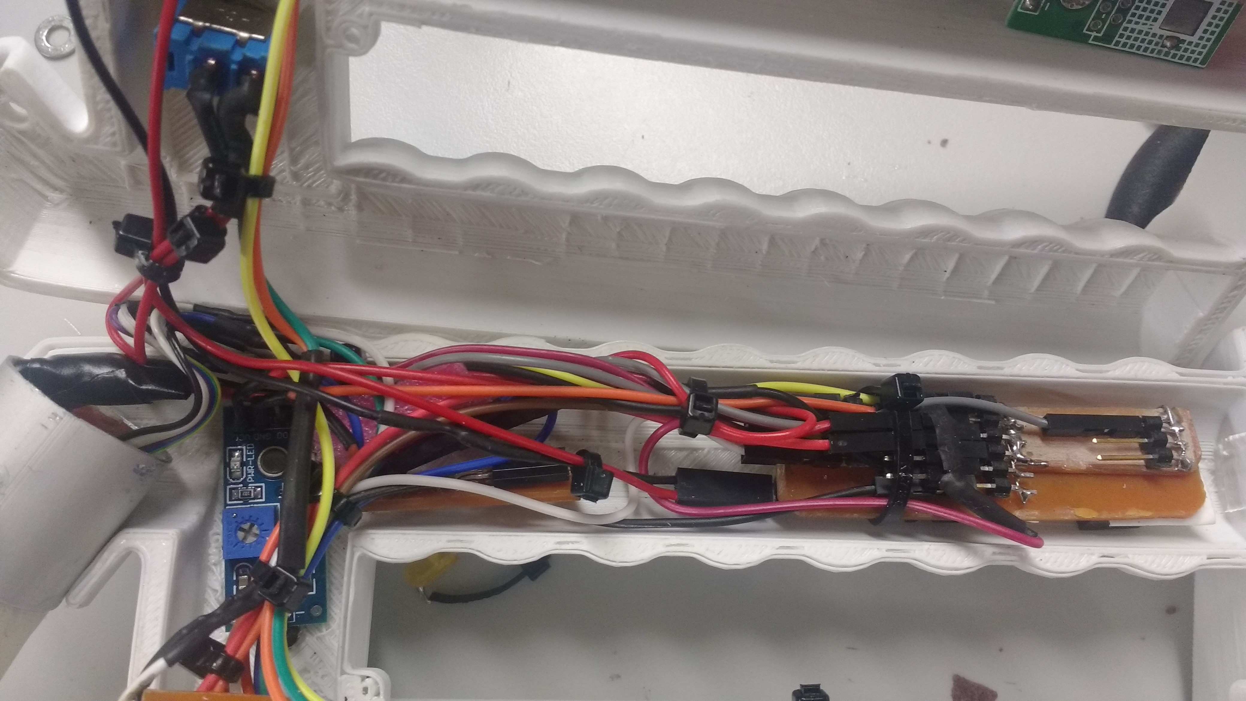
- Electronic integration.
In order to carry out the electronic integration, it was necessary to contemplate the use of connections with thermo-
shrinkable sheath, the use of flat cables to avoid the clutter of the wiring, and the cables to secure the cables in place. Another general test is the power supply to test its operation and correct operation when feeding the various circuits.
- Prototype general test.
The general prototype tests have been done in terms of mechanical and programming parts satisfactorily. As for the electronics I had problems to satisfy the current of consumption which is almost of an ampere.
- Analysis of errors found.
There are two errors in the total project development. One is the accelerometer sensor that was not possible integrate by sizes problems and current consumption errors and twice, the error of calculation of the current of consumption I proposed to change the power momentarily by an external source.
- Alternative solutions.
To solve the first problem is modify the size of handler to receive the accelerometer sensor and to fix the second problem I propose in future versions to use lithium polymer batteries of these characteristics:
Battery Lipo 3AH 18.5V 3000mAh 5S 20C
Characteristics:
Lithium Polymer Battery.
- Minimum Capacity: 3Ah
- Configuration: 3S1P / 18.5v / 3cells
- Download: 30C
- Discharge pressure (10sec): 40C
- Weight: 220 g
- Dimensions: 145 x 49 x 27 mm
- Plug of load: JST-XH
- Discharge plug: 5.5mm Bullet-connector.
- Evaluation of the project.
I believe that the aspects to be evaluated are relevance, inclusion and social impact, creativity, level of integration, aspects of STEM covered, the number of Fab Academy units covered in the project.
- Units covered.
The units covered in the project are:
* Principles and practices, project management
* Computer-aided design
* Computer-controlled cutting
* Electronics production
* 3D scanning and printing
* Electronics design
* Computer-controlled machining
* Embedded programming
* Output devices
* Machine design
* Input devices
* Composites.
- Presentation of the project.
See the final testing of project in this video.
For this the use of the arduino IDE has been made, with which due to the equivalence between the processors I have proceeded to use the instructions compatible with an Atmel 328P.
- Prototype testing.
The prototype test was done using an arduino one and commercial sensors compatible with arduino.
- Software integration.
Software integration consists of testing the acquisition codes of each sensor as input elements. Then integration is done with the output action. Finally the calibration of the sensor and the output actuator is done through a trigger. Click here to see the previous version of main program. Full version of software was showed lines up in the 6. section.
- Mechanical integration.
For mechanical integration it has been necessary to use certain elements such as aluminum washers and pressure washers to be able to fix the elements together. (Neb to body - body to handler)
- Electronic integration.
In order to carry out the electronic integration, it was necessary to contemplate the use of connections with thermo-
shrinkable sheath, the use of flat cables to avoid the clutter of the wiring, and the cables to secure the cables in place. Another general test is the power supply to test its operation and correct operation when feeding the various circuits.
- Prototype general test.
The general prototype tests have been done in terms of mechanical and programming parts satisfactorily. As for the electronics I had problems to satisfy the current of consumption which is almost of an ampere.
- Analysis of errors found.
There are two errors in the total project development. One is the accelerometer sensor that was not possible integrate by sizes problems and current consumption errors and twice, the error of calculation of the current of consumption I proposed to change the power momentarily by an external source.
- Alternative solutions.
To solve the first problem is modify the size of handler to receive the accelerometer sensor and to fix the second problem I propose in future versions to use lithium polymer batteries of these characteristics:
Battery Lipo 3AH 18.5V 3000mAh 5S 20C
Characteristics:
Lithium Polymer Battery.
- Minimum Capacity: 3Ah
- Configuration: 3S1P / 18.5v / 3cells
- Download: 30C
- Discharge pressure (10sec): 40C
- Weight: 220 g
- Dimensions: 145 x 49 x 27 mm
- Plug of load: JST-XH
- Discharge plug: 5.5mm Bullet-connector.
- Evaluation of the project.
I believe that the aspects to be evaluated are relevance, inclusion and social impact, creativity, level of integration, aspects of STEM covered, the number of Fab Academy units covered in the project.
- Units covered.
The units covered in the project are:
* Principles and practices, project management
* Computer-aided design
* Computer-controlled cutting
* Electronics production
* 3D scanning and printing
* Electronics design
* Computer-controlled machining
* Embedded programming
* Output devices
* Machine design
* Input devices
* Composites.
- Presentation of the project.
See the final testing of project in this video.
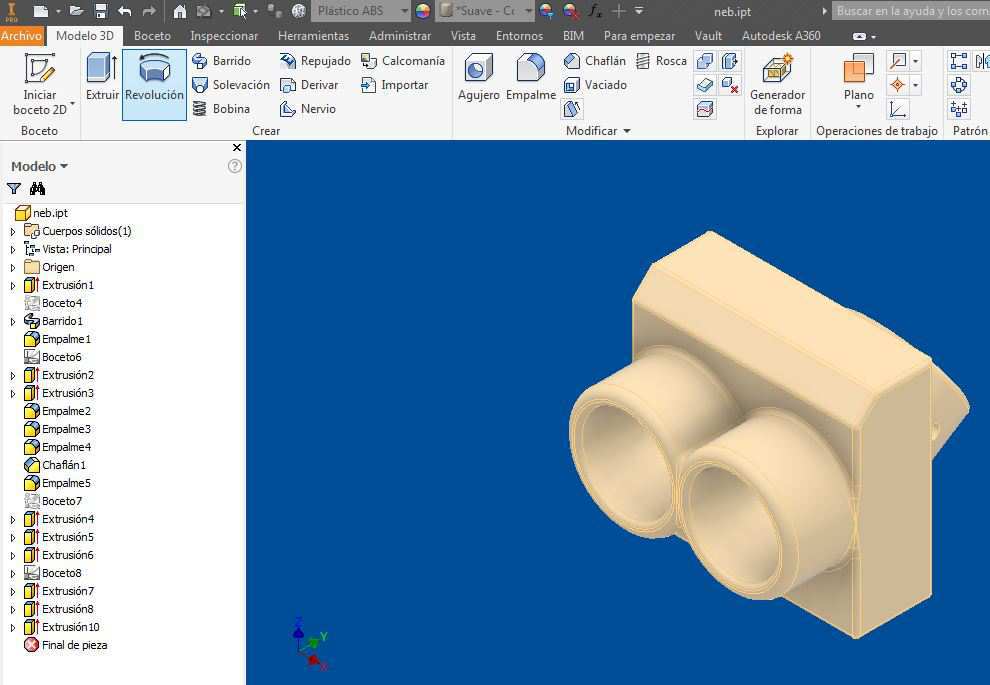
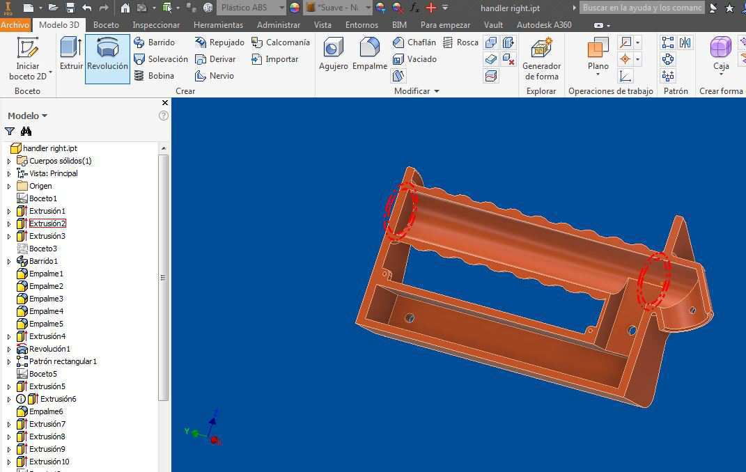
7. The designs of the mechanical parts will be done using Autodesk Inventor 2017 for both the neb and the handle.
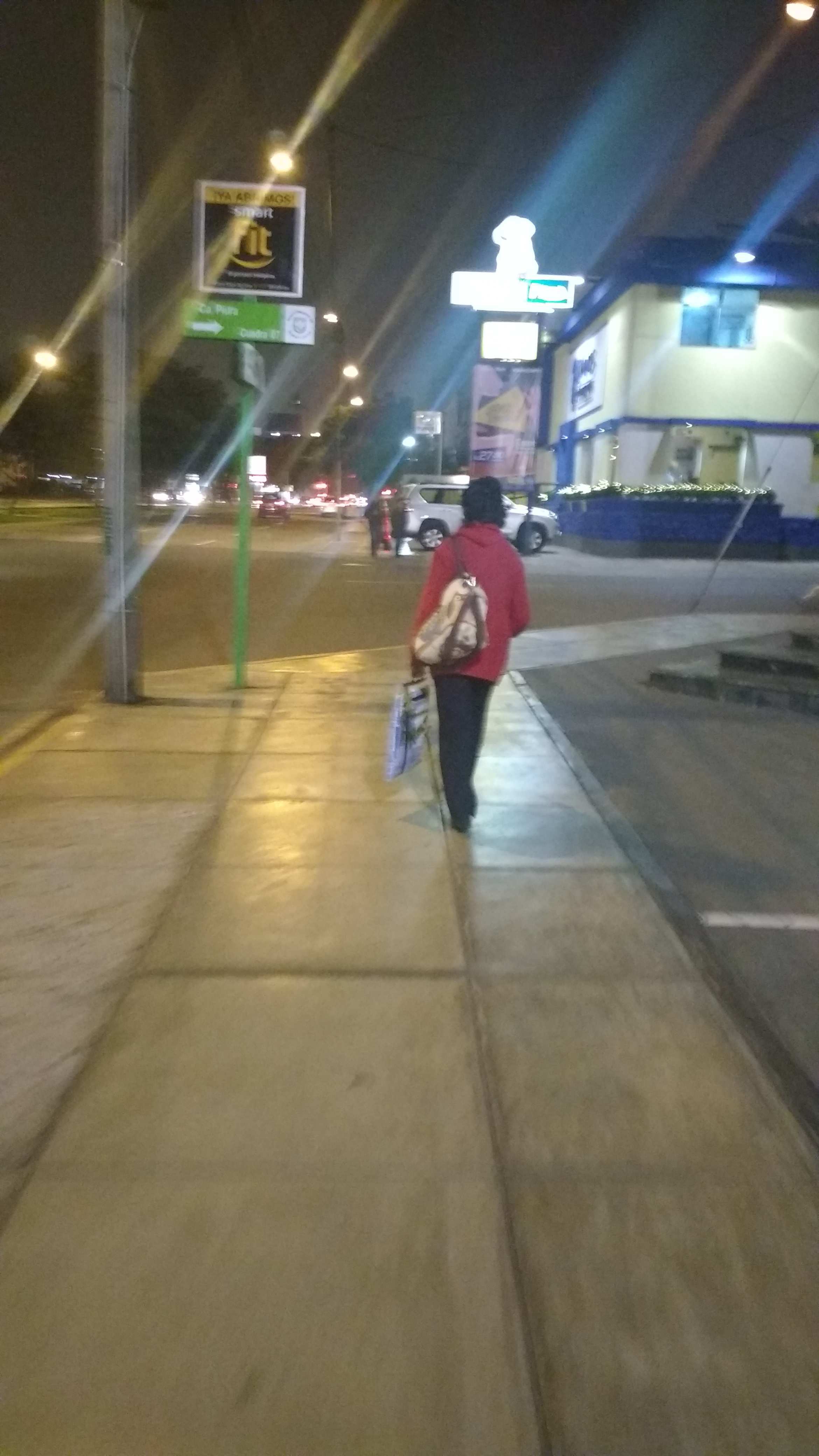
8. The body of the stick will be made using resin composed with tufted cloth. But the design concepts needs to define how too long must be or in engineering terms what is the relation between the human body and the height of the stick's body. To determine this i use a simple way to measure the right angles showed in this pictures.
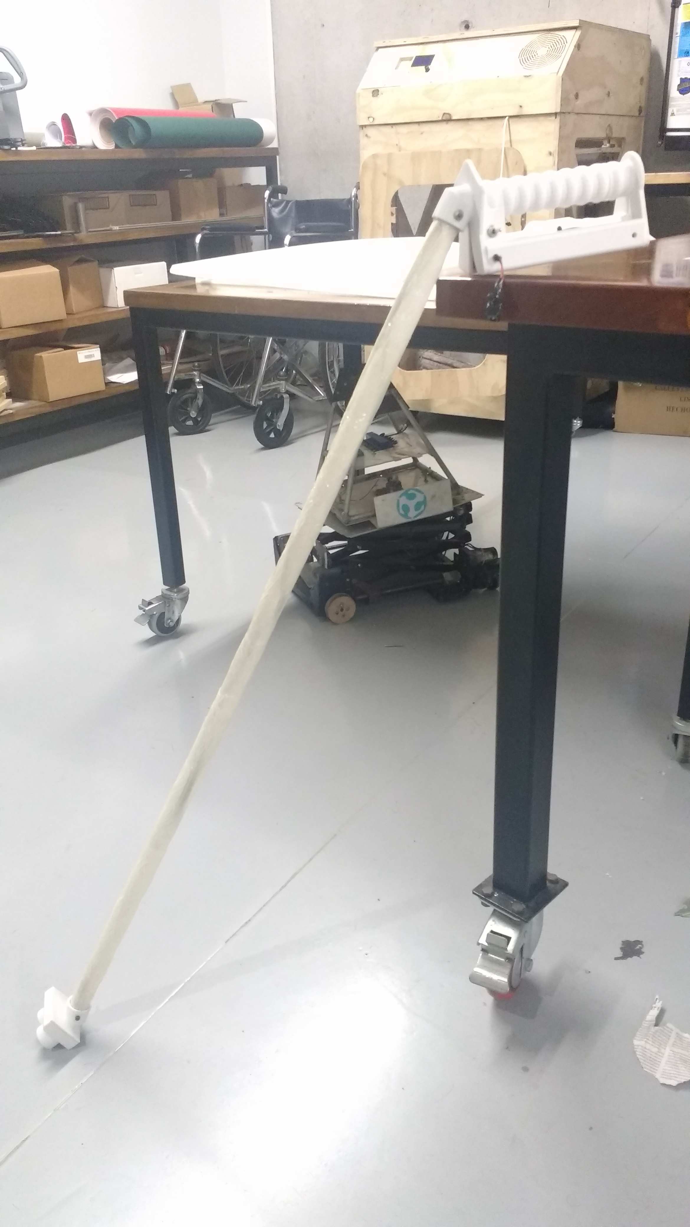
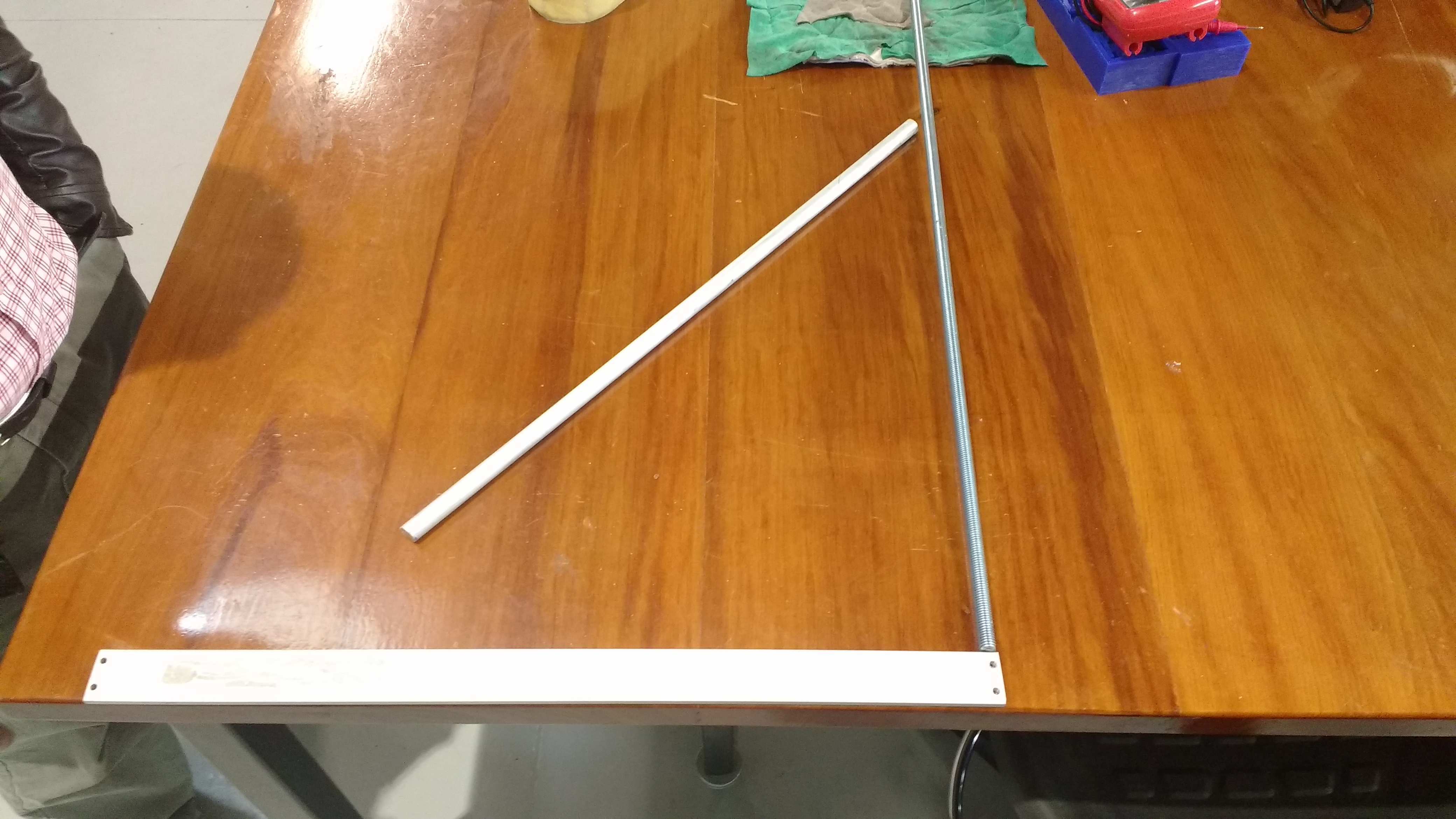
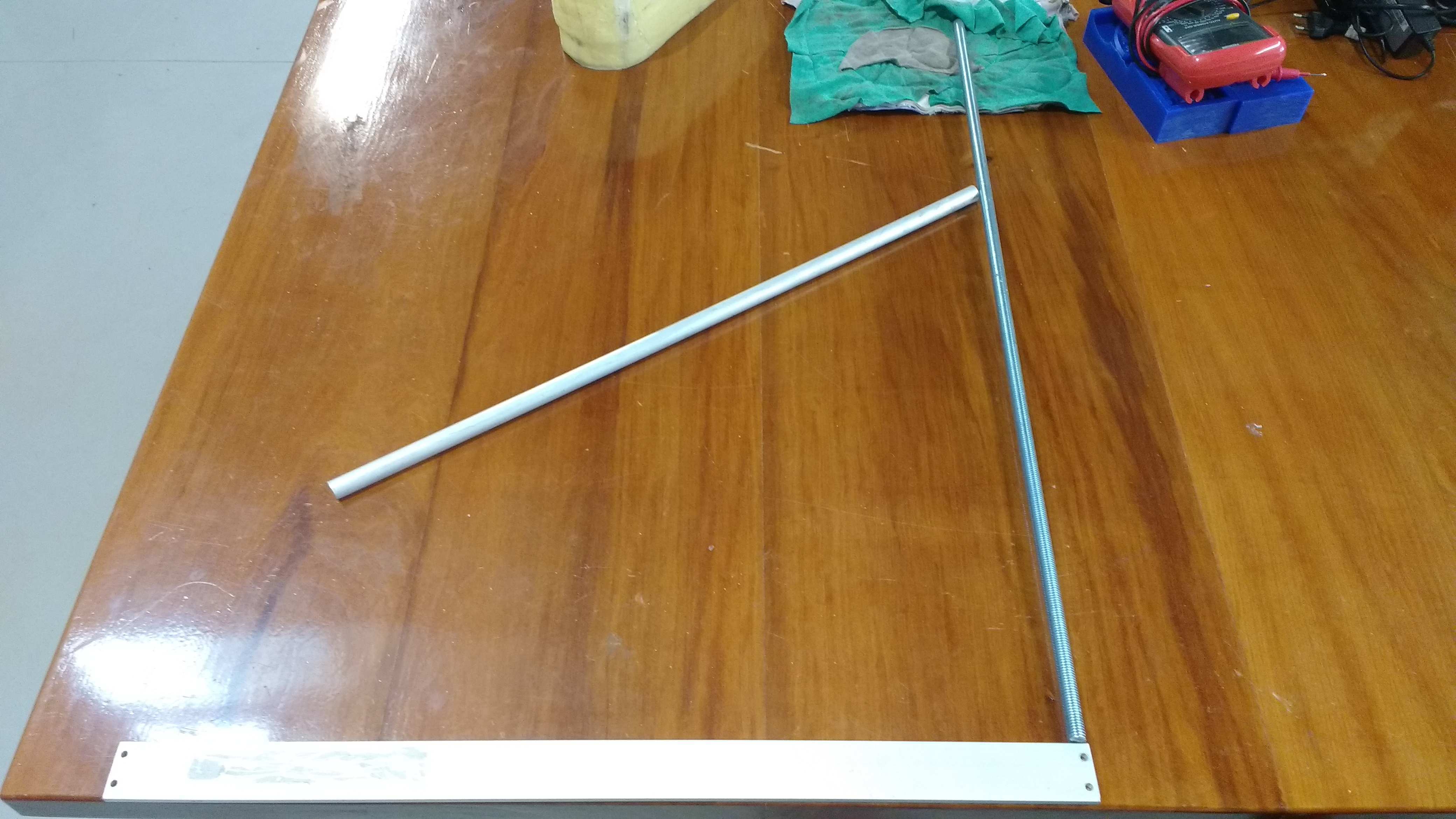
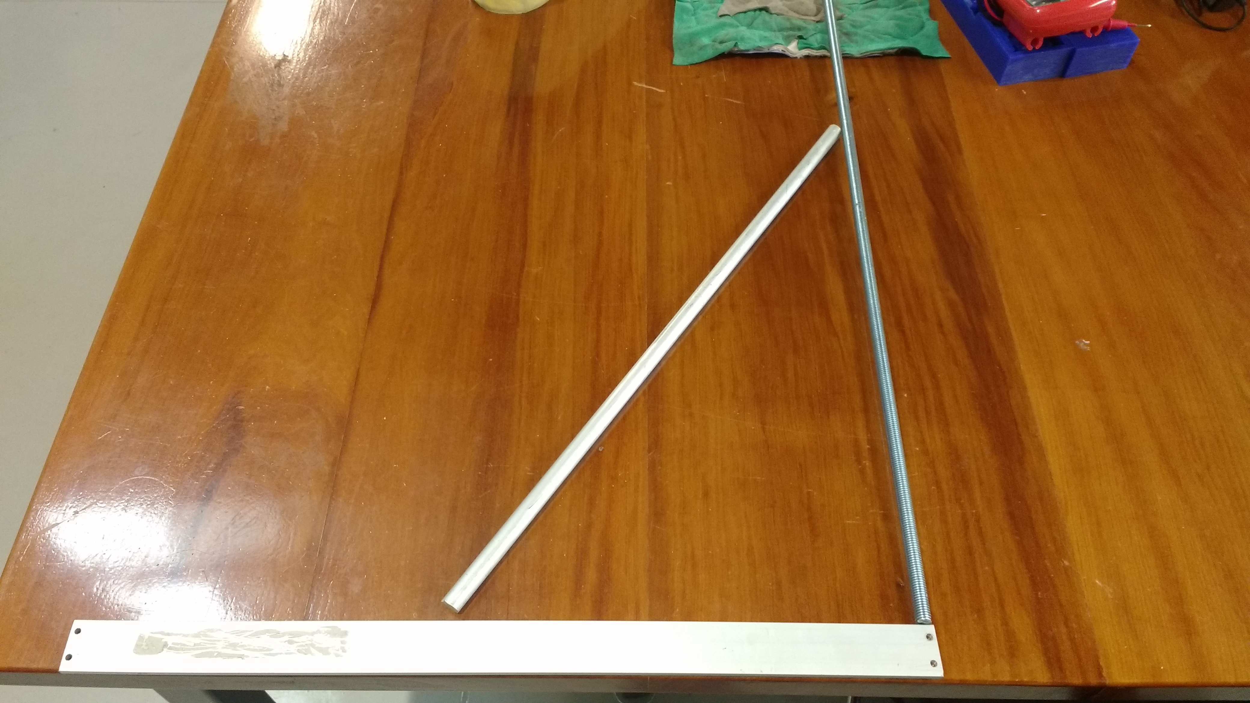
Normal operation Angles like 60º.
Highest operation Angles like 75º.
Lower operation Angles like 48º.
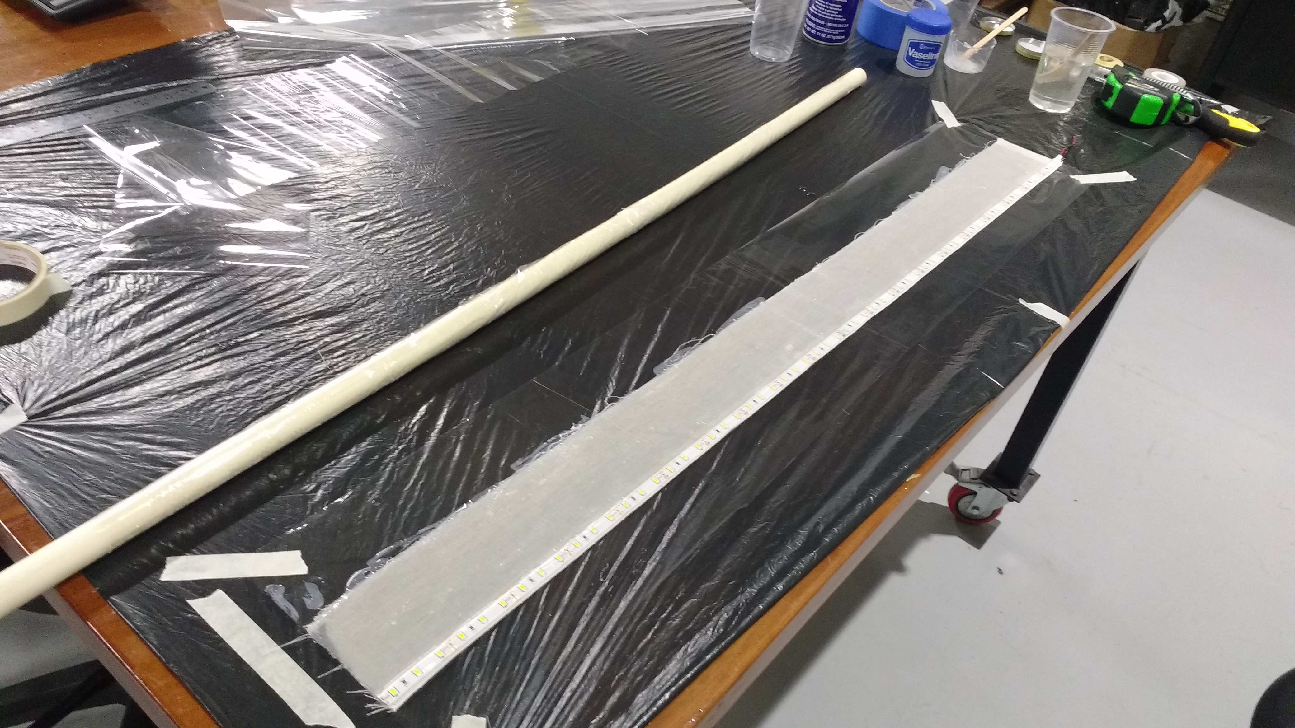
To make the compo body, i thought that is just only needed a PVC plastic pipe and a compo body of tocuyo and epoxic resin, vaseline, WD40 as demoldant, film plastic.
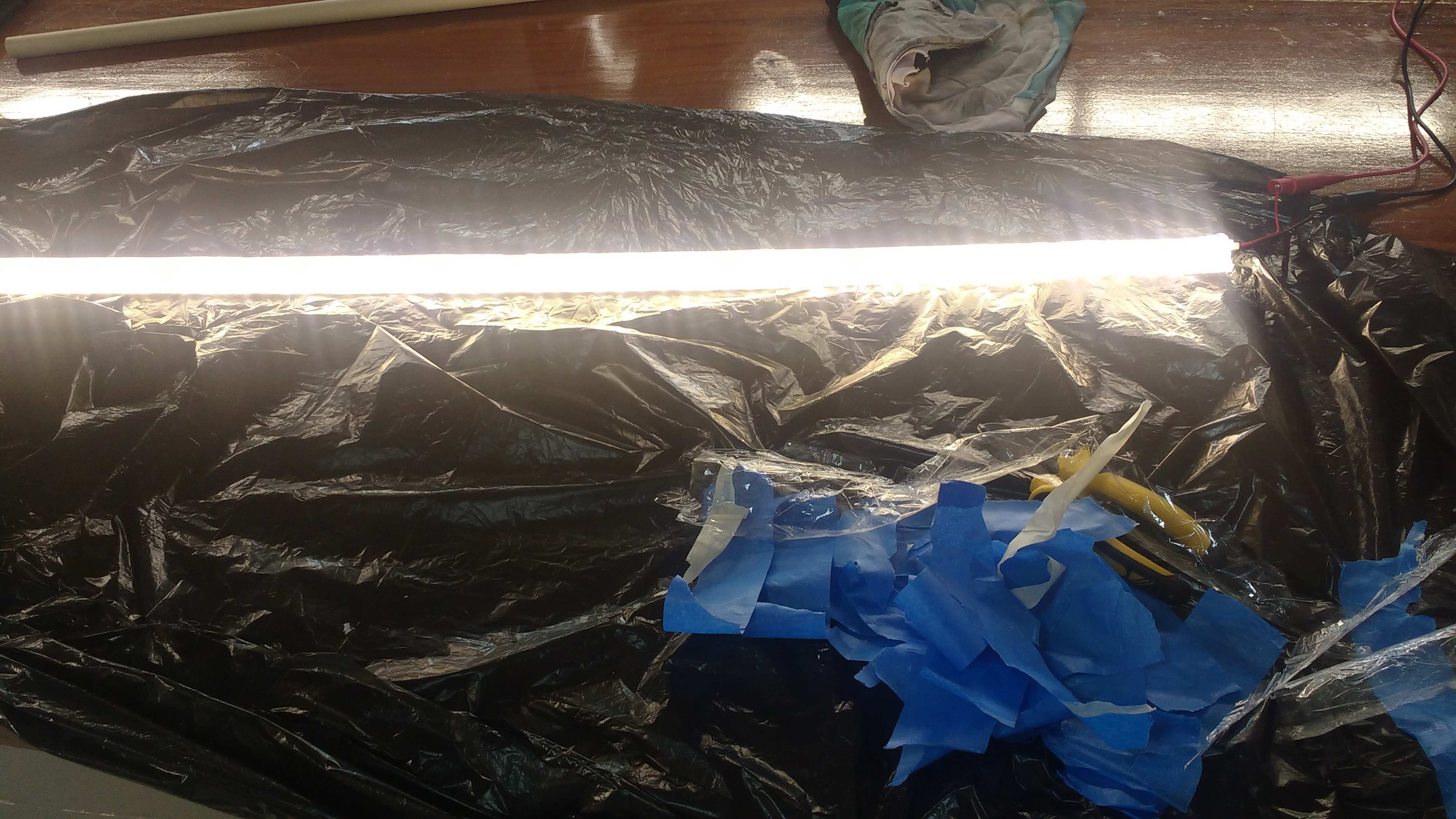
I added a led trip to convert the stick as a light cane. So when all the parts are fixed, I apply resin and form the mold with the film plastic. The next step was to form the cover with another film plastic coverture and apply masking tape to form the final mold.
At time to demold the body, just was neccesary broke the masking tape first and remove the film plastic. And as second step pull down the PVC pipe to get the compo mold free. Once the compo body is free, i probe the led trip with a 12 Vcc Source.
9. The calculation of current consumption estimated around one ampere, but in integration tests will actually see the total consumption.
* UltraSonic sensor 30 mA.
* InfraRed sensor 30 mA.
* Light level Sensor 30 mA.
* Accelerometer Sensor 30 mA.
* Main NemoDuino 100 mA.
* Buzzer output 10 mA.
* Vibration motor 200 mA.
* LedTrip 660 mA.
As total as 1100 mA@12Vcc
At right side a block diagram to plain the initial integration of electronics.
- Mechanical manufacturing.
The mechanical manufacture consists of the elaboration of neb and the handle through 3D printing using ABS plastic. The same for the manufacture of the body with composite resin.
The mechanical manufacture consists of the elaboration of neb and the handle through 3D printing using ABS plastic. The same for the manufacture of the body with composite resin.
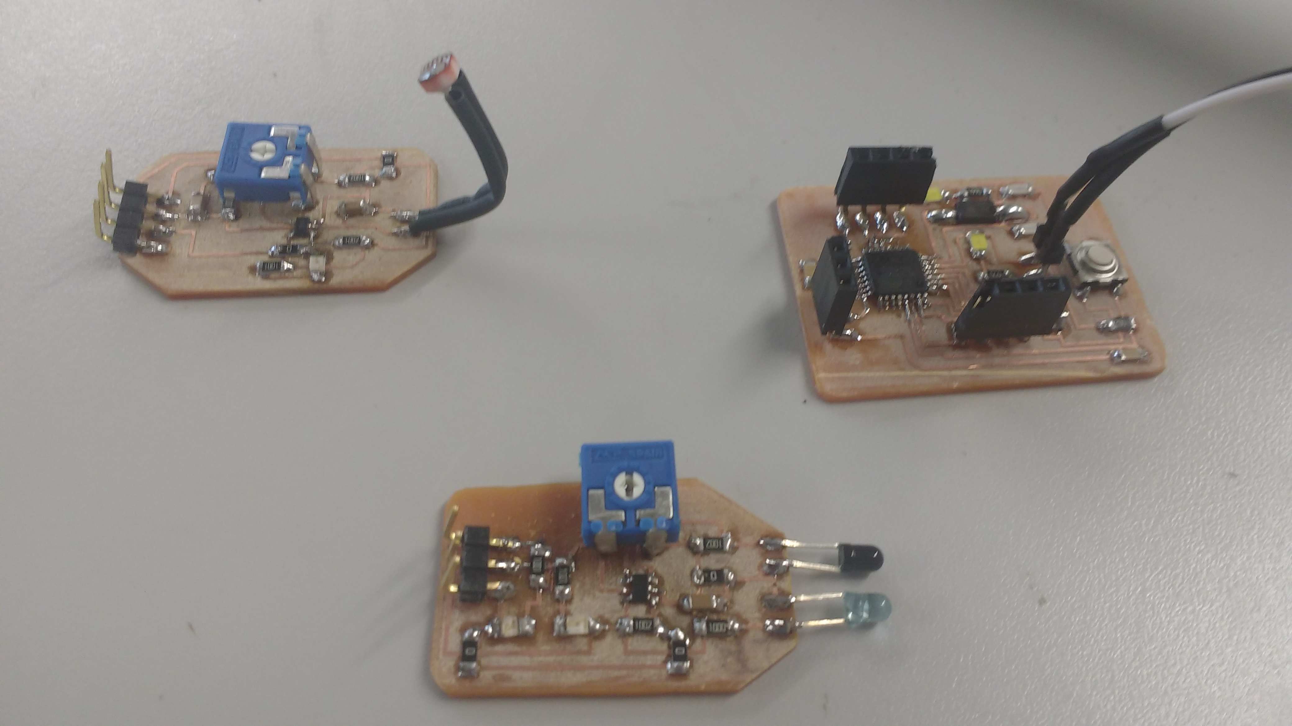
- Electronic manufacture.
This stage involves the design and development of the cards using the knowledge acquired. The boards made are: the power supply, the main processor board, the sensor IR, light, vibration and led trip driver.
This stage involves the design and development of the cards using the knowledge acquired. The boards made are: the power supply, the main processor board, the sensor IR, light, vibration and led trip driver.
A final view for the STL files.