Made a website and described how you did it
Introduce yourself
Described and made a sketch of your final project
Documented steps for uploading files to archive
Pushed to the class archiveDesign and 3D print an object (small, few cm)
that could not be made subtractively
3D scan an object (and optionally print it)
(extra credit: make your own scanner)
Group project: test the design rules for your printer(s)
For 3D printed I tried the Open Scad file from the second week, which is the cone of thread for my final Project.
I used a CUBE PRO 3D Printer, I had to export the file in .SLT so the printer software could read it. Then it is rendered and arrange so it can fit in the tray. In my case because of the size of the object, it has to be put lay down in a 45 degree angle.
A USB is used to load the file on the printer. The tray uses glue so the piece dosen´t move during the printing
Then it processes the file before printing
Then the printer starts building the structure to hold the piece
The file needed eight hours to print so it had to be left overnight. The result:
The support had to be taken off with a cutter.
Results:
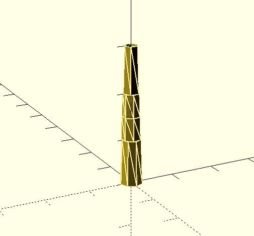
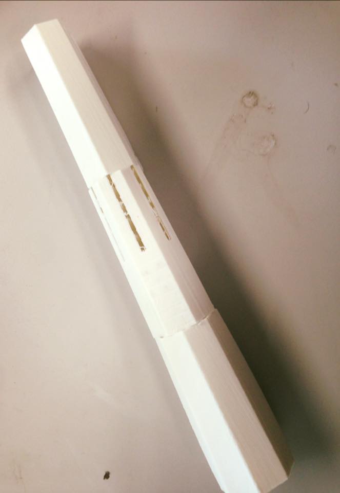
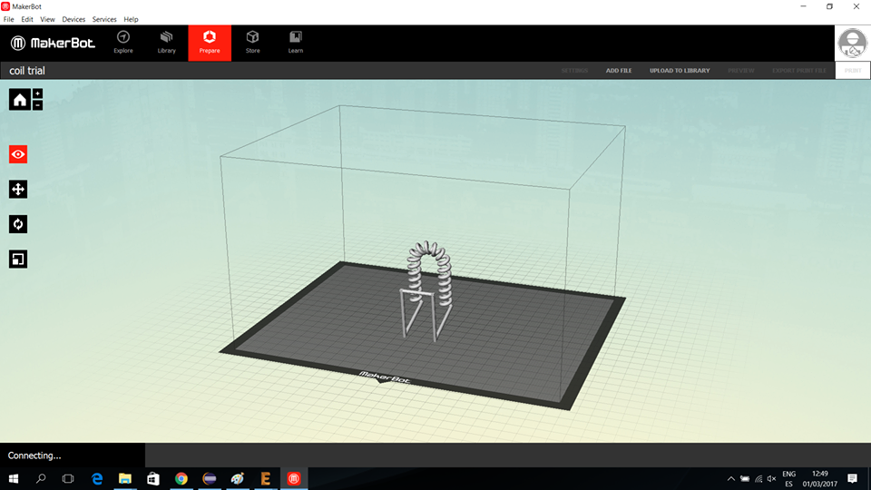
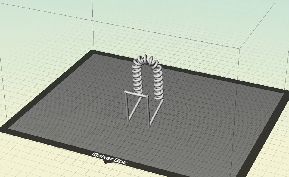
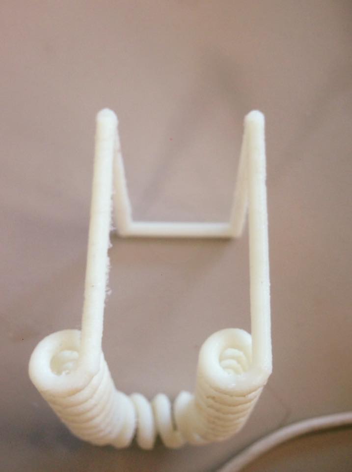
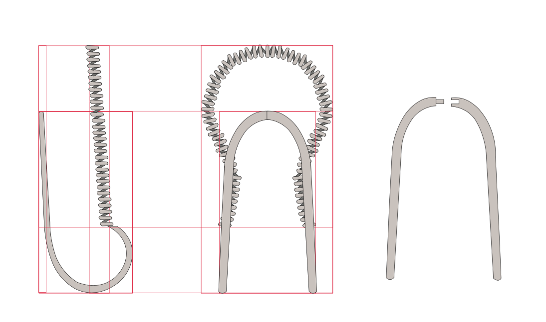
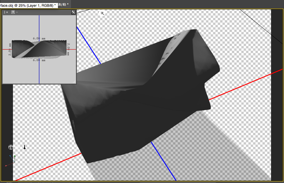
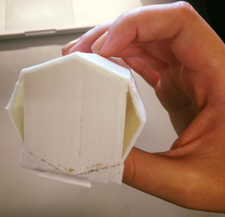
1. It was an Open Scad file, where the image is not as good as in other programs, so at the time of printing I found design problems that I couldn´t see on screen.
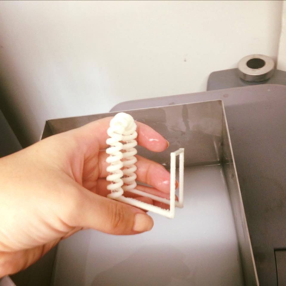
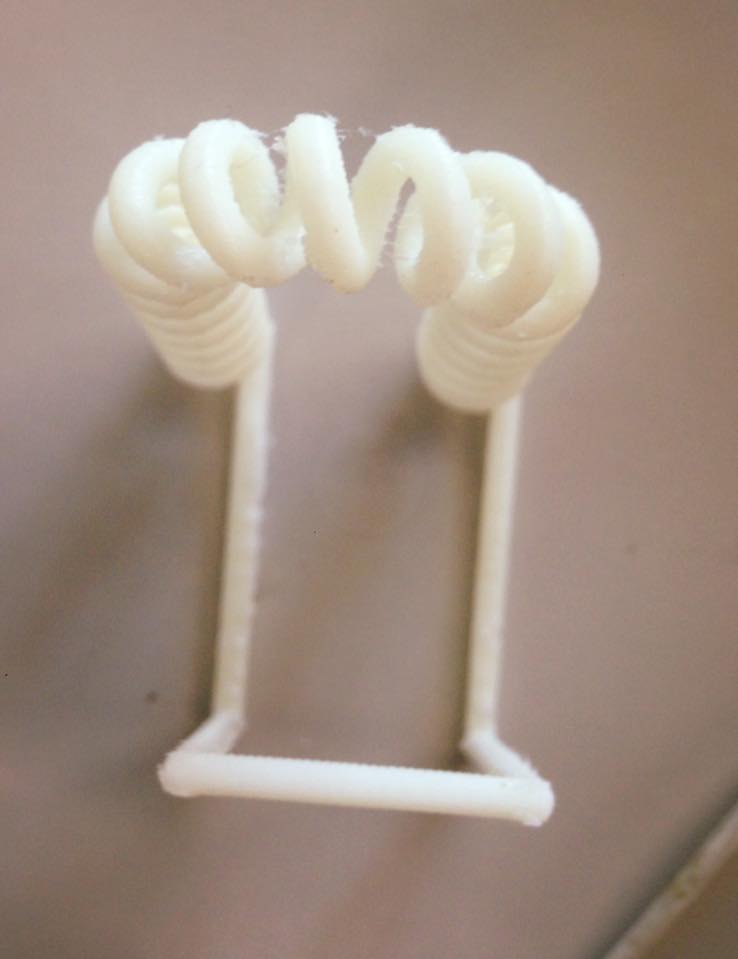
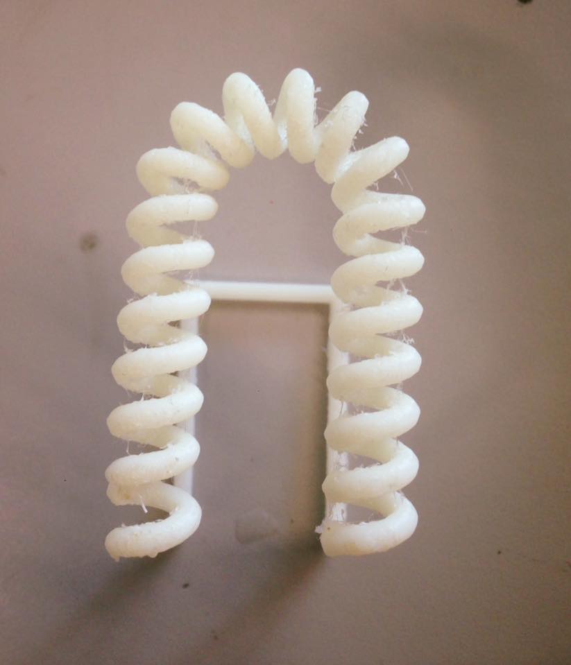
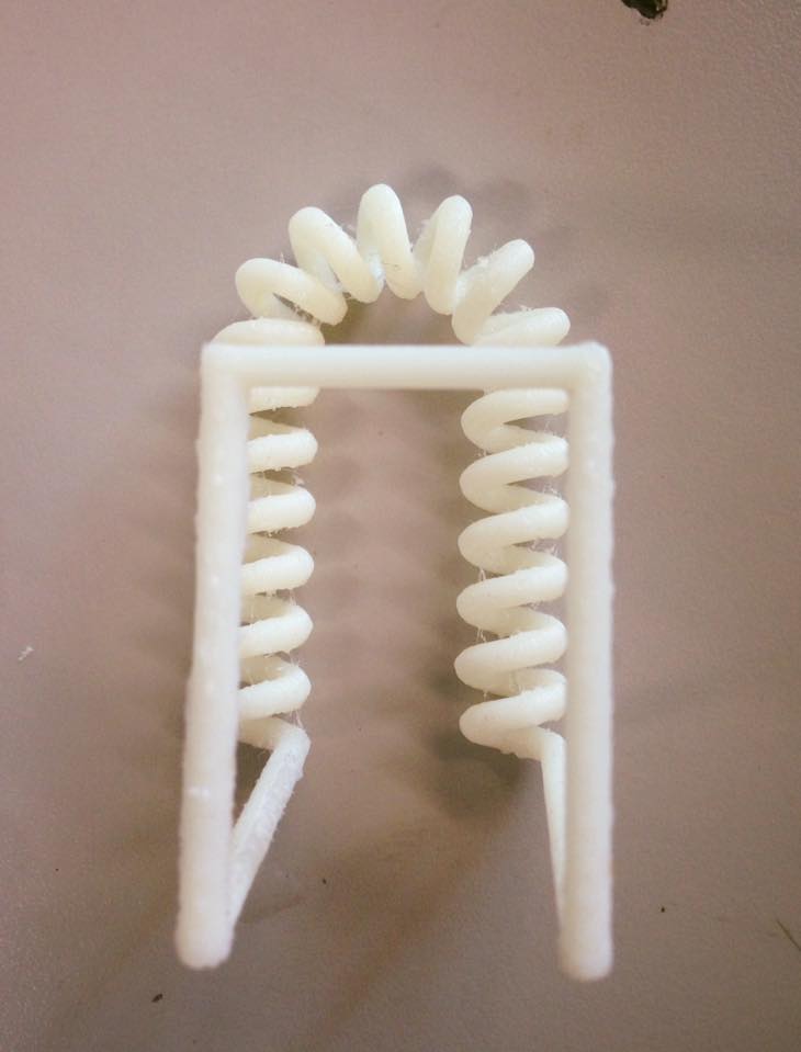
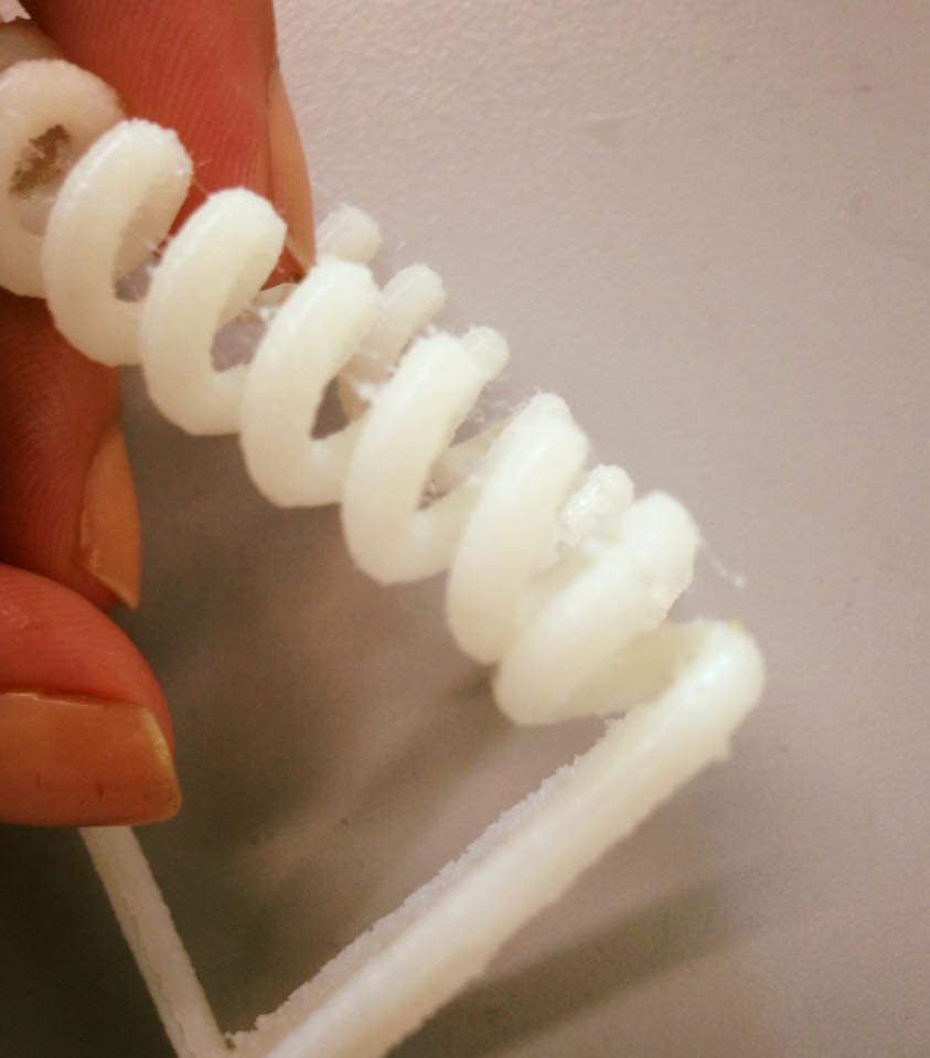
2. In my experience and seeing the work of the other students, the results on the CUBE PRO had more problems than with the other printers. In the parts where there are no support, the material doesn´t attach well.
I wanted to create a modular, Little flexible piece that can be printed and “knitted” First did some designing in illustrator. I started thinking on the basic structure of knitted pieces, then for flexibility I added a spring structure (like in the picture) in some parts and a way to open and close them so you can arrange them in any particular way you want.
I was showing my design in Illustrator to Alejandro
http://archive.fabacademy.org/archives/2017/fablabutec/students/161/
And he did a fast prototype on Inventor so we could see if the idea worked. The file was printed on the Mojo 3D Printer, It took around three hours to print.
Looked like this:
Because the Mojo prints in ABS and creates the support in PVA it has to be washed on the WAVE WASH 55, which looks like a coffee maker machine and dissolves the PVA. It needs warm water and a pill to do the work.
After twelve hours:
About the design, the structure wasn´t strong enough. The corners were weak and the spring broke easily.
Which means, rethinking the design.
The changes are about using more curves to increase flexibility.
(profile view+ front view+ closing system)
I had a meeting with the people of Wolfram https://www.wolframalpha.com
For another Project that we are working on for the university. Wolfram works with mathematics as a coding language. So, for prototyping, they develop a 3D file from a mathematic formula to be printed and see if it was something we could use in the project.
This was printed in the Objetct 30 Prime, on Vero Black, for support it uses a wax that must be removed later as usual.
This is how it looked right out of the printer.
The wax had to be taken off by hand because the machine that makes the work was in maintenance. Actually, I found it to be a very relaxing process
Because in the original 3D file, some parts weren´t together, it broke.
Still a useful experiment.
Results:
For the scanning part of the assignment, I tried scanning a shoe last in the laboratory scanner.
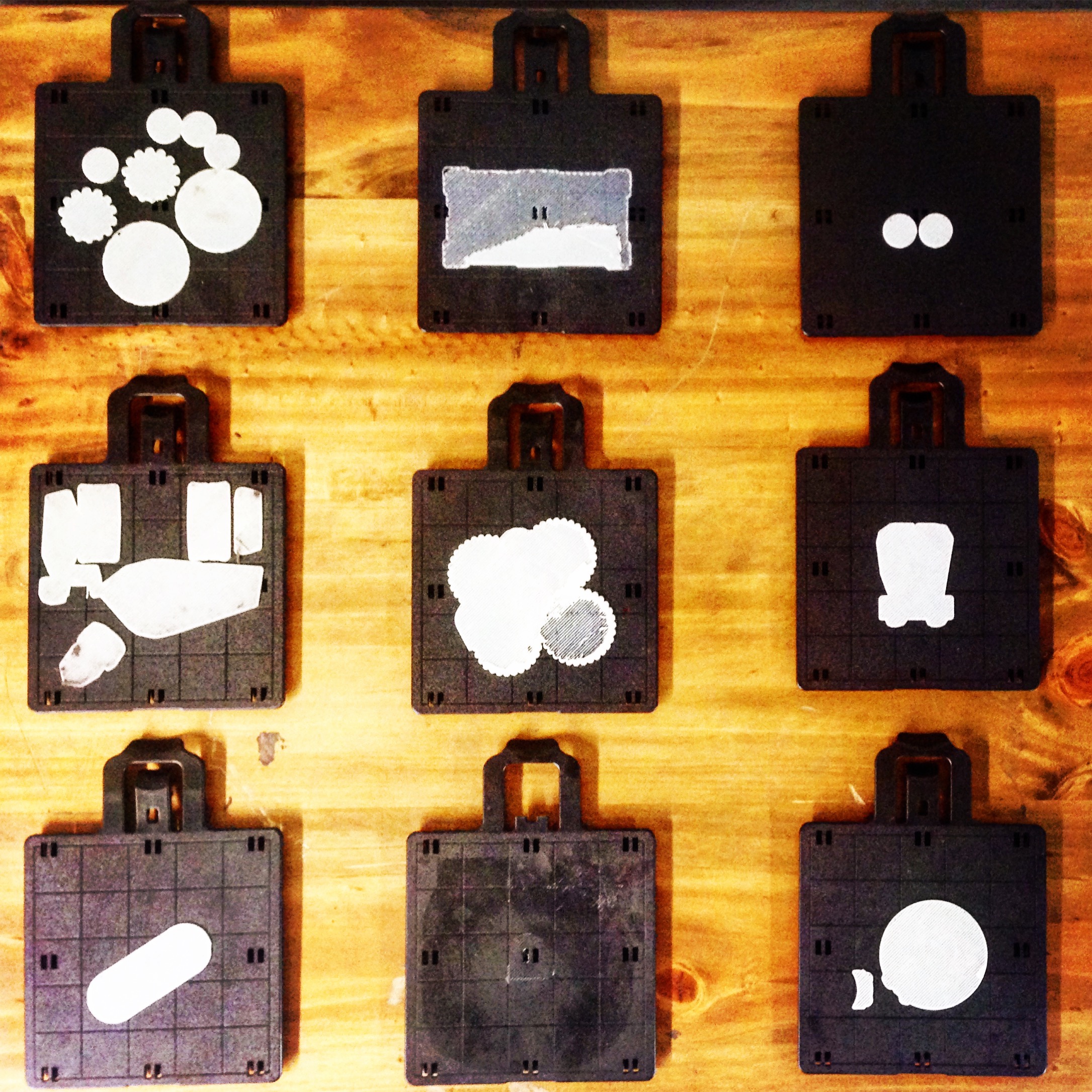
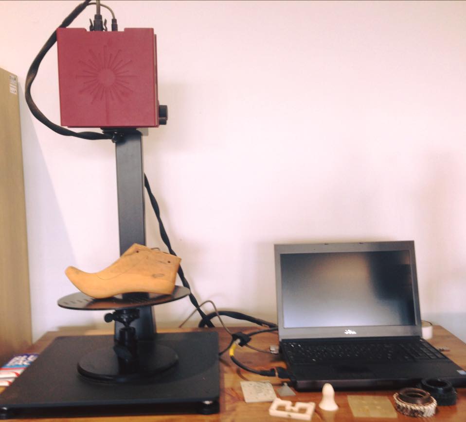
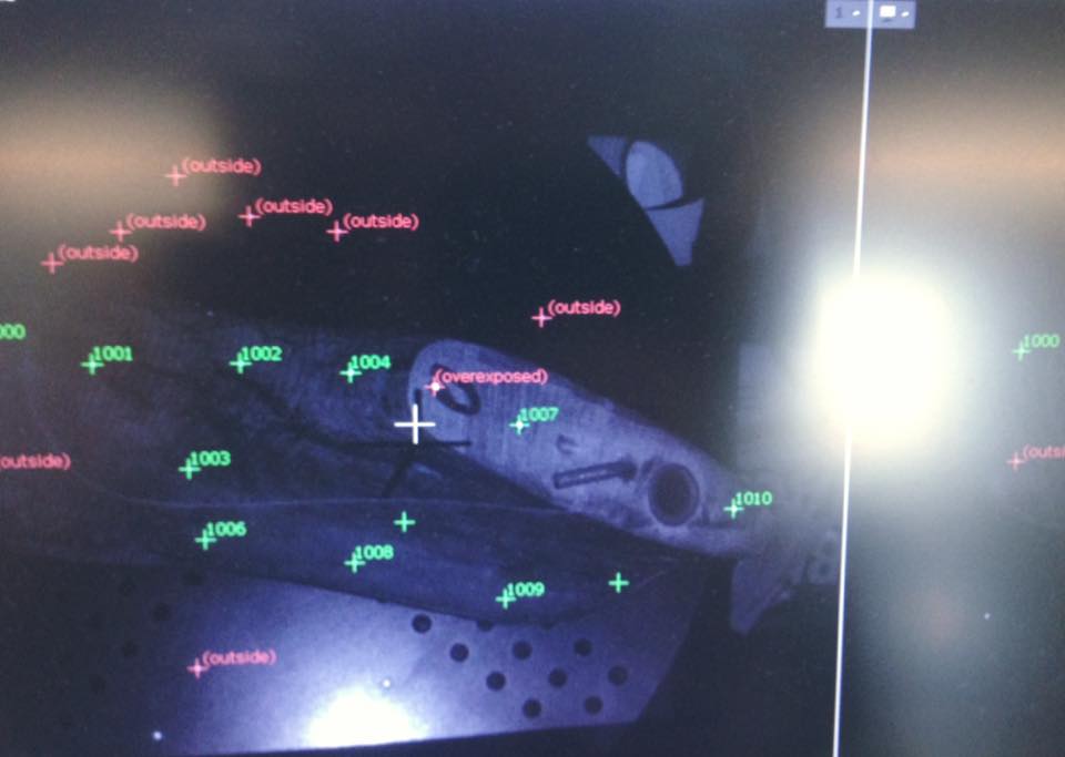
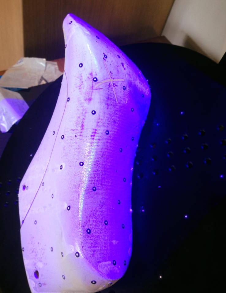
It Works on its own software, for the scanner to work, it needs reference points to read the volume, so black and white stickers must be put considering the form of the object. At the beginning it didn´t read it. Then, it had too many over exposed areas.
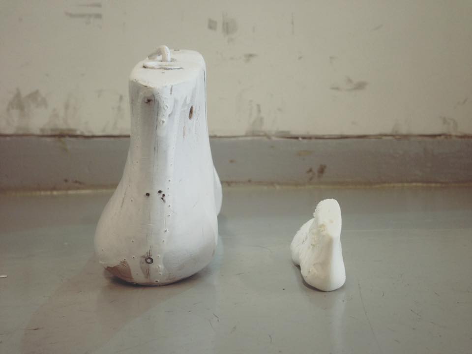
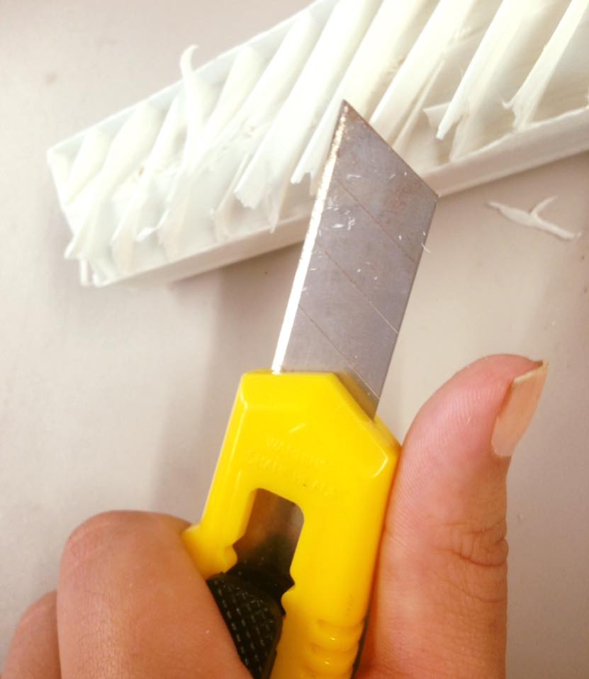
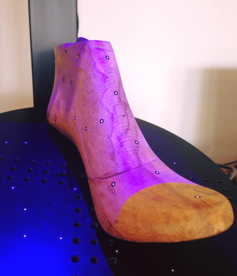
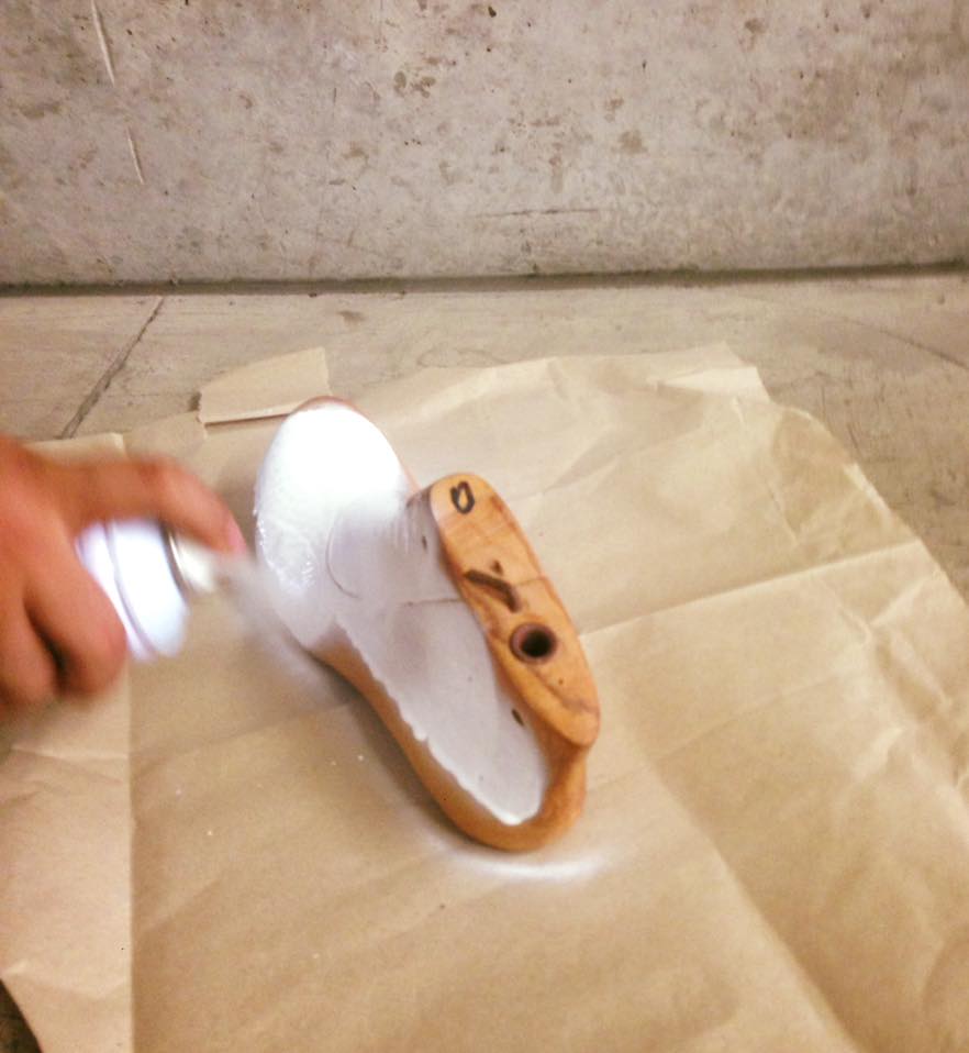
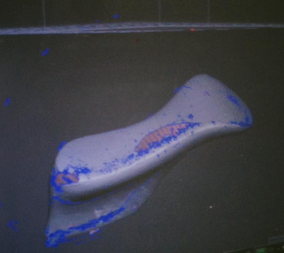
The Wood shoe last was too dark for the scanner, so i tried painting it in white.
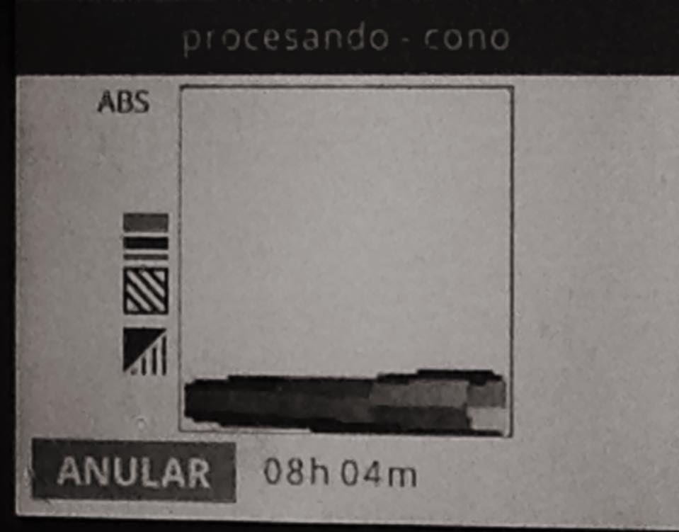
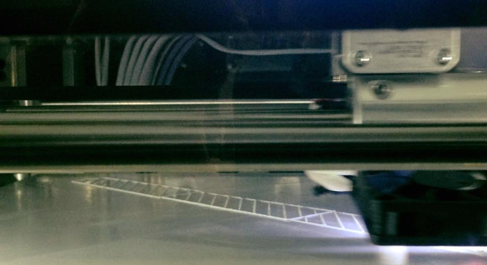
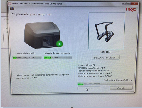
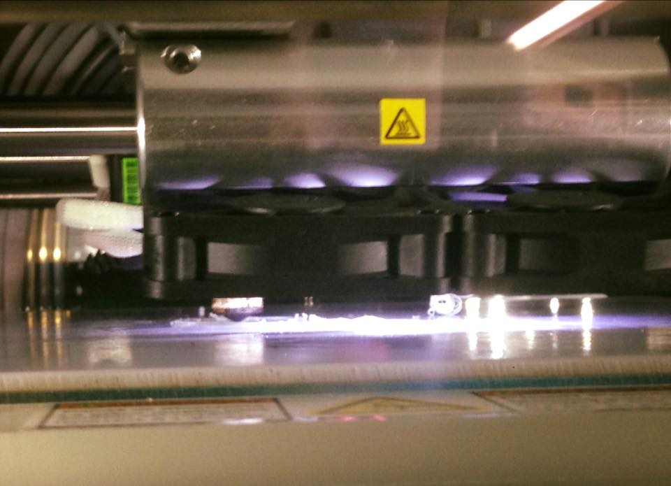
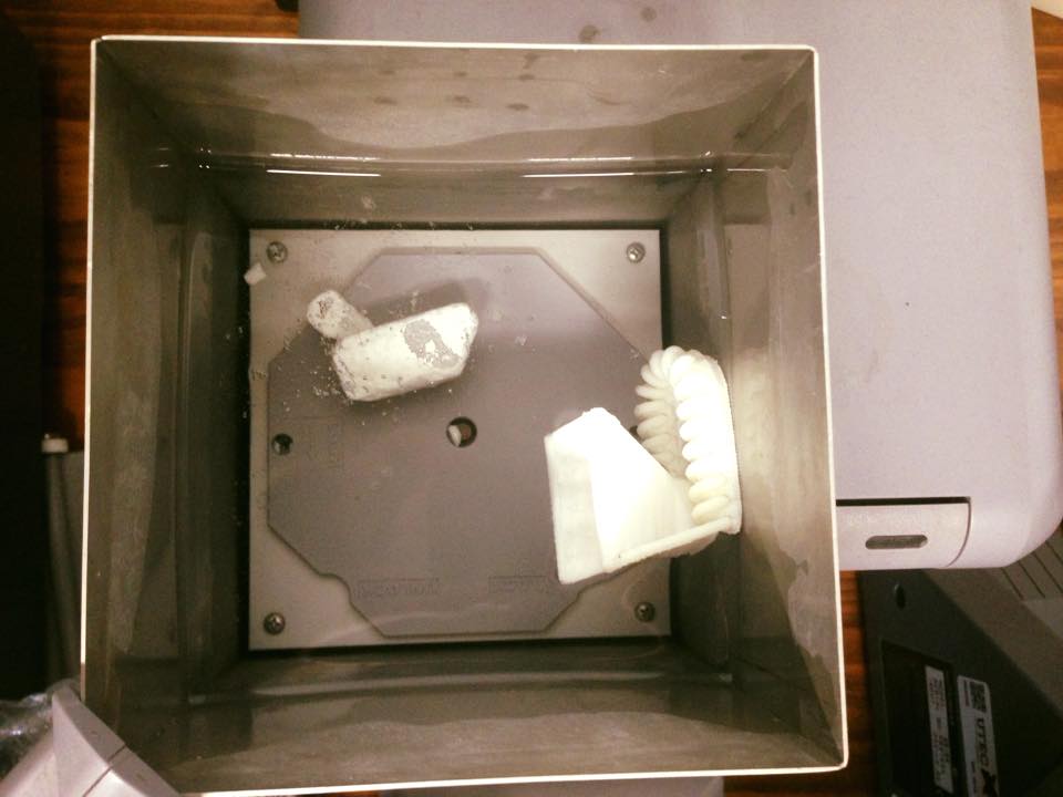
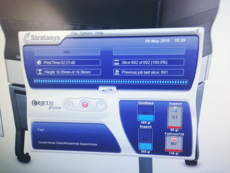
Then the printer starts building the structure to hold the piece.
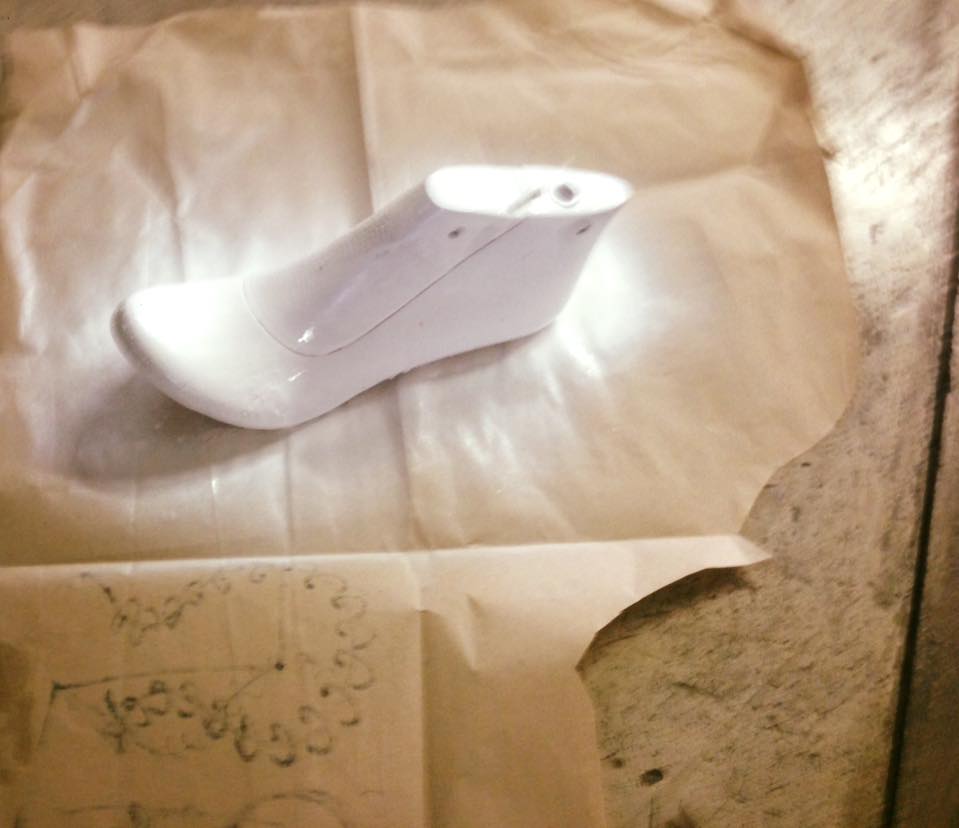
With the piece painted it was much easier for the scanner to recognize it. If someone is going to Paint something to scan later, I recommend mate Paint. The shine of the light on the piece creates overexposed áreas that can be avoided With mate Paint.
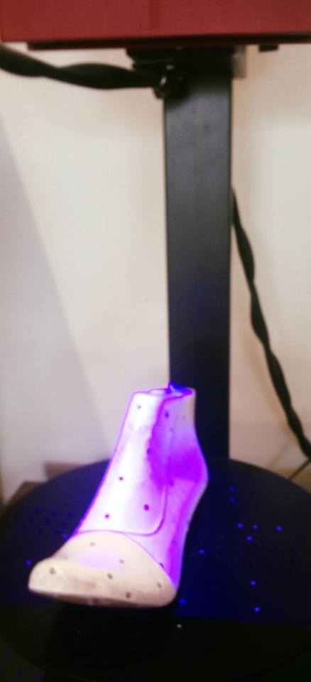
The scanner Works with its own software, GOM SCAN. It works by detecting the reference points (black and white Little circle stickers) and the distance between them.
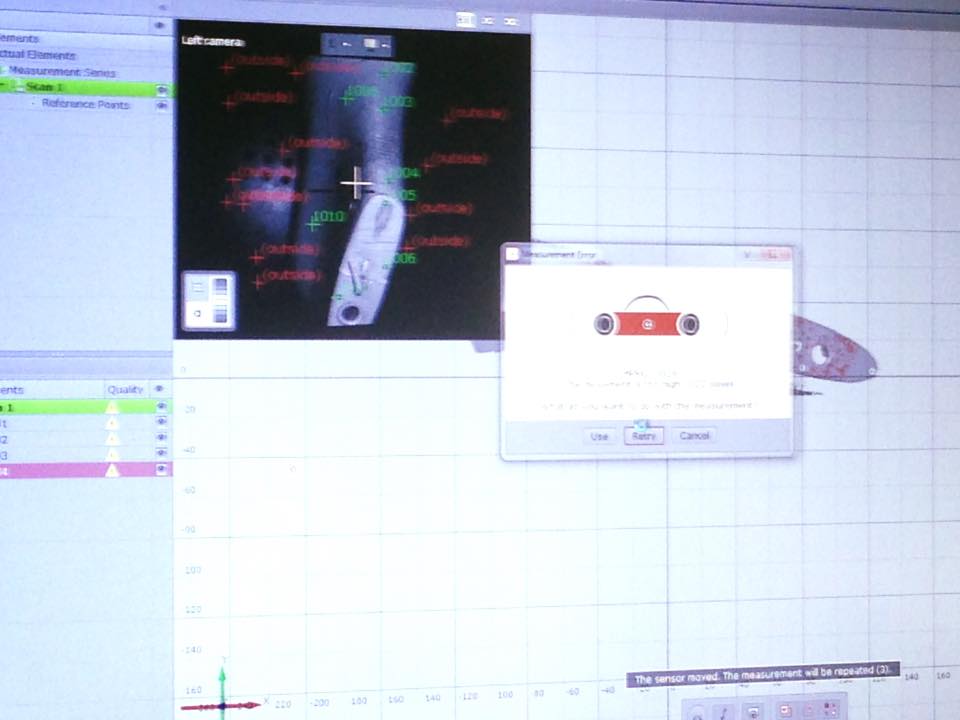
A funny thing was that because the 3D printer was working next to the scanner, it created vibration that messed up the work of the scanner. 
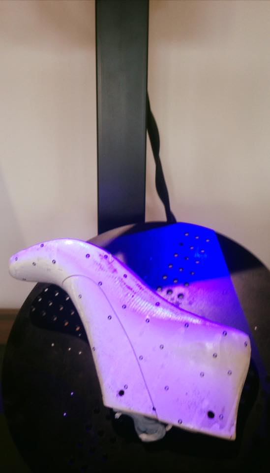
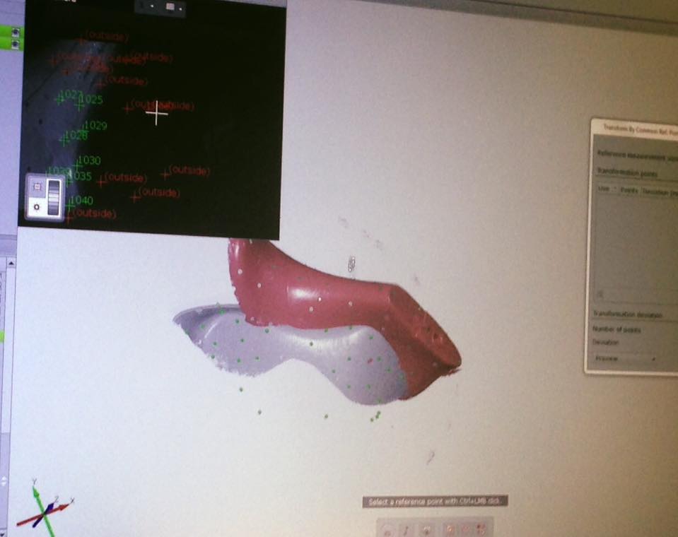
The sole wasn´t painted so the scanner had problems with it. After painting it, a new sequence of pictures had to be made.
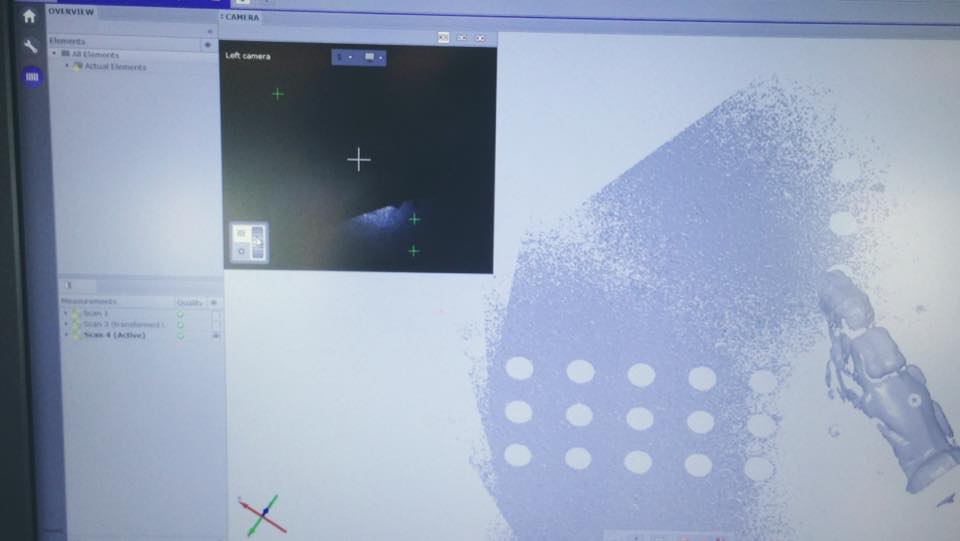
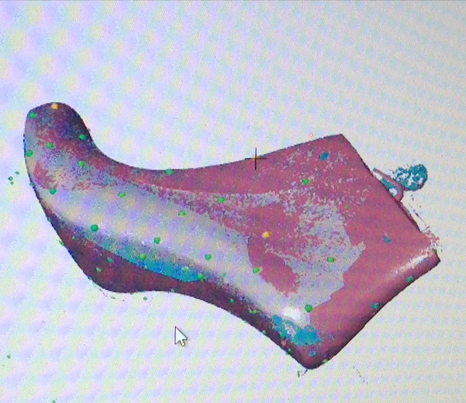
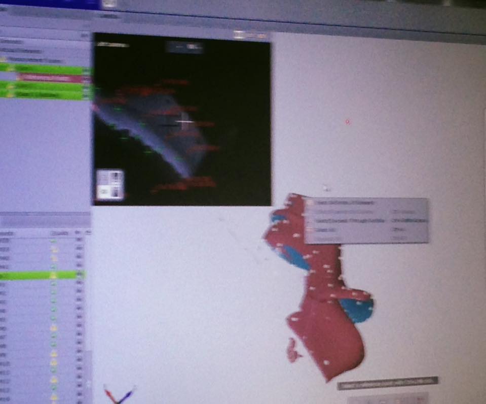
The gray areas are the ones that the ones the scanner is sure about, the red ones, where the scanner is not so sure and the teal is the back or empty parts. The brightest Green are the points of reference.
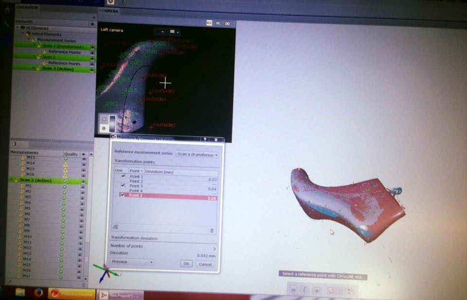
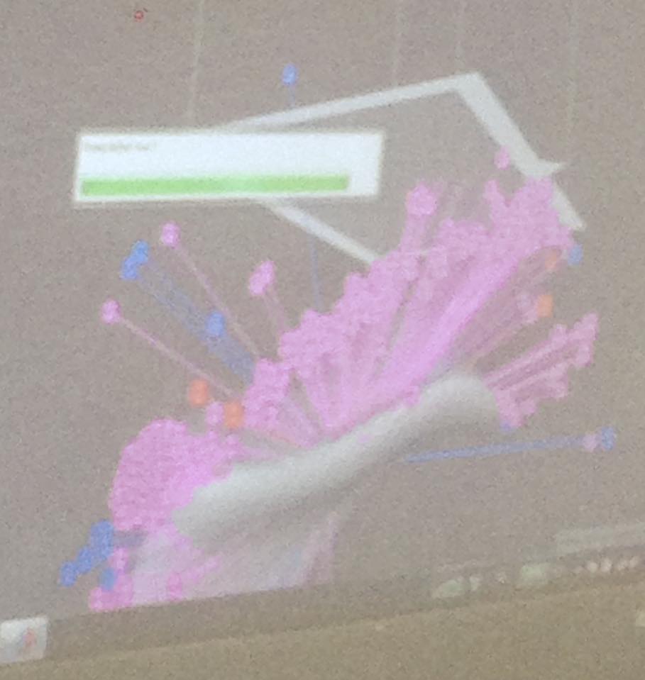
To complete the shoe last three series of pictures to fuse them after.
To do so, you have to detect a few reference points that appear in both views, so the software can know the position the piece must be put in.
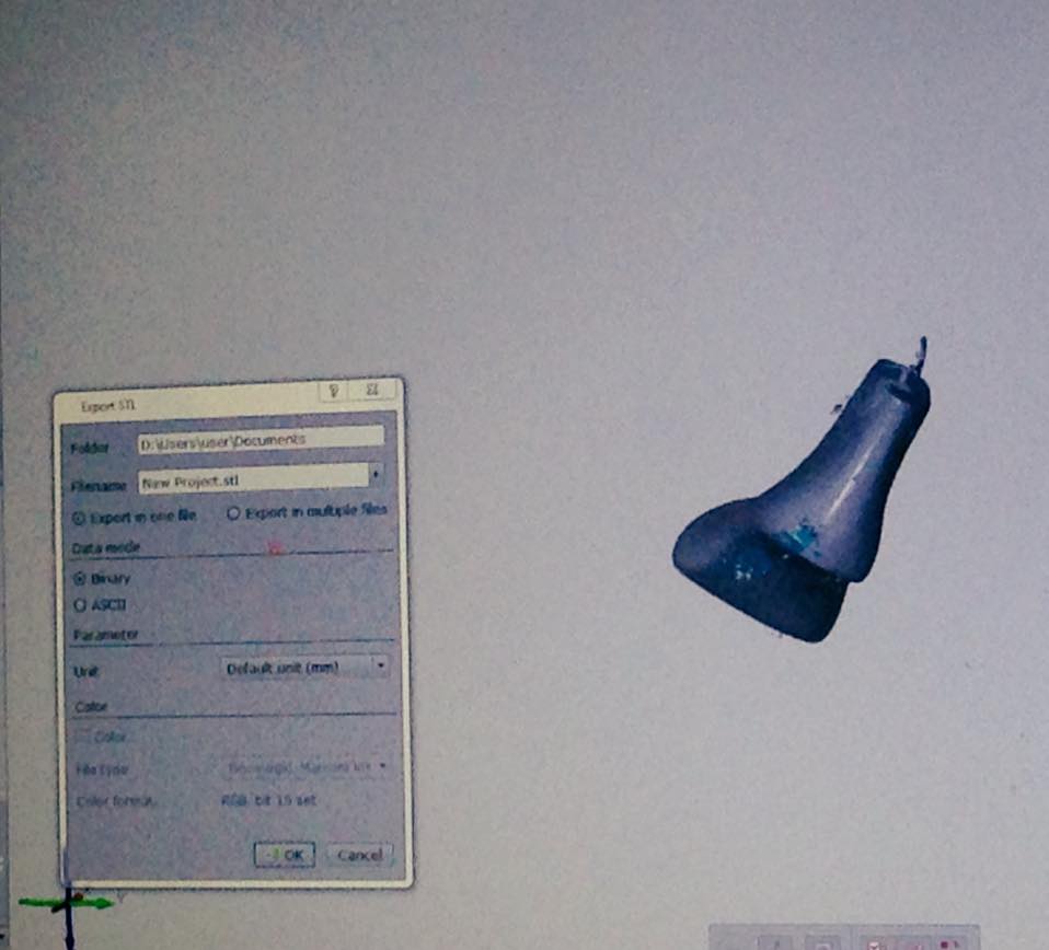
The result :
Almost all the shoe last was scanned. Just a couple holes at the sole and the low part of the ankle.
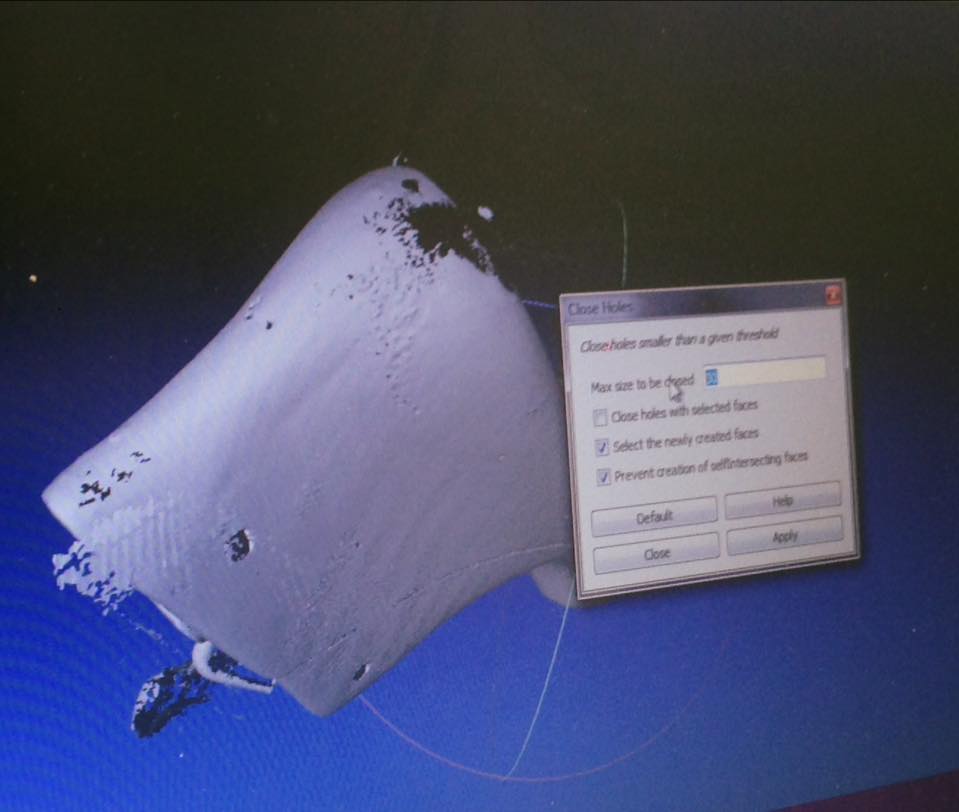
Then, I went to Mesh Lab, to reduce the quantity of polygons to 250 000.
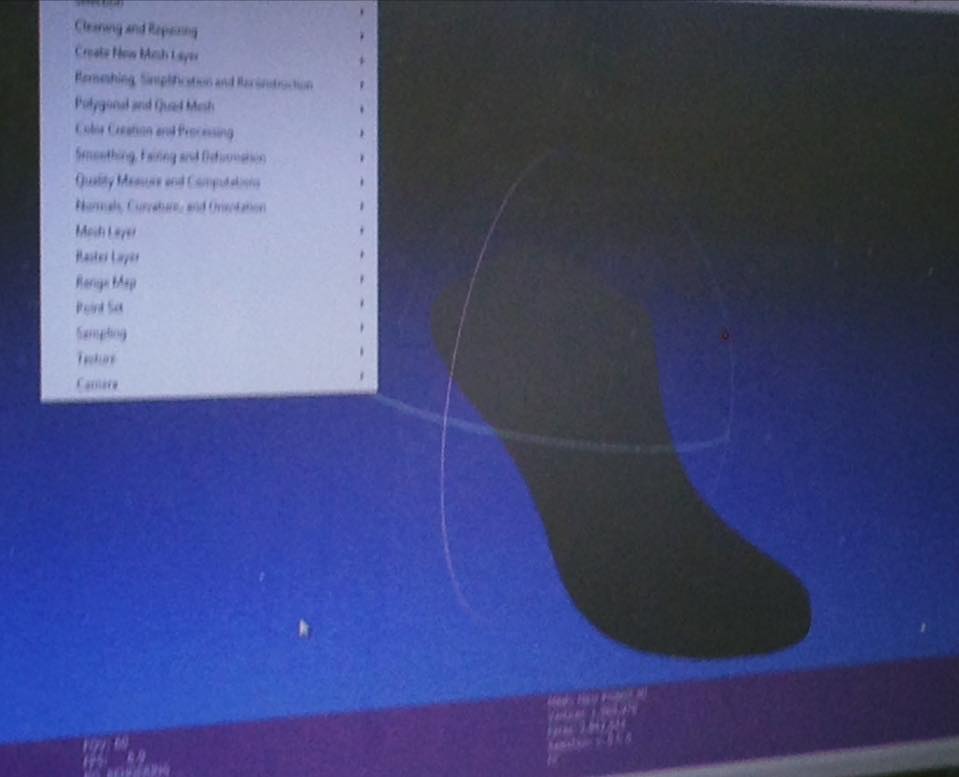
Next step, Mesh Mixer to repair and delete extra information.
And once again to Mesh Lab to fill the holes.
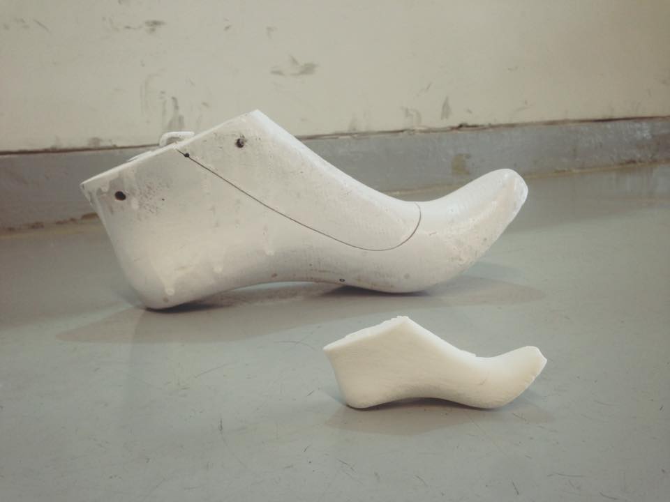
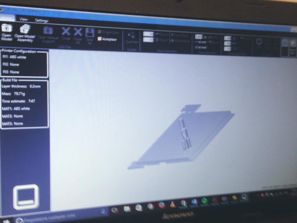
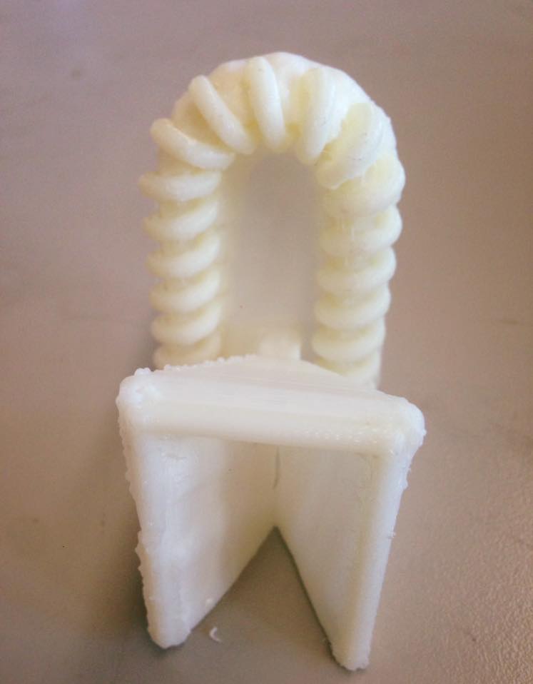
Finally, sent to print in the Cube Pro at 30% of the real size.
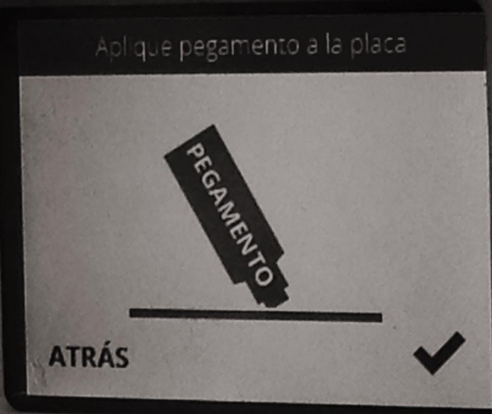
Using the same procedure first explained in the Thread Cone exercise.
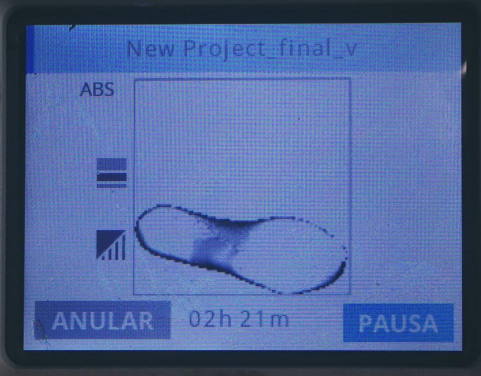
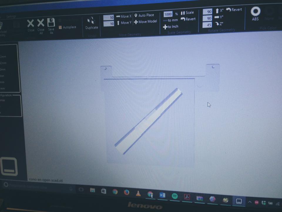
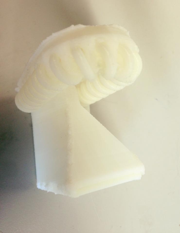
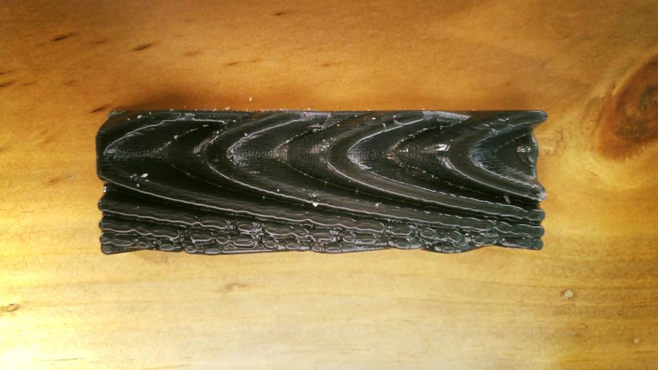
Results:
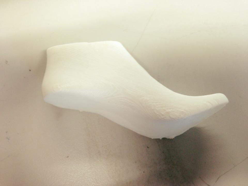
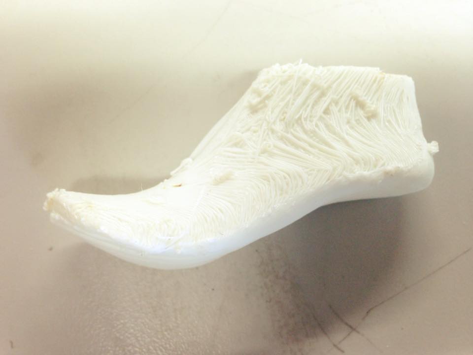
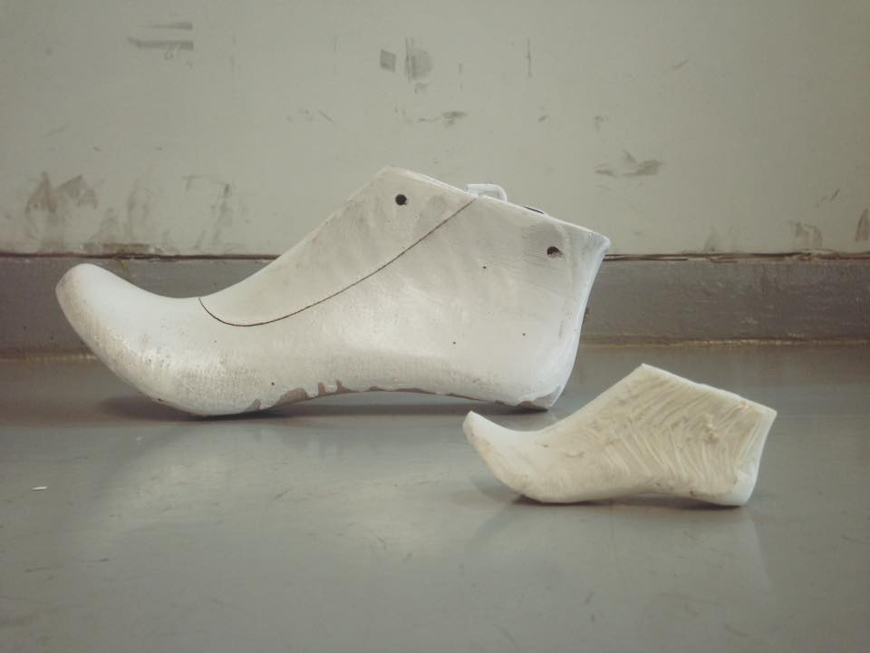
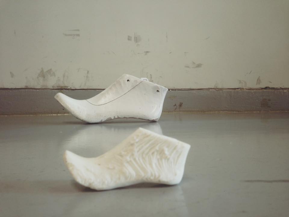
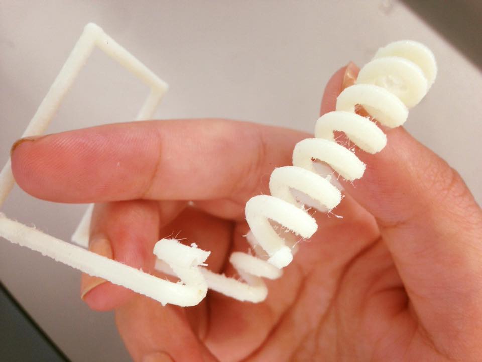
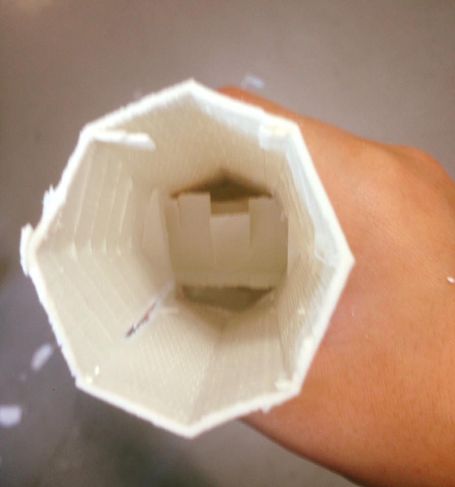
But the other side had some problems.
s
This was the side that goes to rest on the tray.
Comparison: