3D Printing
Addictive manufacturing is also known as rapid prototyping. We add materials by layers, thus building up the model. Since its build by layers, we can produce any complex designs. The 3D printers in our FabLab are Ultimaker 2 and Dimension.
Subtractive manufacturing is a process where removal of material is done to produce the required model.
We use a large chunk/block of the material, and the machine starts to remove the unwanted material from the block, thus building down the model. It is difficult to build complex designs via subtractive, because the machine tool might not be able to remove materials from an enclosed design. The machine for subtractive process thats available in our FabLab is the Roland Modella MDX-20 with the necessary cutting tool.
Machine Description and Setup


There are two 3D printers in our FabLab, Dimension SST 1200es and Ultimaker 2. I used only Ultimaker, so I will try to explain it in detail.
"Dimension 3D Printers use ABS thermoplastic to build the models. Model and soluble support materials come in convenient enclosed cartridges that are a snap to load. Inside the 3D printer, plastic filament travels through a tube to the print head, where it's heated to a semi-liquid state and extruded in thin, accurate layers. The modelling bases provide a stable platform where your prototype builds. Once printing is done, you simply take the recyclable, flexible plastic base out of your 3D printer and snap off the model." The support material is soluble, thus we can get much accurate and cleaner models.
Ultimaker 2 is a Fused Filament Fabrication desktop 3D printer, uses PLA thermoplastic to create the models. It utilizes open filament system which allows us to create our models from a variety of different types of filament. I read in wiki, its possible to print using acrylonitrile butadiene styrene (ABS) and polylactic acid (PLA) and other thermoplastics such as Nylon and Acrylic (PMMA), but that is not recommended.
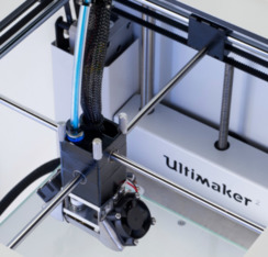
The filament is fed into the Ultimaker from the back using a stepper motor. It moves straight into the print head. The print head has a 0.4 mm nozzle which heats up the filament and melts it down through it. The nozzle has temperature range from 180°C - 260°C. The recommended thickness for the filament is 2.85 mm. The layer resolution is up to 20 microns with print speed ranging from 30 mm - 300 mm/s and travel speed ranging from 30 mm - 350 mm/s. The print head can move in X-Y directions; for the Z axis, the base plate moves along. The base plate also heats up and has temperature range of 50°C - 100°C . The print head has a couple of cooling fans to cool down the layers that are formed. It gets activated automatically after creating the first layer.

Cura is a 3D Printing Slicing software used for converting the .stl files to .gcode format which is the format hunderstood by Ultimaker. Cura supports STL, 3MF and OBJ file formats. This software generates an estimate of time required to print the model and allows to set the type of support structure the model design needs and other settings such as temperature control, print head speed, travel speed etc. The converted .gcode can be directly saved into the sd card. The software is available for Windows, Linux and MacOs. I downloaded the mac version.

The memory card slot is the only means to transfer our design files. Later versions allow wifi transfer. The control wheel is used to select the different options and settings from the menu. Click Print -> Select File Name . Done. Our designs would start materializing.
Testing the limitations of the 3D printer
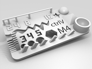

We got the design to for testing from thingiverse. The test results are
The overall size of the baseplate was okay
5mm circle -> 4.67 mm
4mm circle -> 3.7mm
3mm circle -> 2.6 mm
M4 Nut size visually looked fine
The smoothness of pyramide, cone, all numbers was good
The rounded print, wave and half sphere was good
The minimum distance and walls of 0.1/0.2/0.3/0.4/0.5/0.6/0.7mm had minor defects
The bridge print of 2/4/8/16/mm was fine
Overhang of 25°/30°/35°/40°/45° have some cracks
All the flat parts were visually good
Designing
This week's assignment is to 3D print a design that could not be materialized using a subtractive method. I decided to 3D print a hinge, which I could possibly use for my final project.
I used Rhinoceros for designing this. This design is an iteration over my week 2 design done on Onshape.
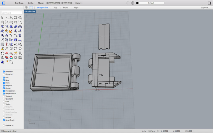
The above image is my relatively final design ( It keeps on changing.. !! ) . The hinge section is what we could not build via subtractive method.
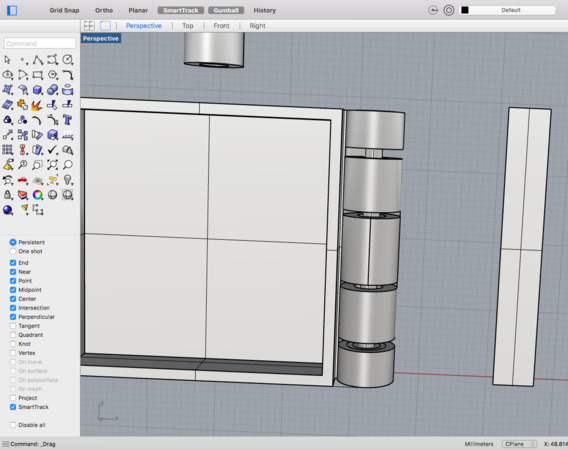
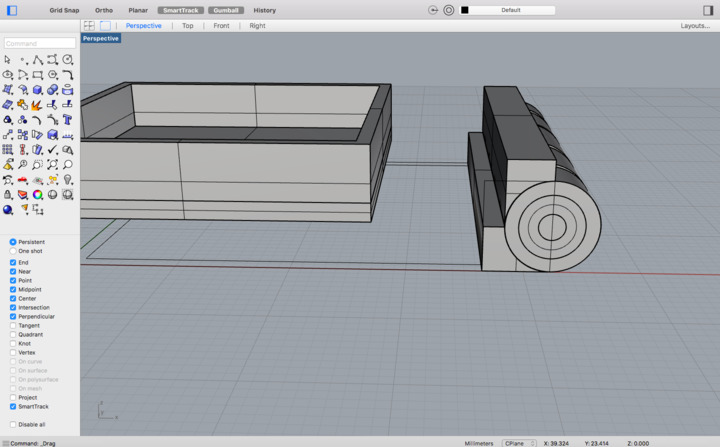
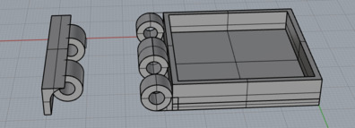
When the 2 part hinge sections are combined. Note the center rod that runs through the parts which is connected permanently to one part of the hinge. This design can rotate at angles upto a bit greater than 180 deg. By subtractive method, its very difficult to create the cylinders and the nearly impossible to create the connecting rod, the inner part of the cylinder shell about which the hinge rotates.
Following is a gif of screenshots I took when working on this design.


Some of the commands I used were, ExtrudeCrv, BooleanSplit, BooleanDifference, BooleanIntersection, Trim, Cap. Used Circle tool, Rectangle corner to corner tool, Polyline tool. Thats about everything I used for this design. I used the Linear Dimension tool also to make sure I dont forget the dimensions of the design.

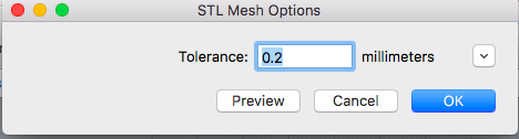
I selected only the hinge part and exported it using Export Selected in STL format with 0.2 mm tolerance.
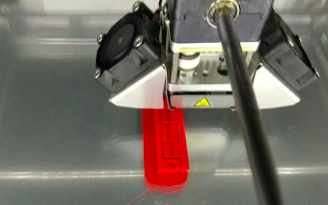
Opened the file in Cura and saved it into the sd card. Then initiated 3D printing.
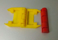
My 3D printed hinge.

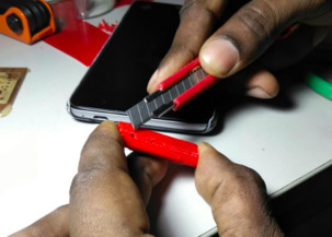
Later I updated the design further and scaled it down as well. This is because the allowance I provided for rotation, made the design move freely whereas I wanted the design to be a bit tight.

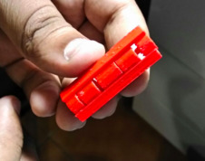
Got it printed, Hero Shot
Challenges faced
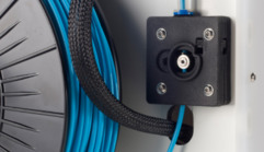
When the print was initiated the material wasnt extruding properly. The material clotted within the nozzle. We pulled the filament off after reversing the spool and cut off the clotted portion.

After fixing back the filament, forwarding the filament wasn't working properly.


We pulled off the filament all the way from the back and found the step motor that forwards it up, ran and shaved off the filament. We cut off that portion and fed it back, and forwarded the filament. Then extruding ran fine.
Original design files
Hinge.stl
HingeConnectors.stl
HUDcase.3dm