Input with mic
So this week, I wanted to use mic as an input; so checked our lab inventory for an amplifier build-in microphone, but there was only electret. So I decided to replicate the mic project provided by Neil with the schedule.
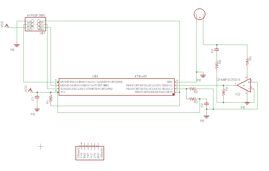
I went through the board design Neil has done, and tried to draw the schematic from it. I used Eagle to draw the schematic and the board design.
I encountered a lot of problems with my design and I'll be explaining what all went wrong.
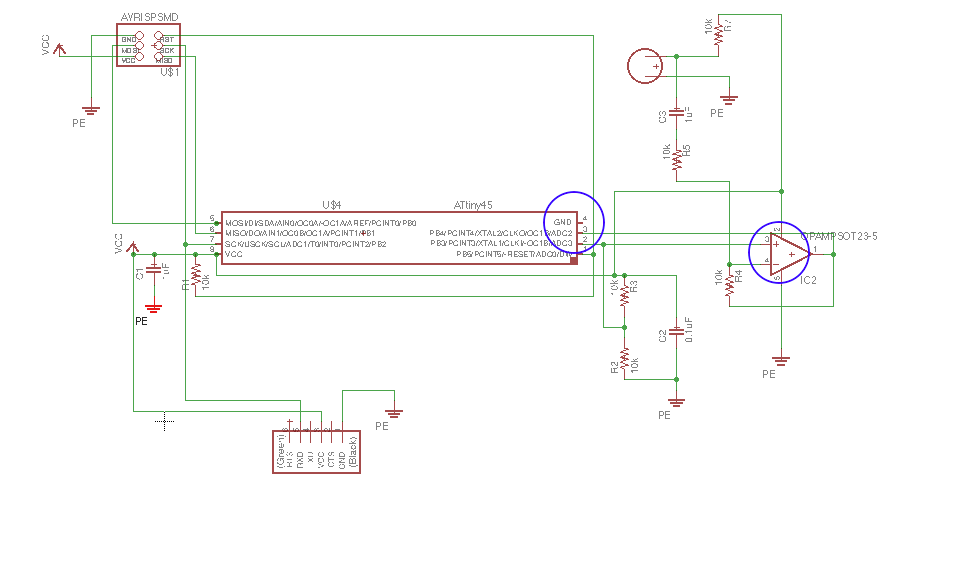
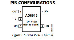
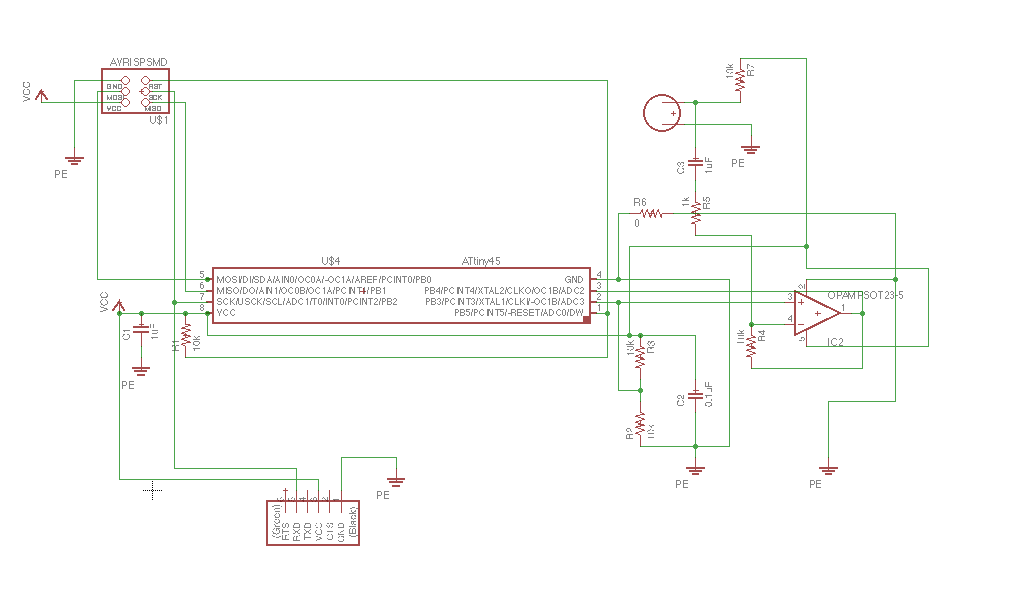
The following picture is a screenshot when I was working on the schematic and it went on to look like the next picture. See the blue circles that are marked. Those happen to be the couple of mistakes I did not notice and went on to use this design. I took me a while to even notice this mistake, esp forgetting to ground the IC. The other mistake was with the opamp connection, I read the pinouts of the opamp and figured out that pin 2 should be grounded and pin 5 is to be connected with Vcc. But me.. no these things dont matter to me.. I connected pin 5 to ground and the other to vcc even when I took time to figure these things out.
Opamp datasheet
Having made these kind of mistakes early on and failing to notice these, the rest of the story is a tragic failure. :D
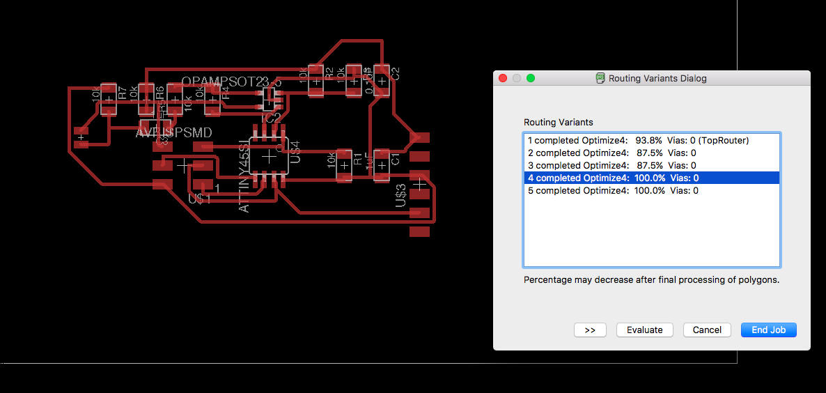
Board designing using Eagle
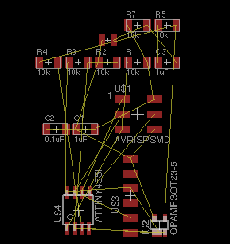

Rearranging the components,

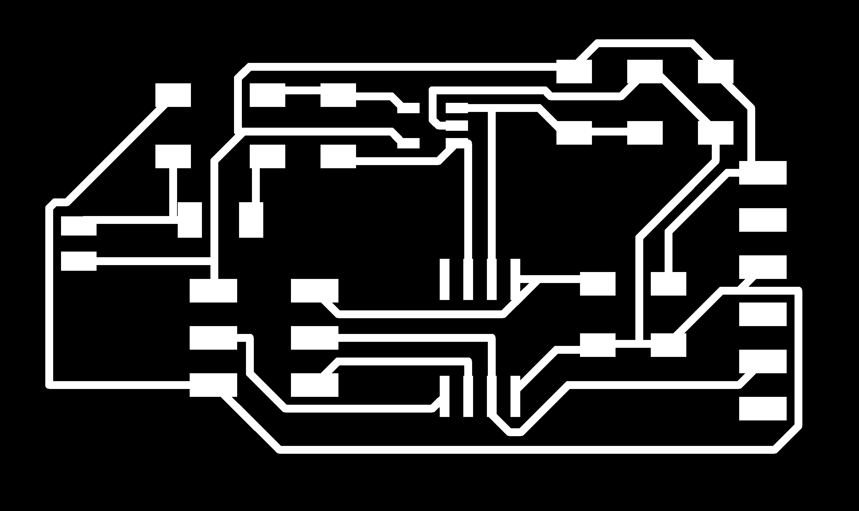
Took the traces and cut pngs,

Milling the board

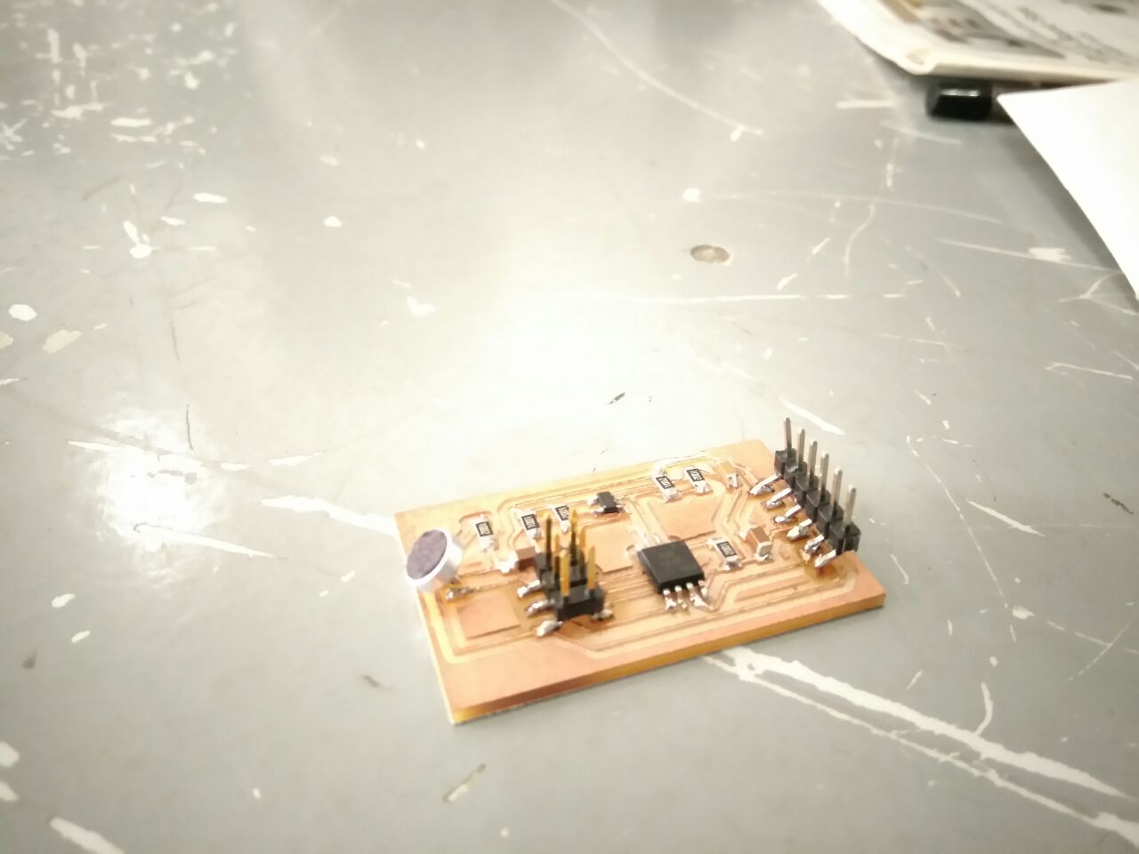
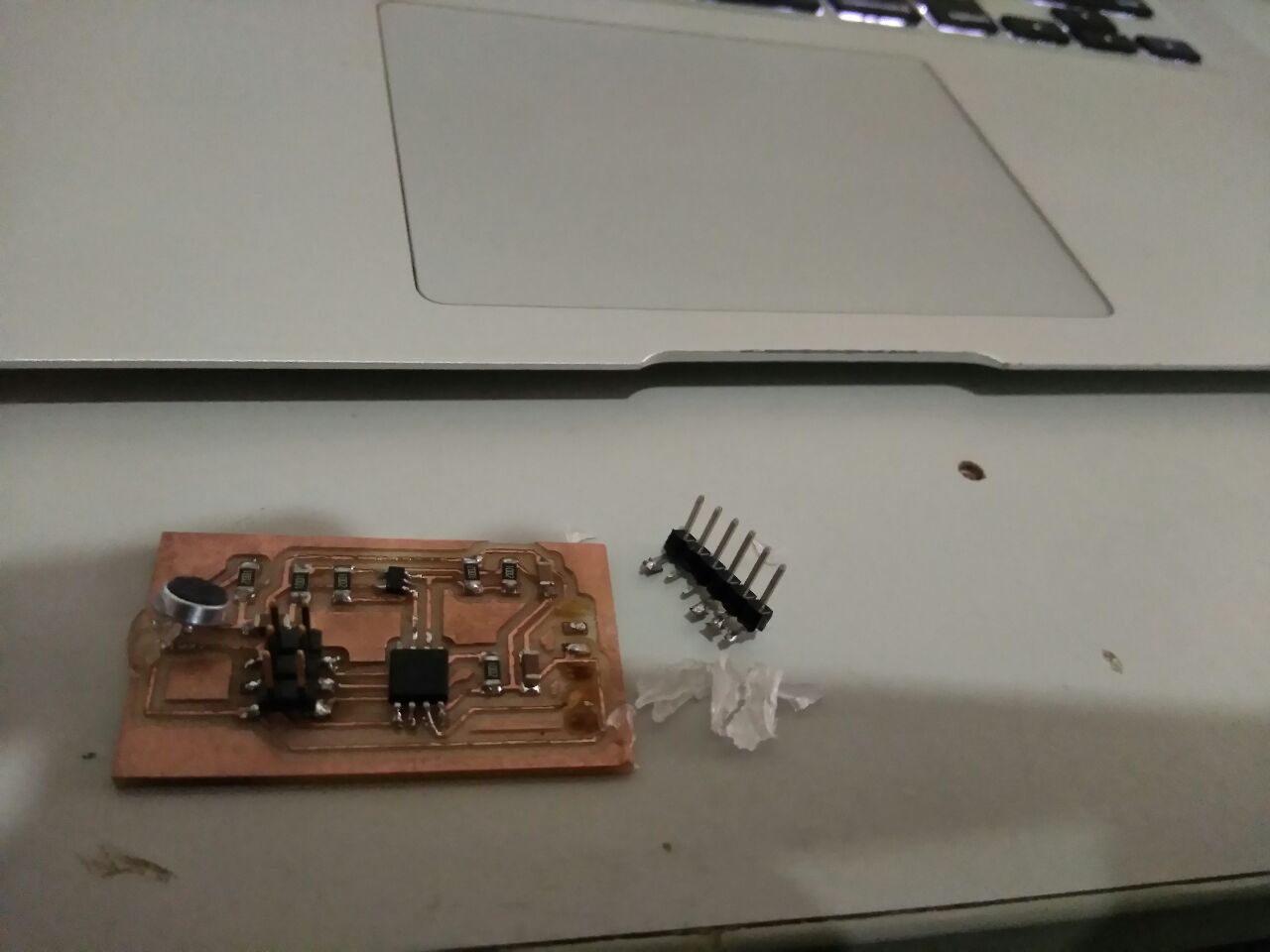
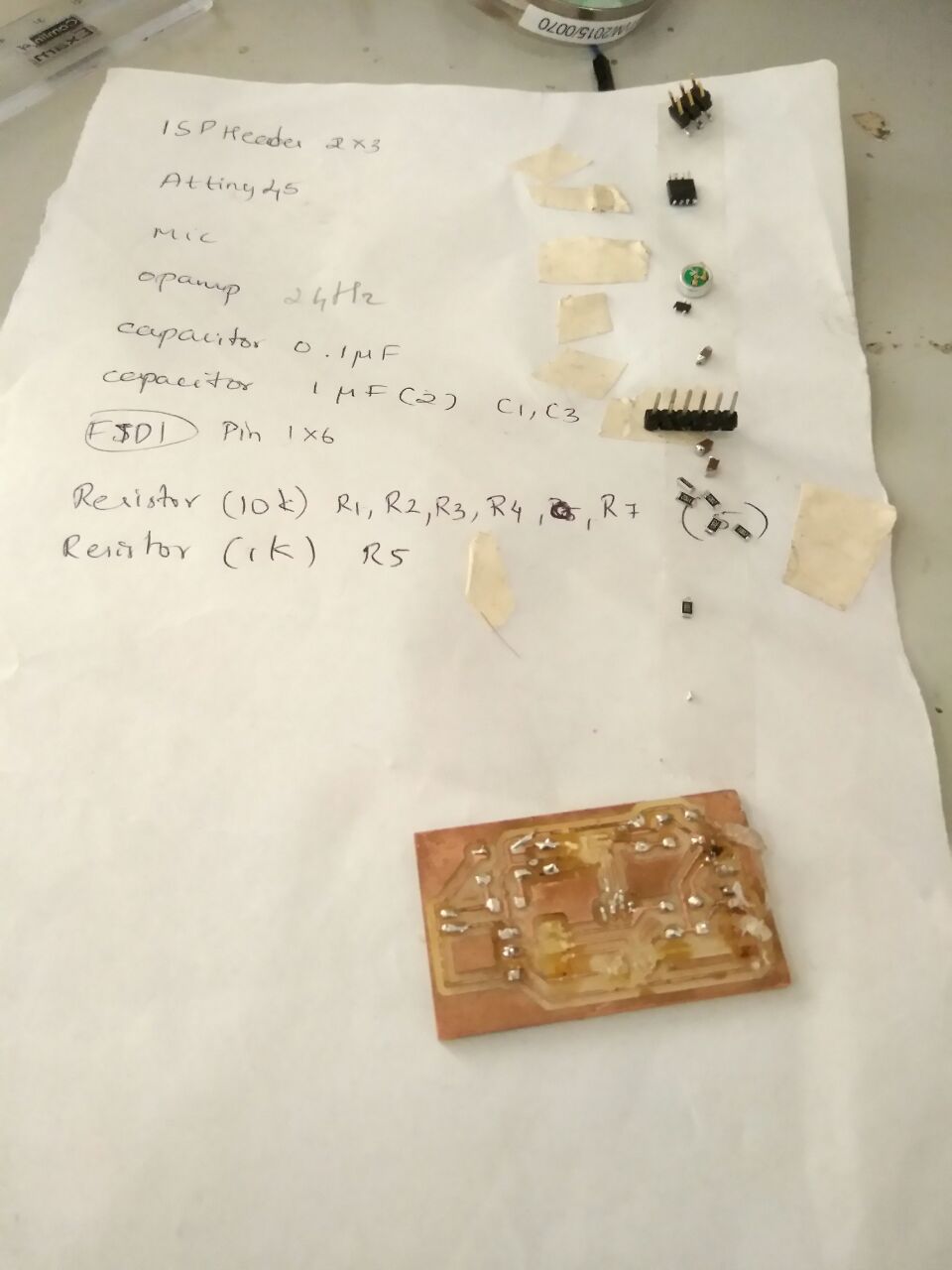
After Assembling the components
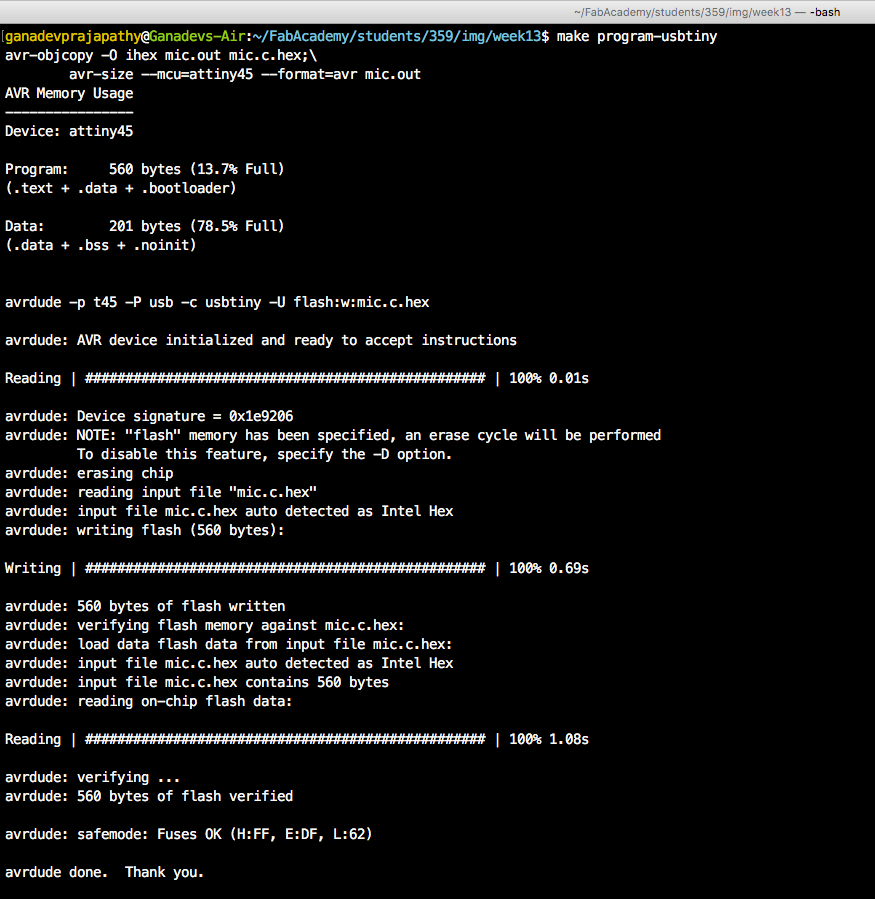
Programming Attiny45
I used Neil's code itself to test the board,
Debugging
Then the FTDI pins completely came off when I was debugging,
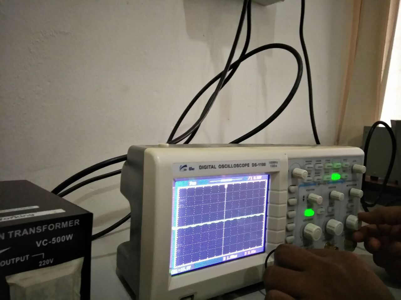
I found out that there was no output from the opamp when I connected it to the oscilloscope. Thats how I figured out I connected my opamp the wrong way.
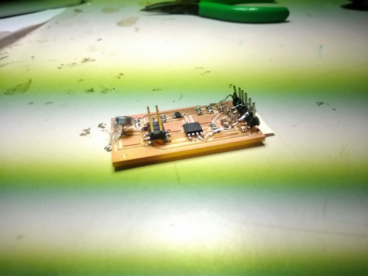
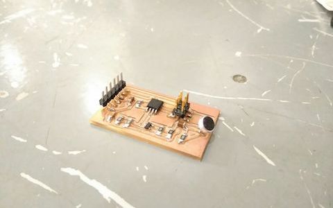
A picture of the board after resoldering and using jumper wires to fix the opamp issue,
There was still some shorts beneath the ICs which I was unable to fix, so I decided to redo everything, after having figured out what all went wrong.
The schematic diagram
The board design

After milling

There was some traces not cut properly, so I manually cut it. It was probably with the settings I chose for milling. (Lot of mistakes this week..!!)
Disassembling the components
Removed all the components from the older board
Reassembling the components
Applied hot glue as well on the pins,
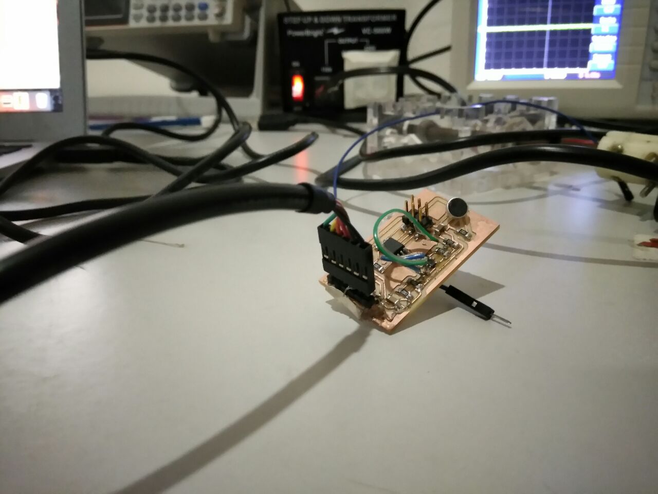
Programmed the board
Output from the opamp
I was able to get the output on the python GUI Neil provided. But the signal strength was in range with only milli Volts. So I am of the conclusion that the opamp was not working properly or that I might have damaged it.
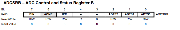
I used the following screenshots to figure out the code from Neil.
Attiny45 Datasheet, mic.c, mic.py


To run the python GUI,

I failed to take any screenshots when the GUI showed the output, because the opamp wasnt amplifying the input, but was infact outputing the input. Now my output kind of looks like this after I tried to debug why the opamp was not amplifying,

I also logged what was I receiving from the serial connection,

Update
In networking and communication week, I was able to fix the issue; I problem as I earlier pointed out, was with the opamp. After replacing it with a new one, I was able to receive output from it.

Design Files
Inputs.sch
Inputs.brd