Interface and Application Programming
This week is about the interface and application programming and the assignment for the week is to write an application that interfaces with an input and/or output device that we have made, and exploring as many tool options as possible.
My Plan
My plan for this week is to explore the different tools Neil mentioned and then try to make a android interface to interact with the board I have made before. I have chosen the mobile platform due to its wide spread use. I intend to use a bluetooth module for this assignment to speak to the board and the phone.
Bluetooth module HC-05
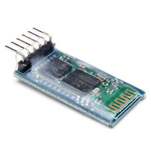
HC-05 module is an easy to use Bluetooth SPP (Serial Port Protocol) module, designed for transparent wireless serial connection setup. There is lot of information regarding the pinouts and usage in the internet, and few useful links are itead.cc/HC-05 and developer.mbed.
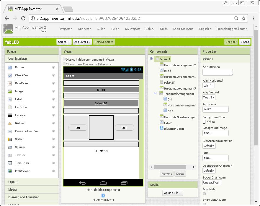
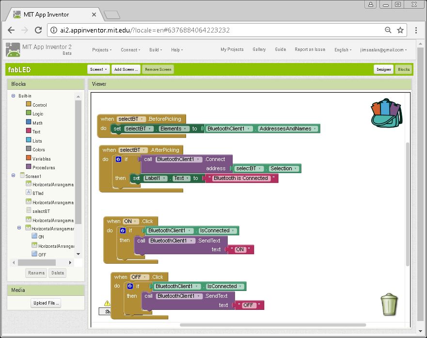
MIT appinventor
App Inventor is a free, cloud-based service that can be accessed using a web browser. The apps made using the app inventor could be tested on the android phone using the companion app. There are a good amount of learning content available like the ones as beginner-videos, app inventor tutorials, unofficial introduction. Also to use the bluetooth on app inventor, there are numerous resouces available like the one on, App inventor bluetooth.
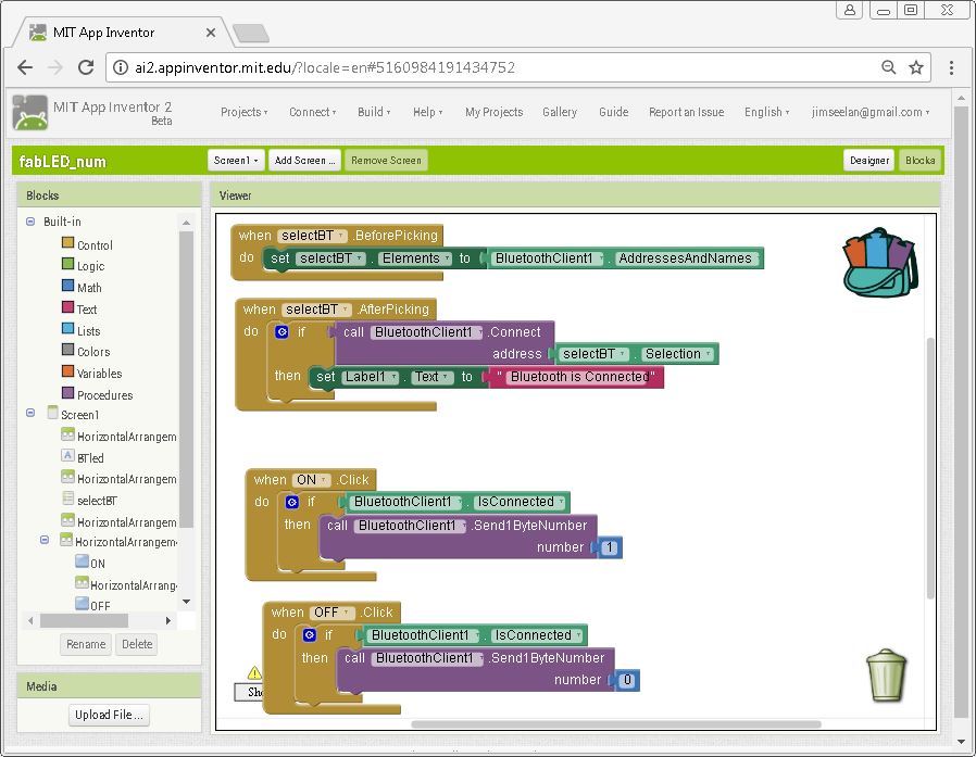
I created an app by going through the various tutorials, the Design and the blocks screen are shown in the images below.
The Initial testing using Arduino
I first tried programming on a Arduino, and then tried proramming on the attiny44 board created before. I have chosen Arduino for the initial tryouts as there are numerous tutorials and instructions available on the internet. I have went through and tried few of the intructables and tutorials, and finally found this instructable, which I have referenced hugely for the code.
Code used on the Arduino
String voice;
void setup() {
pinMode(13, OUTPUT);
Serial.begin(9600);
}
void loop() {
while (Serial.available())
{
delay(10);
char c = Serial.read();
voice += c;
}
if (voice.length() > 0)
{
Serial.println(voice);
if(voice == "ON")
{
 digitalWrite(13, HIGH);
}
if(voice == "OFF")
{
 digitalWrite(13, LOW);
}
voice="";
}
}
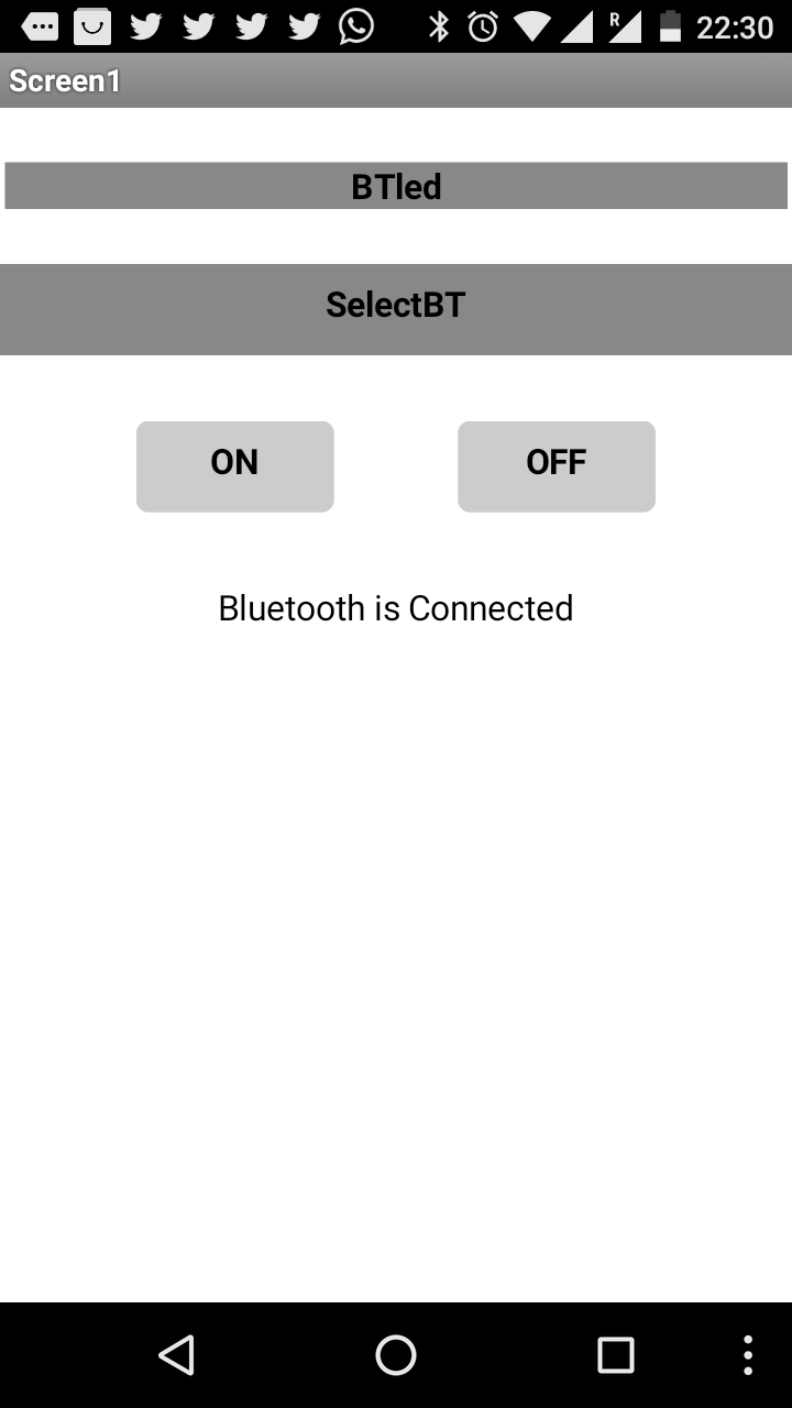
Following video depicts the output, i.e controlling the LED via the Android APP.
Testing on Attiny-44
After testing the code on Arduino, now I plan to try it on the RGB board made as part of my Output devices week. And here I am trying to control it via bluetooth using an Android App. Since Attiny44 do not have a serial communication hardware, we needed to use the software serial. This is done by initiating software serial by setting two pins as the Rx and Tx pins.
Try-1 on the RGB board (Unsuccessful)
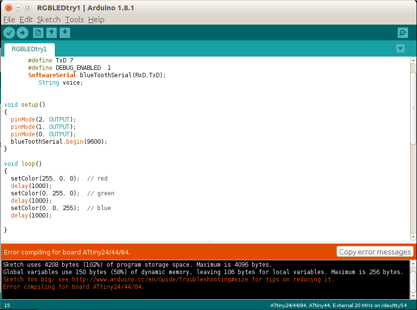
#include <SoftwareSerial.h> #include#define RxD 3 #define TxD 7 #define DEBUG_ENABLED 1 SoftwareSerial blueToothSerial(RxD,TxD); String voice; //I later found that using String will not work due to memory limitations on Attiny. void setup() { pinMode(2, OUTPUT); pinMode(1, OUTPUT); pinMode(0, OUTPUT); blueToothSerial.begin(9600); } void loop() { setColor(255, 0, 0); // red delay(1000); setColor(0, 255, 0); // green delay(1000); setColor(0, 0, 255); // blue delay(1000); } void setColor(int red, int green, int blue) { while (blueToothSerial.available()) { delay(10); char c = blueToothSerial.read(); voice += c; } if (voice.length() > 0) { blueToothSerial.println(voice); if(voice == "ON") { analogWrite(2, red); analogWrite(1, green); analogWrite(0, blue); } if(voice == "OFF") { analogWrite(2, 0); analogWrite(1, 0); analogWrite(0, 0); } voice=""; } }
Initially I tried the same logic using the string as I have done on the Arduino, but I was not able to upload that code to the attiny, as there is not enough memory available on the attiny. The error which I got is shown in the following image.
Try-2 on the RGB board - Optimizing the memory
I figured out that one way to reduce the size is to remove the vairables, and later also change the string to a one byte number. Some good reference on the memory usage could be found on playground.arduino and learn.adafruit. From page-19 of the playground.arduino and learn.adafruit.document, multiple steps are detailed for optimised memory usage.
The refined code I have used on the RGB board is mentioned below.
#include <SoftwareSerial.h>
#define RxD 3
#define TxD 7
#define DEBUG_ENABLED  1
SoftwareSerial blueToothSerial(RxD,TxD);
int state = 0; //Please note the change here.


void setup()
{
  pinMode(2, OUTPUT);
  pinMode(1, OUTPUT);
  pinMode(0, OUTPUT);
  blueToothSerial.begin(9600);
}

void loop()
{
  setColor(255, 0, 0);  // red
  delay(10);
  setColor(0, 255, 0);  // green
  delay(10);
  setColor(0, 0, 255);  // blue
  delay(10);

}

void setColor(int red, int green, int blue)
{

///////////////////////////////////////
if(blueToothSerial.available() > 0){
        state = blueToothSerial.read();
       if(state == 1)
       {
  analogWrite(2, red);
  analogWrite(1, green);
  analogWrite(0, blue);
           blueToothSerial.write("LED ON");
        }

 else if(state ==0)
  {
  analogWrite(2, 0);
  analogWrite(1, 0);
  analogWrite(0, 0);
  blueToothSerial.write("LED OFF");
    }

  }
}
The App also needed to be updated to include the single byte number instead of the text string.
Conclusion
This week I have learned and explored the basics of Interfaces and programming. I have also successfully did a Android App and connected it to my RGB LED board and via bluetooth.
The files (codes, APKs etc) created this week is available here.