Week 10
Output Devices
Objectives
Learning Outcomes
Have I ...
Documentation
I chose LED RGB to works.
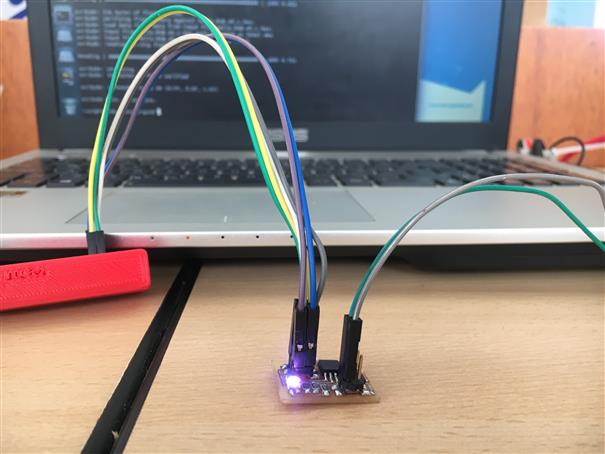
Output boards
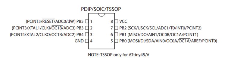
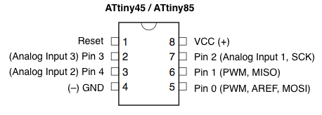
LED RGB board use Attiny45, let to checkdata sheet to understand how it works, operations and connections.
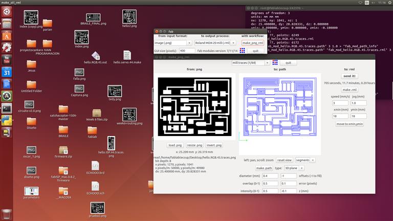
Using Modela MDX-20 lets to mill our boards. There are screenshots of parameters used. Its recommendable set speed (mm/s) at 3 or 2, but not 4 because milling tool wears very fast.
PROGRAMMING LED RGB USING NEIL'S CODE
Once your board were welded, let to programm this board. You need to download make file, and .c file.
Now, open terminal, enter to file where those were downloaded. Type the line code below, and press enter.
sudo make -f hello.temp.45.make program-usbtiny
avrdude -p t45 -c usbtiny -U flash:w:hello.temp.45.c.hex
PROGRAMMING LED RGB USING MY CODE
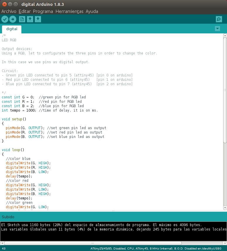
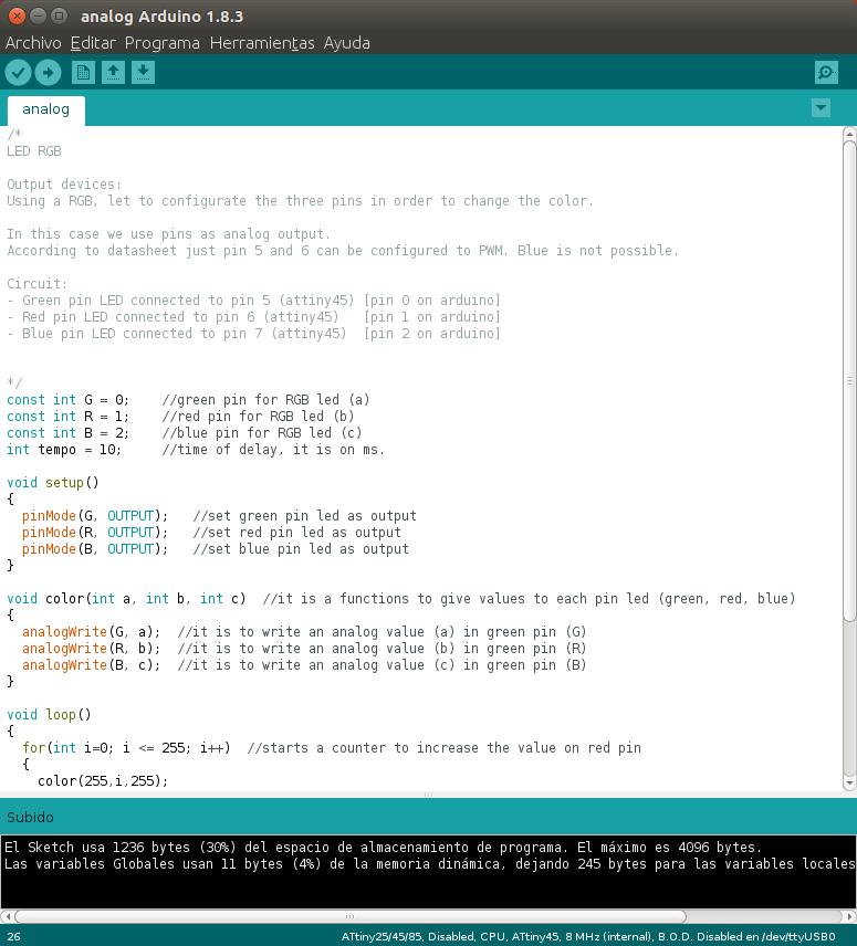
I did two kind of code. First, using pins as digital output. Second, using pins as analog output.
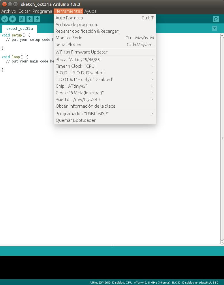
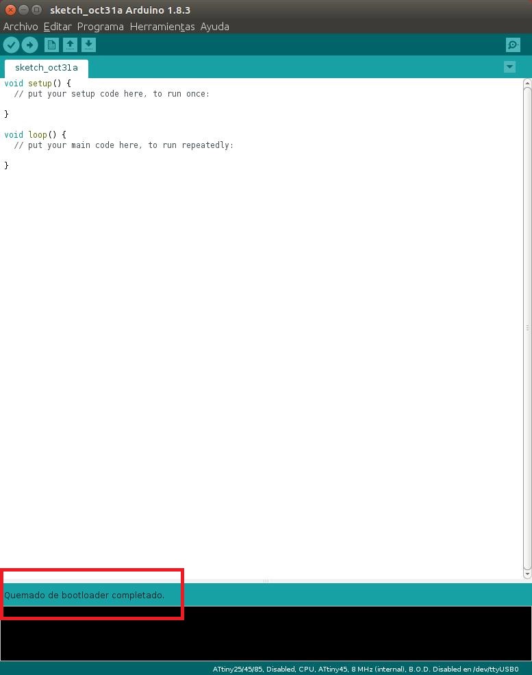
Let to burn bootloader, select options like first picture and then click on "Quemar bootloader". As result we obtain "Quemado de bootloader comlpetado"
Open "digital.ino" or "analog.ino" file (downlaod at the bottom). Click on "Verificar" or "Verify" icon (check shape). Then, click on "Subir" or "Upload" icon (arrow shape)
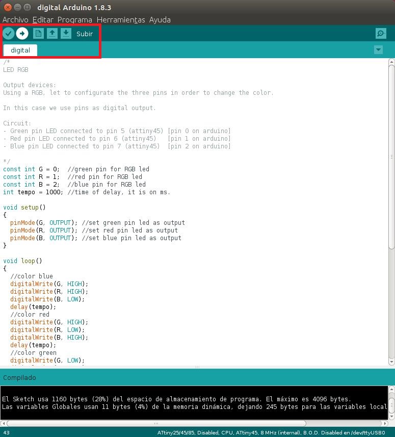
PINs as DIGITAL OUTPUT
In this case, we are using pins as digital output. Using HIGH or LOW ( 5V or 0V). As results we obtain 7 combinations, therefore 7 colors. Using one pin: red, blue, green. Two pins: magenta (red mixed blue), cyan (blue mixed green), yellow (green mixed red). Three pins: white (red, green, blue).
PINs as ANALOG OUTPUT
In this case, we are using pins as analog output, Attiny45 just have two analog pins (pin 0, pin 1), for green and red. Using values from 0 to 5 volts DC. As results we can obtain a lot of combinations. This code makes a gradient of the red and green color. When it is the turn of blue color, we can see blue light for a shor time, then it goes off.
LED RGB for my FINAL PROJECT
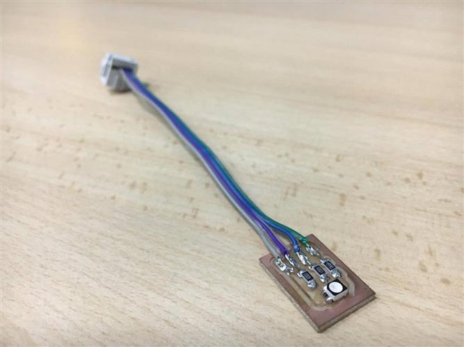
For my final project I need just Led RGB (this board doesn't have any microcontroller) to use with Jhonduino . So I design a little board, there is the led and resistors for each cathode according to data sheet. File at the bottom. Pin 4: 5Vdc // Pin 3: Red // Pin 2: Green // Pin 1: Blue

I am going to use three LED RBG boards on my final proyect.
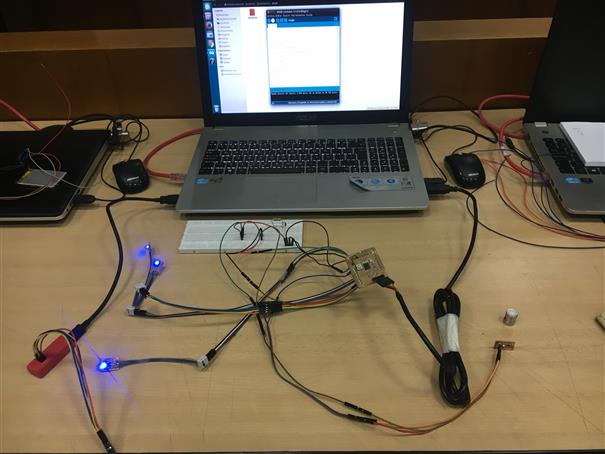
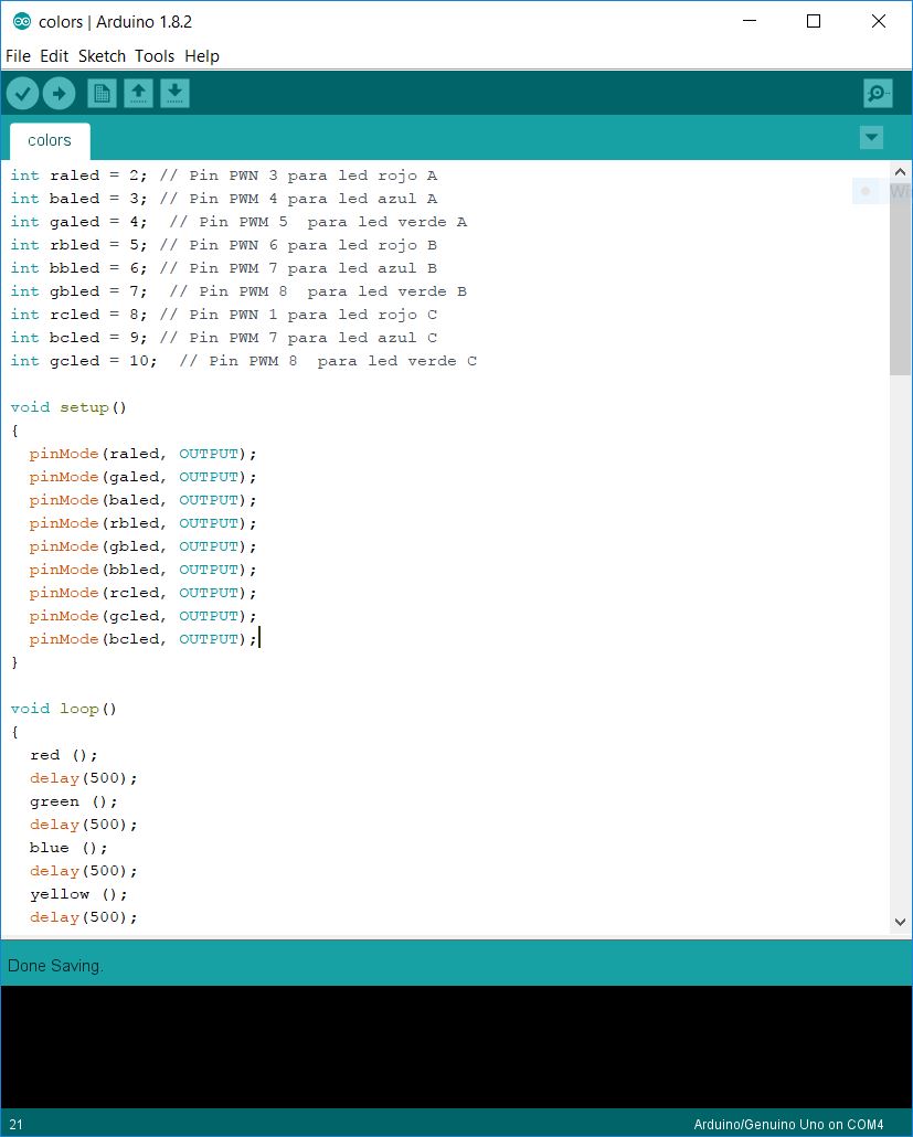
I did a code in Arduino to test mi LEDs, I used 9 digital pins, 3 per each led and using "switch case" I could have default lights.