Week 8
Embedded Programming
Objectives
Learning Outcomes
Have I ...
Documentation
During the Diploma FabAcademy the most used microcontrollers are the Attiny 44 - Attiny 45 - AtMega 328. In order to learn more, I did a quick read of your datasheets.
ATTINY 44 - Microcontroller 8-bit AVR - Has two timer and counters, 8 and 16 bit counters with two PWM channels on both - 10-bit ADC - 14-pin SOIC (We use this version) , 20-pin QFN/MLF: twelve programmable I/O lines - Operation voltage: 2.7 - 5.5 VDC - Speed grade: 0-8MHz at 2.7 - 5.5VDC || 0-16MHz at 4.5 - 5.5VDC - A low level on reset input for longer than the minimum pulse length will generate a reset, even if the clock is not running.
ATTINY 45 - Microcontroller 8-bit AVR - 8-bit Timer/Counter with prescaler and two PWM channels - 8-bit HIGH SPEED Timer/Counter with separate prescaler • 2 high frequency PWM output with separate output compare registers • programmable dead time generator - 10-bit ADC: 4 single ended channels / 2 differential ADC channel pairs - 8-pin SOIC (We use this version) , 20-pin QFN/MLF: six programmable I/O lines - Operation voltage: 2.7 - 5.5 VDC for ATtiny25/45/85 || 1.8 - 5.5 VDC for ATtiny25V/45V/85V - Speed grade: ATtiny25/45/85 > 0-10MHz at 2.7 - 5.5VDC || 0-20MHz at 4.5 - 5.5VDC - Speed grade: ATtiny25V/45V/85V > 0-4MHz at 1.8 - 5.5VDC || 0-10MHz at 2.7 - 5.5VDC - A low level on reset input for longer than the minimum pulse length will generate a reset, even if the clock is not running.
ATMEGA 328P (Used on JhonDuino) - ATMEL AVR 8-bit Microcontroller Family - 131 Powerful instructions - 32KBytes of In-System Self-Programmable flash program memory - 1KBytes EEPROM - 2KBytes Internal SRAM - Two 8-bit Timer/Counter with separate prescaler and compare mode - Two 16-bit Timer/Counter with separate prescaler, compare mode and capture mode - Real time counter with separate oscillator - Six PWM channels - 8-channel 10-bit ADC in TQFP and QFN/MLF package - 6-channel 10-bit ADC in PDIP package - Two master/slave SPI serial interface - One Programmable Serial USART - One Byte-oriented 2-wire Serial interface (Philips I2C compatible) - 23 programmable I/O lines - 28-pin PDIP, 32-lead TQFP, 28-pad QFN/MLF and 32-pad QFN/MLF - Operation voltage: 1.8 - 5.5VDC - Speed grade: 0-4MHz at 1.8 - 5.5VDC || 0-10MHz at 2.7 - 5.5VDC || 0-20MHz at 4.5 - 5.5VDC
*SOIC package(Small Outline Integrated Circuit) *QFN package(Quad Flat No-leads) also known as MLF (micro leadframe) *PDIP package(Plastic Dual In-Line) *ADC(Analog-to-Digital Conversion)Programming Jhonduino
I have had Arduino installed. It is necessary add a new board on Arduino boards. In accordance with microcontroller used, there are two configurations.
Using ATMEGA38
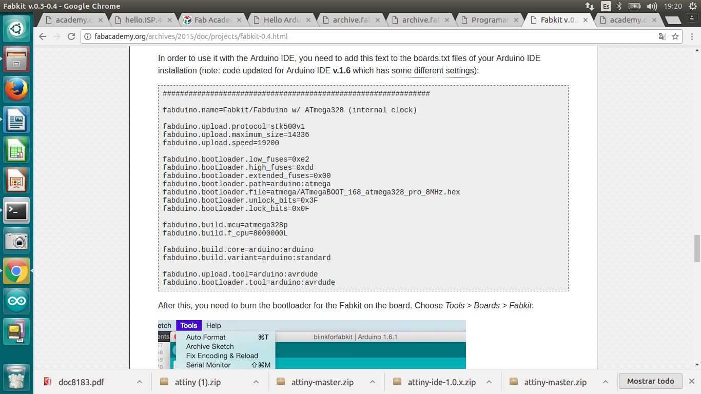
Using ATMEGA38P
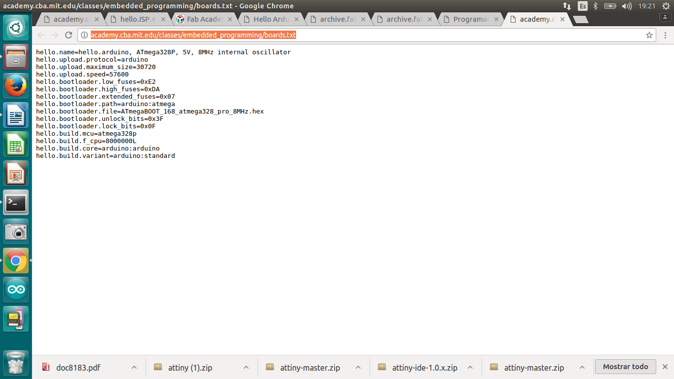
Save those code lines on .txt files and copy to arduino boards. Then, when arduino is opened you could find your board.
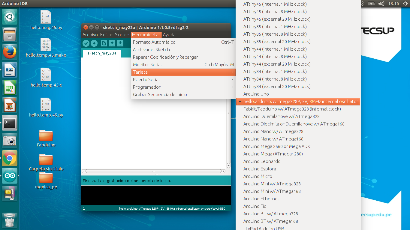
Steps to program your board:
1.Connect your FabISP and FTDI cable 2.Open Arduino IDE 3.Choose your board [on Tools] 4.Choose your serial port. /dev/ttyUSB0 in Ubuntu and COM 1 in Windows (number can change on both cases) [on Tools] 5.Choose your programmer "USBtinyISP" [on Tools] 6.Develop your code and to verify if is well written click on "Check Icon" 7.When you want to programm your board click on "Arrow Icon" and just wait 8.If there is a problem it would appear on the bottom
Programming Hello world board
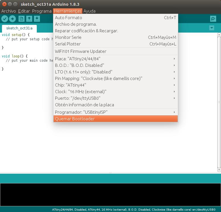
Lets to programm a Hello world board. Open Arduino software. First step is to "Burn Bootloader"
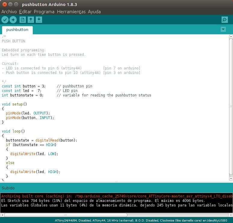
1.Click on "Tools" 2.Select: - Board: "ATtiny24/44/84" - B.O.D.:"B.O.D.Disabled" - LTO (1.6.11+only):"Disabled" - PinMapping:"Clockwise(like damellis core)" - Chip: "ATtiny44" - Clock: "16MHz(external)" - Puerto: "/dev/ttyUSB0" - Programador: "USBtinyISP"
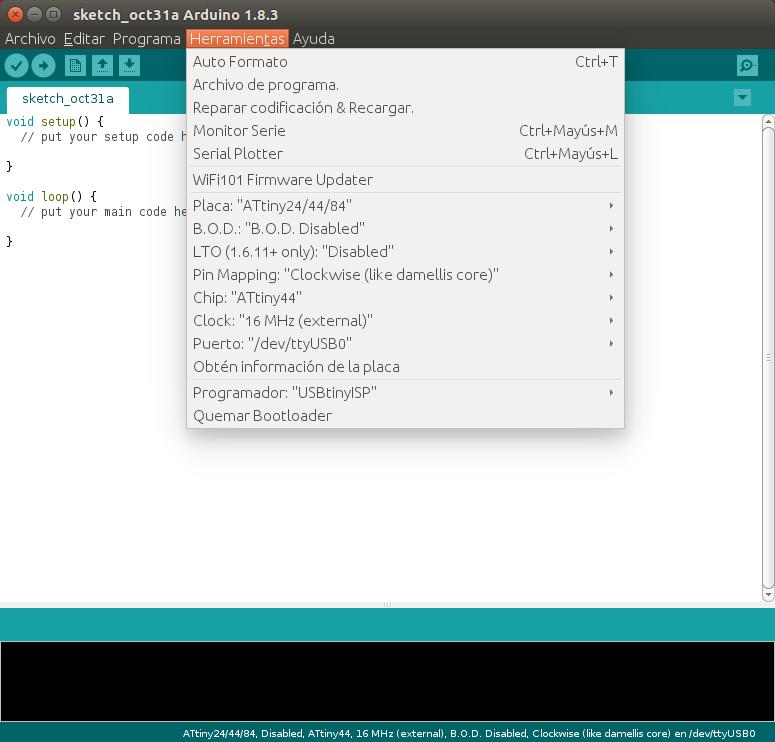
Click on "Burn Bootloader" (Quemar bootloader)
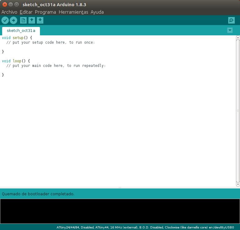
If "Burn Bootloader" was well done. This message going to appear: "Quemado de bootloader completado" ("Done")
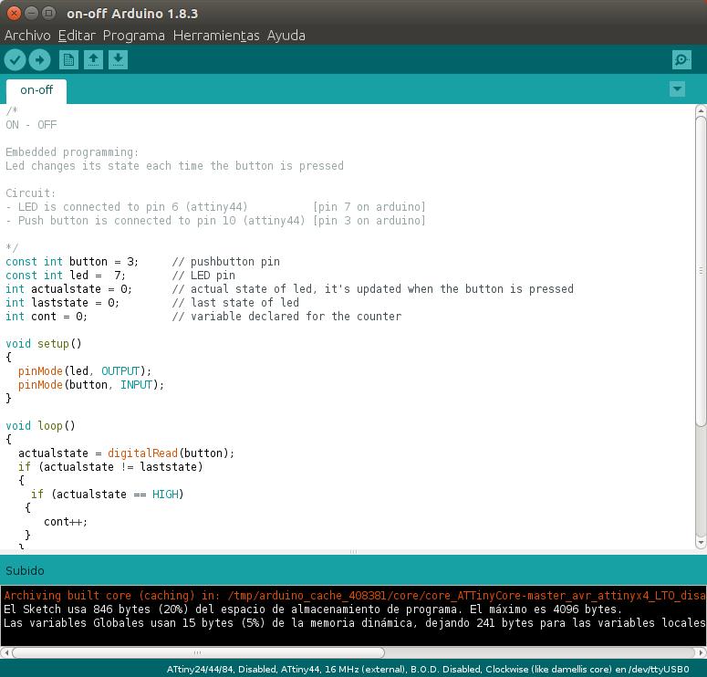
Open "on-off.ino" arduino file. Can download it at bottom. To upload any file or code, first click on "Verify" icon (check shape), it checks that the code is well written. Then, click on "Upload" icon (arrow shape).
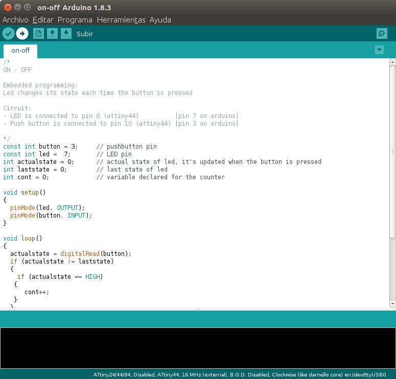
ON-OFF ARDUINO FILE
This programming each time that push button is pressend changes the let status, turns on or turn off. (file at the bottom)
PUSHBUTTON ARDUINO FILE
This programming turns on the led when the button is pressed. (file at the bottom)
Files