The activity for this week is to do something great. Using a numerical control machine. The steps for performing these tasks were as follows.:
1. Design the model in Autocad.
2. Generate code machine in Rhinoceros.
3. Prepare the machine.
4. Execution of work.
5. Mechanical Assembly.
6. Tests in real situation.
Watch the following video of the construction process from design to execution.:
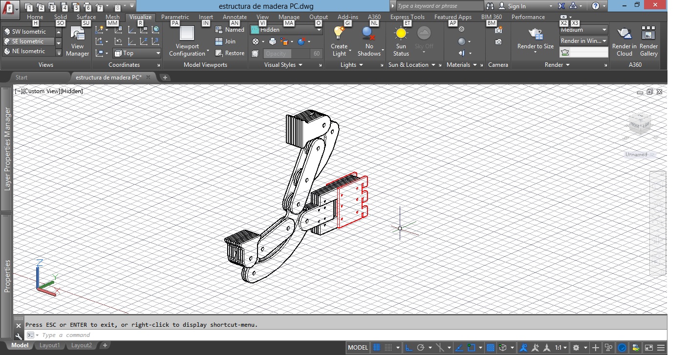
STEP 1: DESIGN MODEL IN AUTOCAD
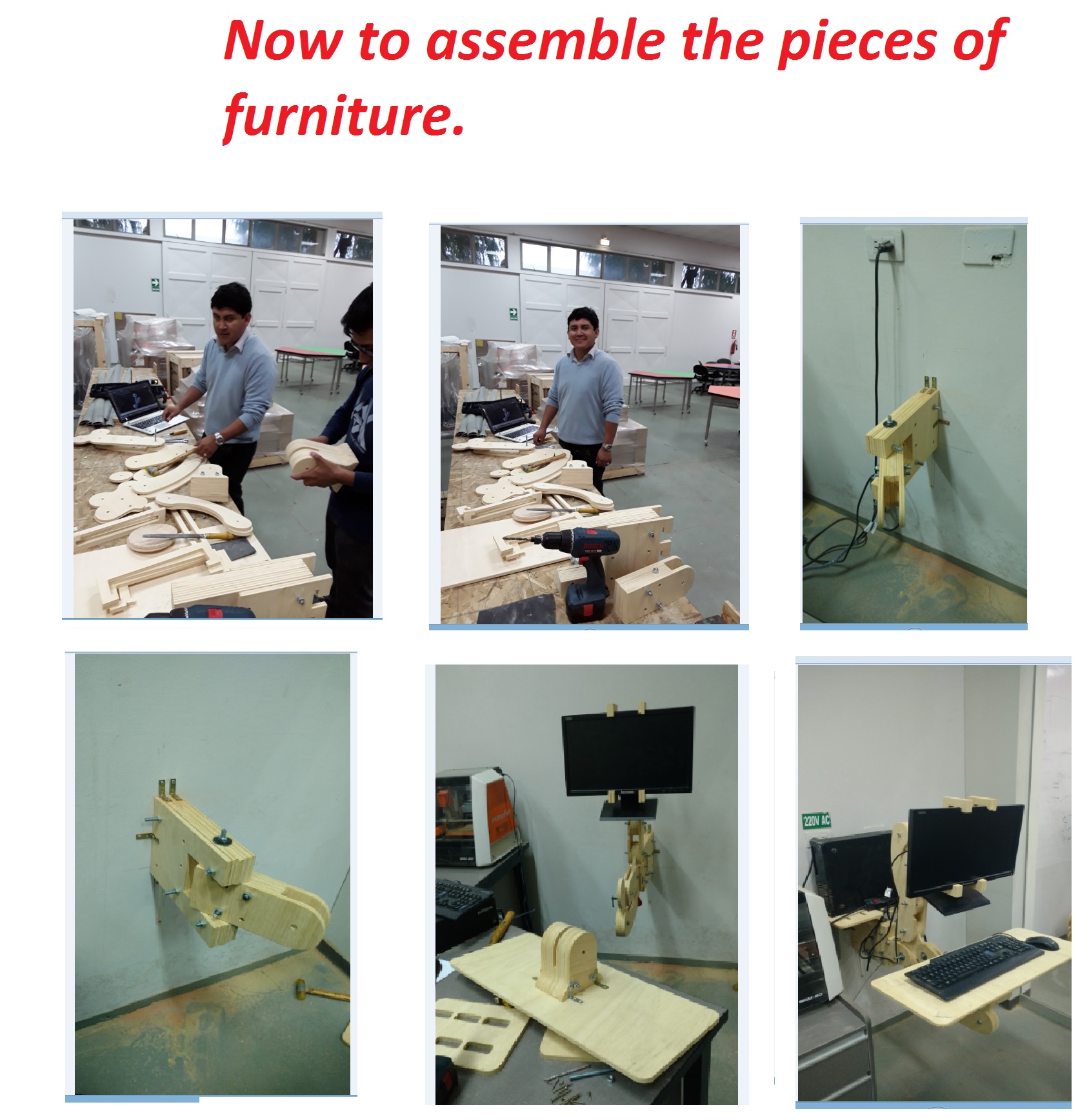
For this activity I decided to design a piece of furniture for the CNC machine, which is installed on the wall. I used Autocad and Rhinoceros to develop the design. Now this design allows me to clean the PC more comfortably.
It was observed that the machine has a tolerance of 0.2mm. Tolerance varies by the type of milling cutter used. For example if I cut a piece that has a hole of 3mm and the milling cutter is 6mm in diameter this work will be impossible for the machine.
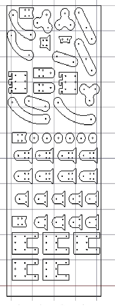
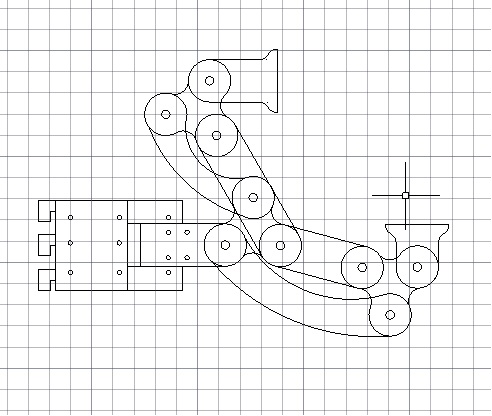
The parts and the assembly process are shown in the following image:
Finally the design in autocad was exported to DXF format
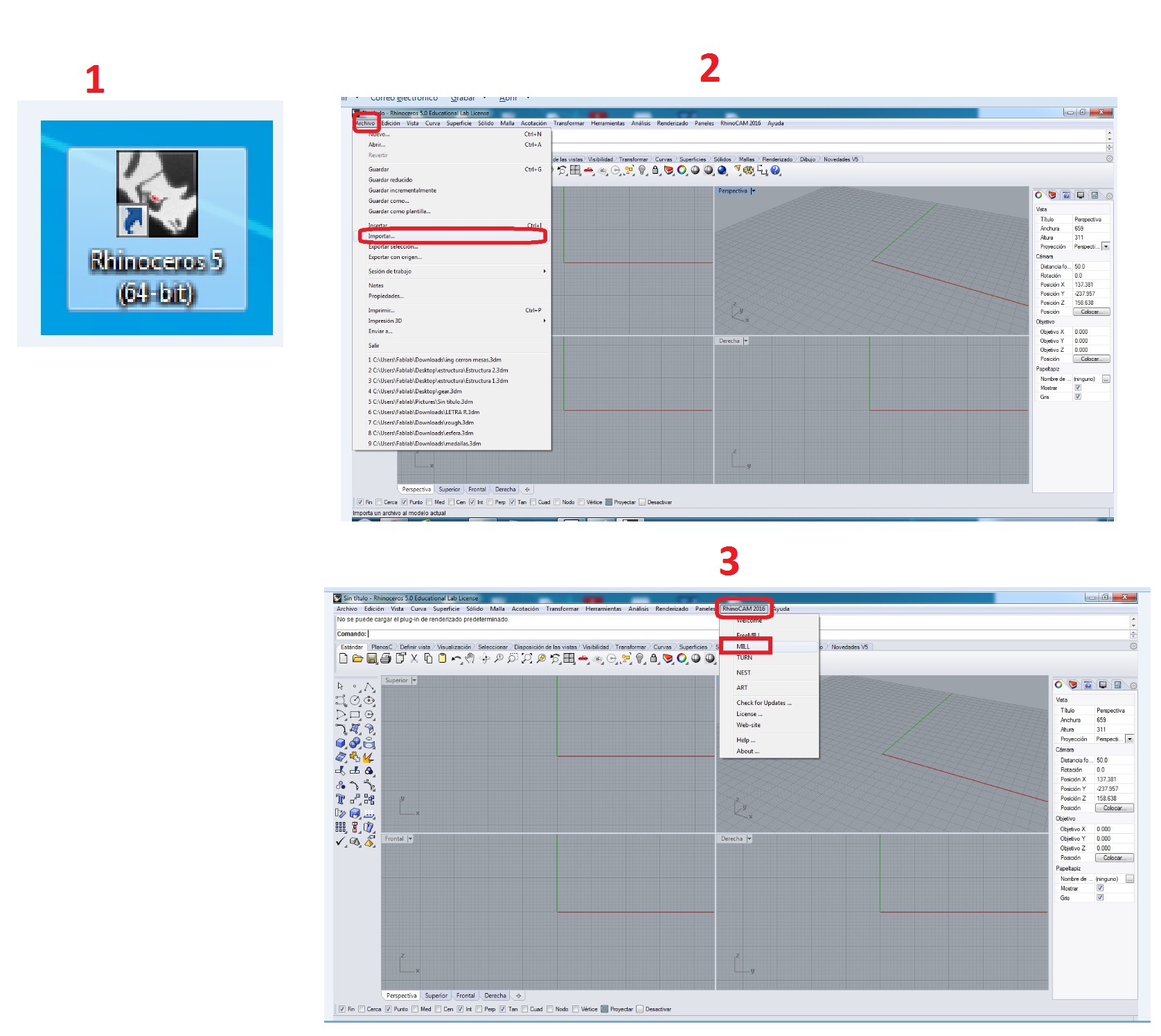
STEP 2: GENERATION CODE MACHINE IN RHINOCEROS
Software Used for to generate code machine is rhinoceros, and are as follows:
1.- Open Rhinoceros5.
2.- Import files DXF format.
3.- Click RHINOCAM and then clic a MILL.
4.- A window will appear"RhinoCam 2016 Machining Browser"
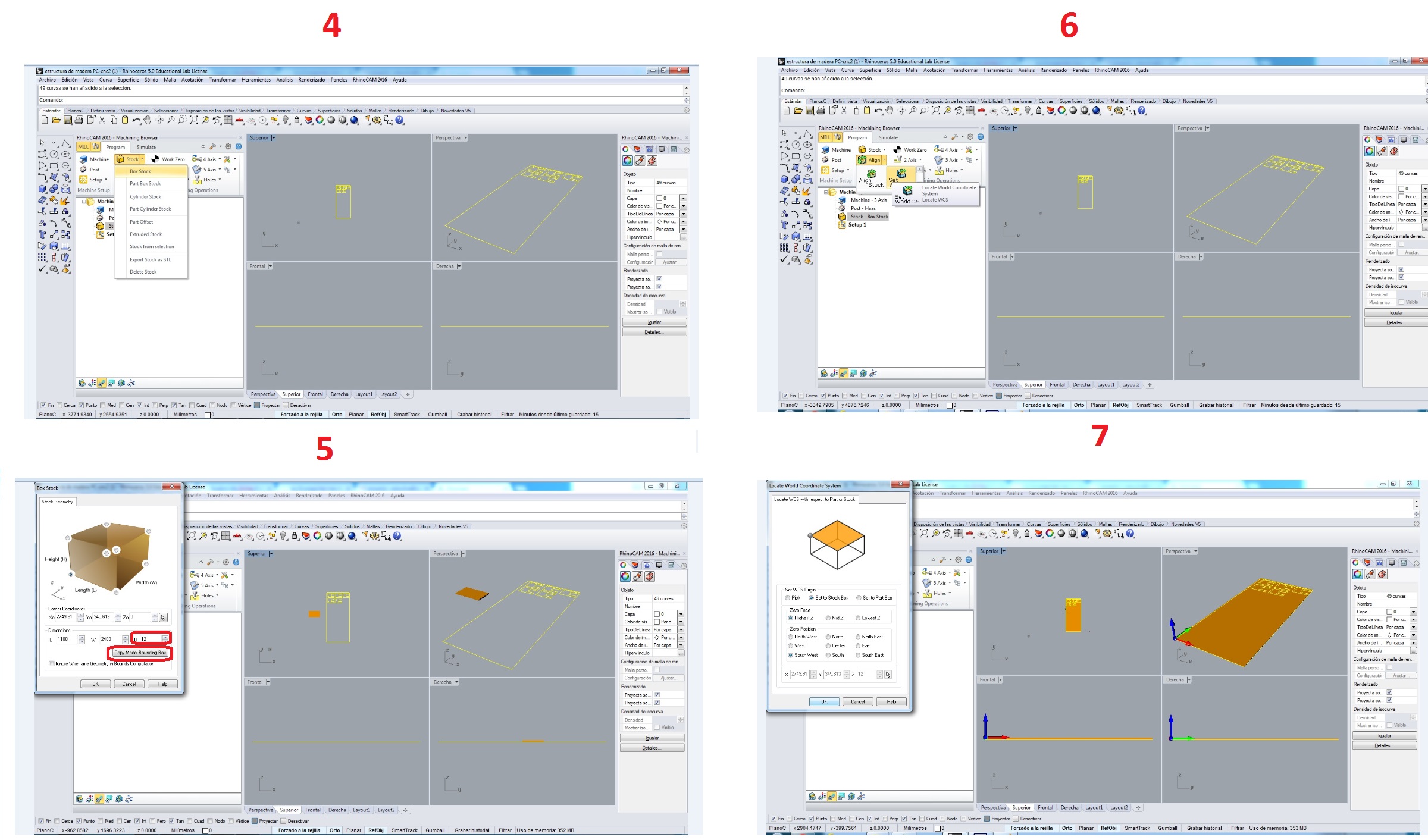
5.- Choose Stock / Boxstock as show in figure 4.
6.- The window will appear as show in Figure 5 and configure "Copy Model Bounding Box" then write the height of the wood in this case 12mm.
7.- Choose Align / Set World C.S as show in figure 6.
The window will appear as show in Figure 7 and configure SET WCS ORIGEN: set to stock box; ZERO FACE: Highest Z; ZERO POSITION: South West; and then click OK.
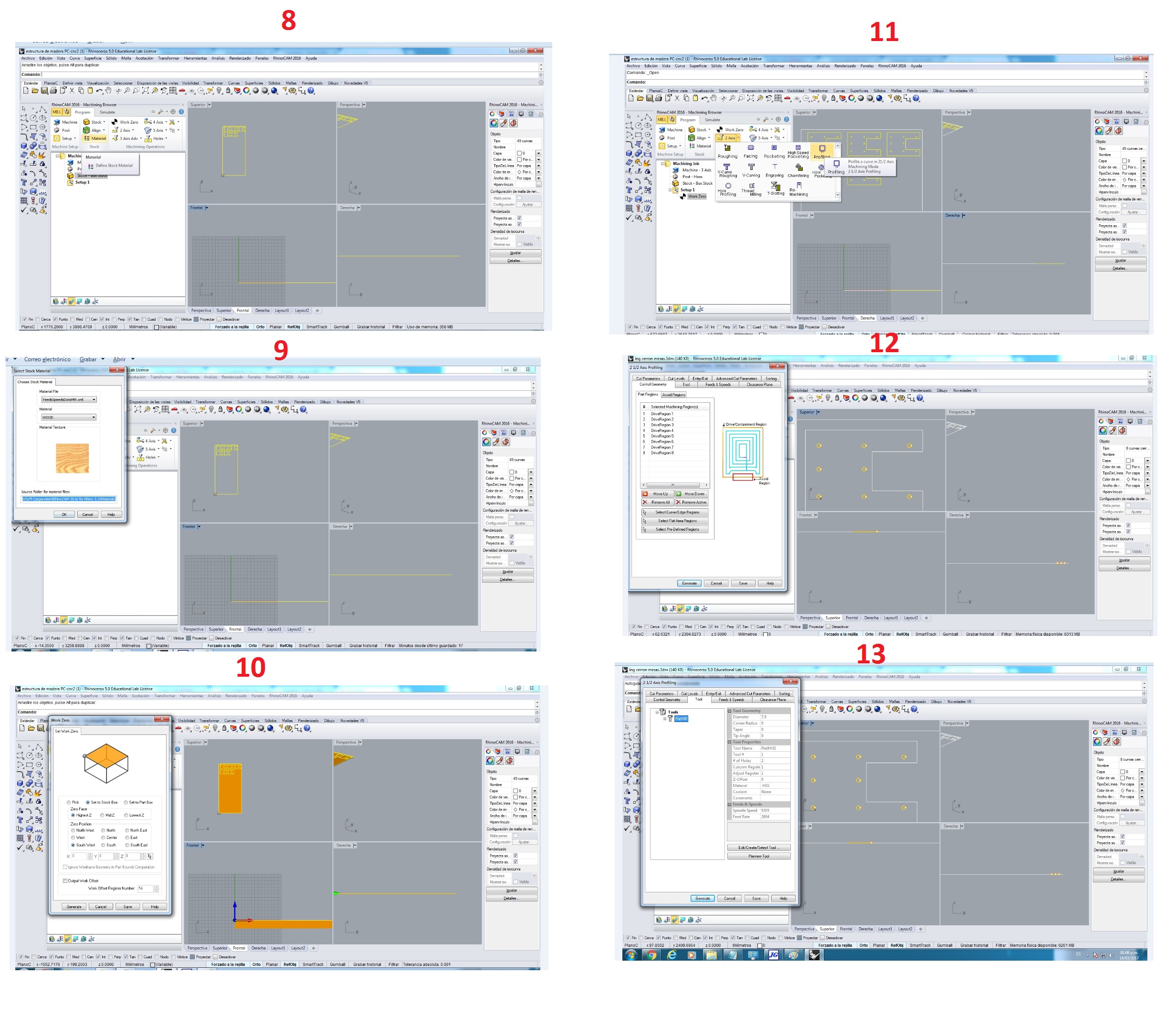
8.-Choose Material as show in figure 8.
9.- Choose Wood as Show in figure 9.
10.-Choose Work to Zero as show in figure 10 and configure WORK TO ZERO: Set to Stock Box; ZERO FACE: South West. And then click GENERATE.
11.- Choose 2 Axis / Profiling as show in figure 11.
12.- The window will appear as show in figure 12 and configure click to SELECT CURVE / EDGE REGIONS and select the shapes to cut and then ENTER.
13.-Choose Tool / FlatMill as show in figure 13.
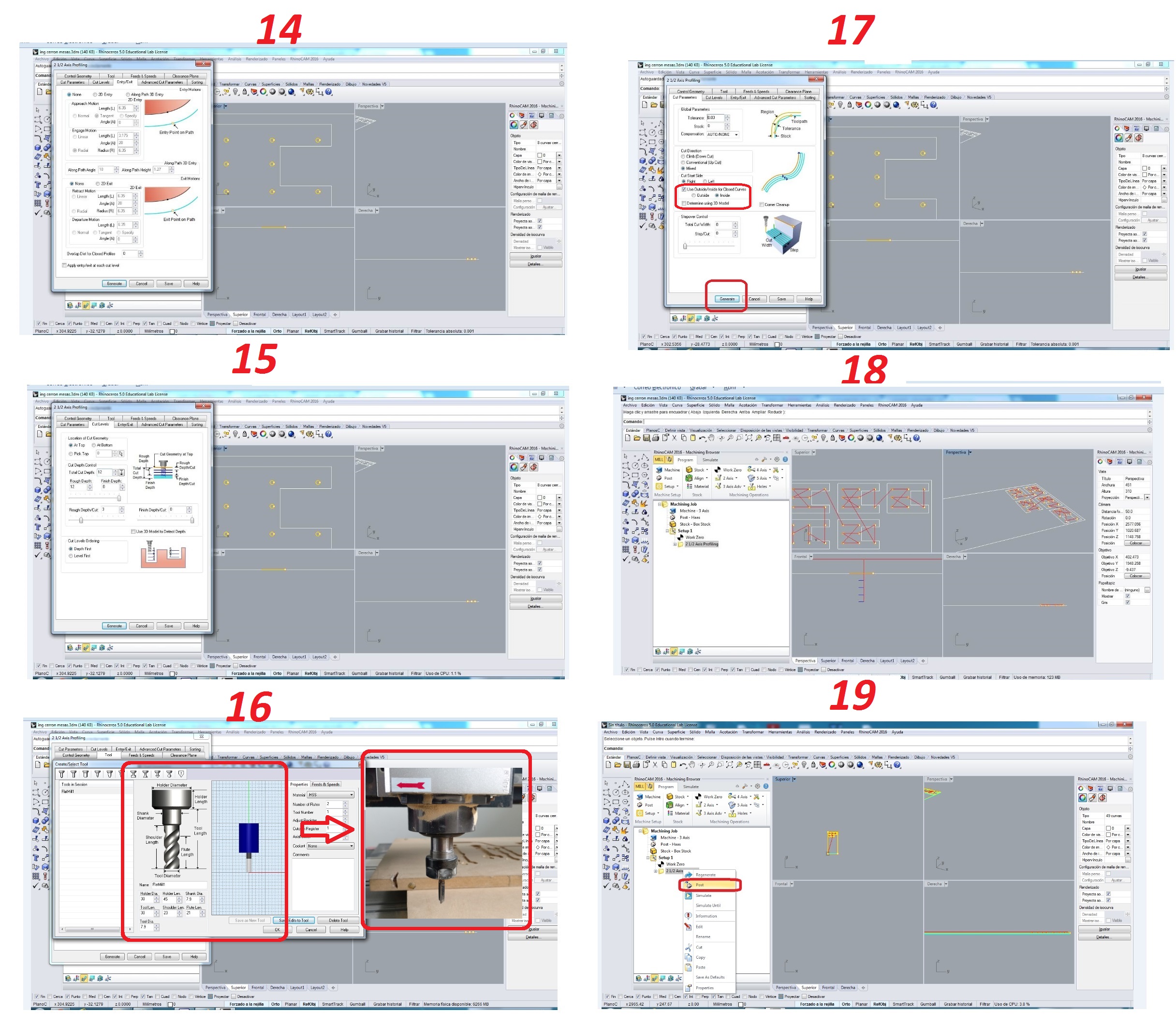
14.- Choose Entry / Exit and configue as show in figure 14.
15.- Choose Cut Levels and configure as show in figure 15. LOCAL OF CUT GEOMETRY: At Top; CUT DEPTH CONTROL: Total Cut Depth 12mm and Rough depth/cut 3mm.
16.- Choose Tool / FlatMill and configure as show in figure 13 and 16. These data are obtained of the machine.
17.- Choose Cut Parameters and configure as show in figure 17. Click to enable inside or outside. And then click GENERATE.
18 and 19.- Now click right in "2 1/2 Axis Profiling" as show in figure 18 and 19. Click Post.
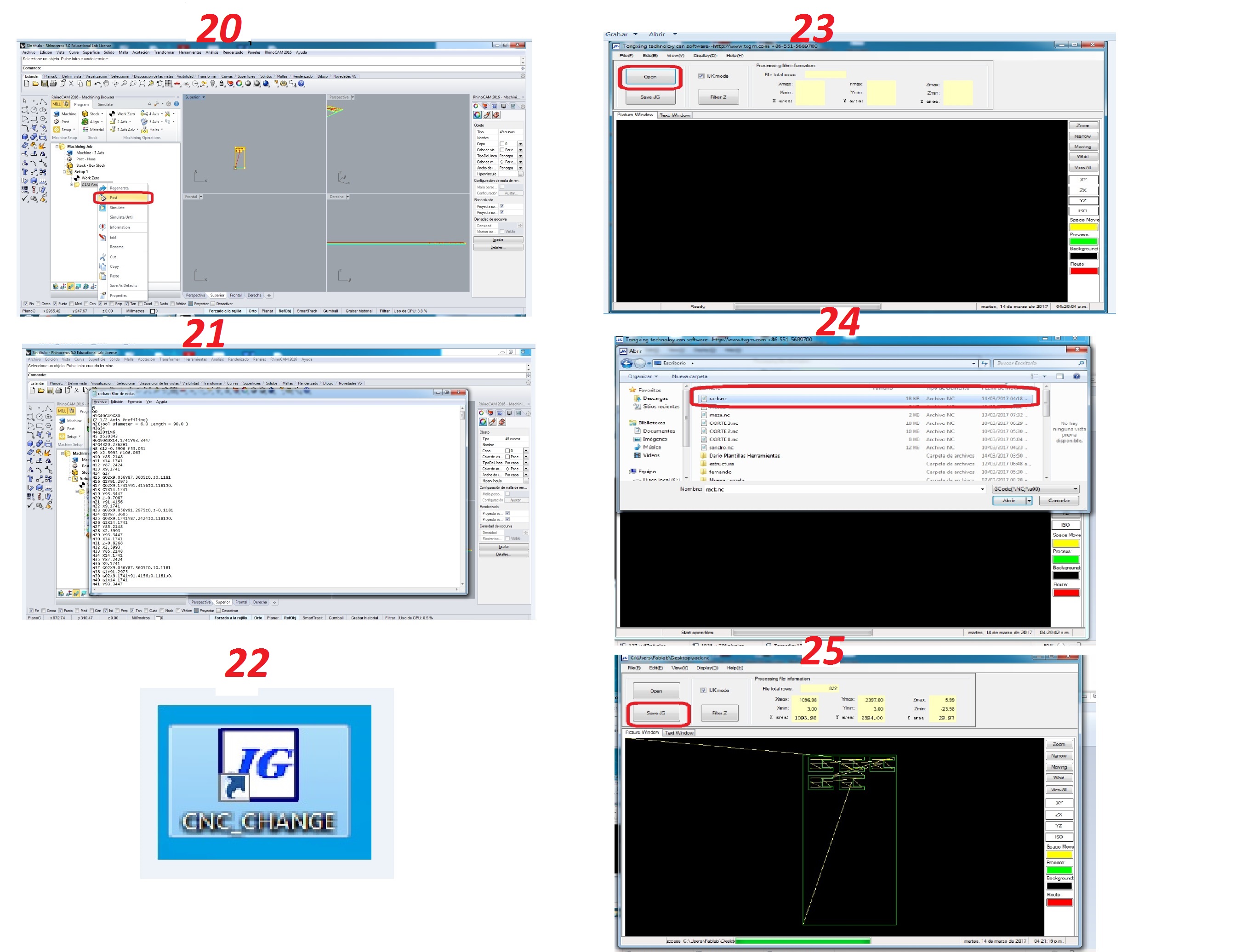
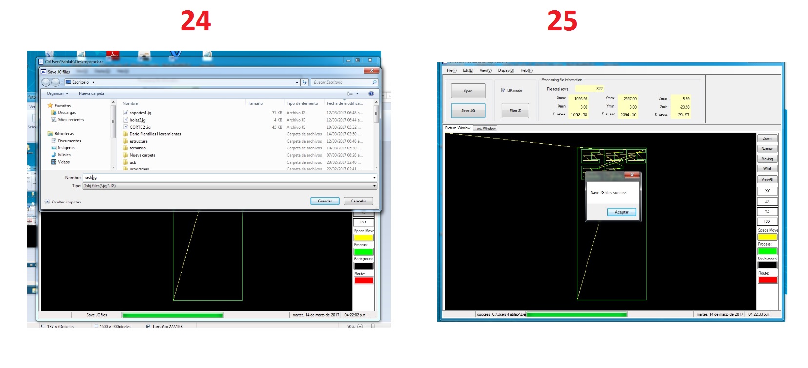
20 and 21.- Then the windows will appear to save file in format NC and save as show in figure 20 and 21.
22.- Open CNC CHANGE as show in figure 22
23 and 24.- Open File in format NC as show in figure 23 and 24.
25.- Then to save the file converted in format JG.
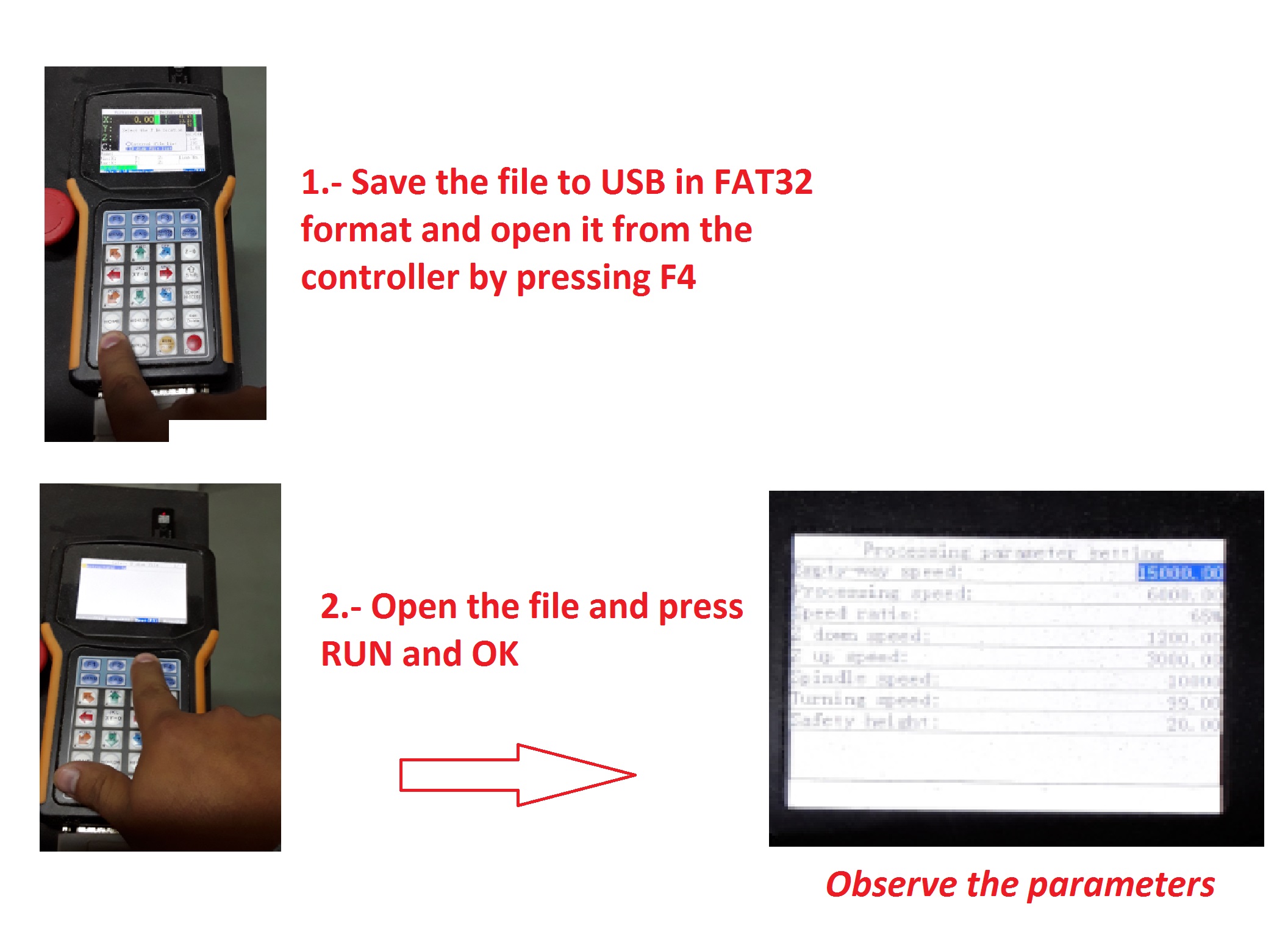
Once done this file save in a USB with format FAT32.
STEP 3: PREPARE THE MACHINE
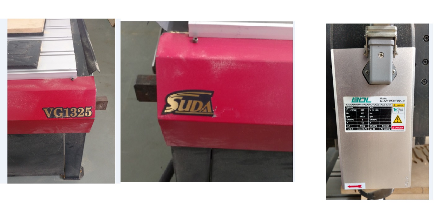
Technical data of machine:
Maker: SUDA
Model: VG1325
Motor: 220 Vac ~3; 300 Hz; 18000RPM; 3kW; 12A; FP: 0.75.
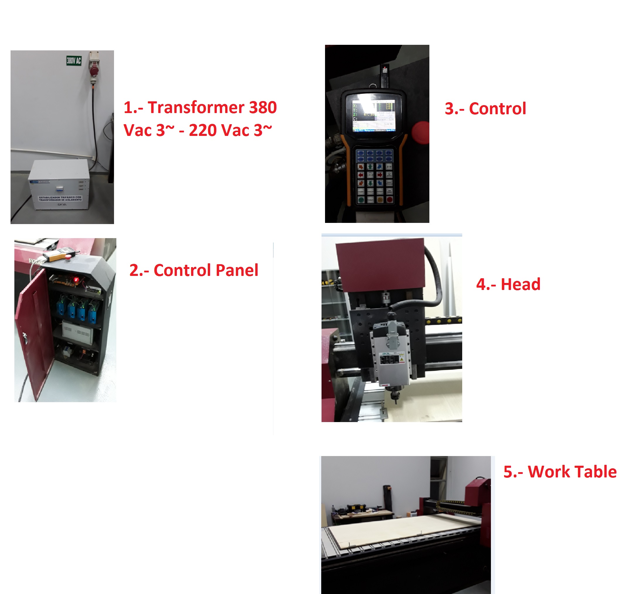
These parts are:
1.- 01 Transformer 380Vac 3~ - 220Vac 3~ Power: 6kVa
2.- 01 Control Panel contains: 01 Control Card, 04 Driver axis X-Y-Z, 01 Speed Control.
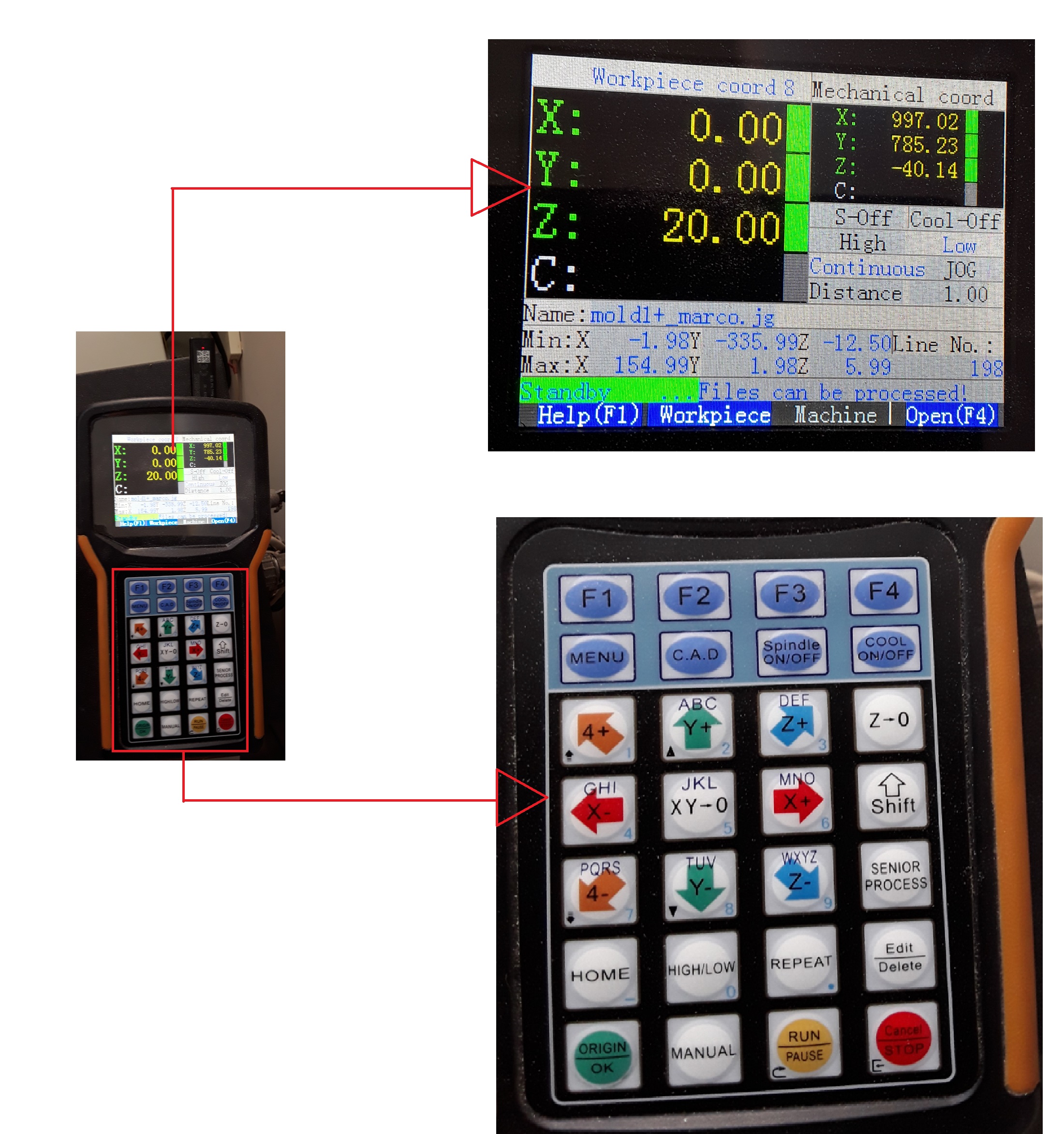
3.- 01 Control with USB, there is the operation of the machine.
4.- 01 Head contains: 01 motor, 01 Collect Chuck 6mm and 01 milling cut.
5.- 01 Work Table contains: 06 Fasteners, 10 sacrificial plate.
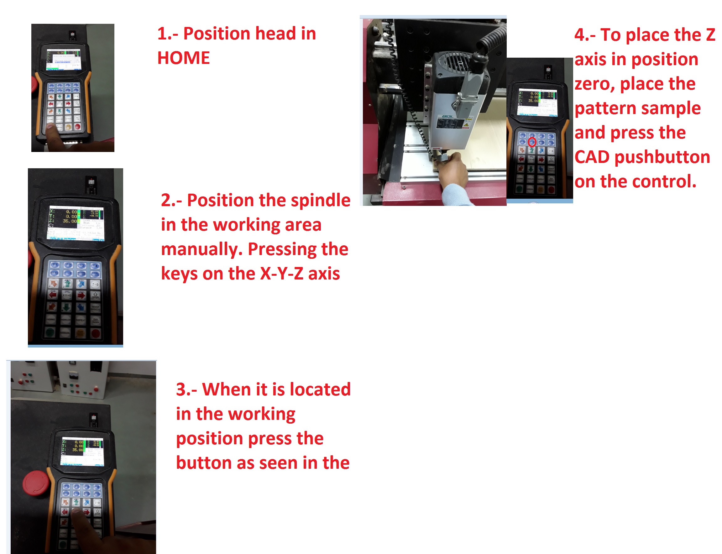
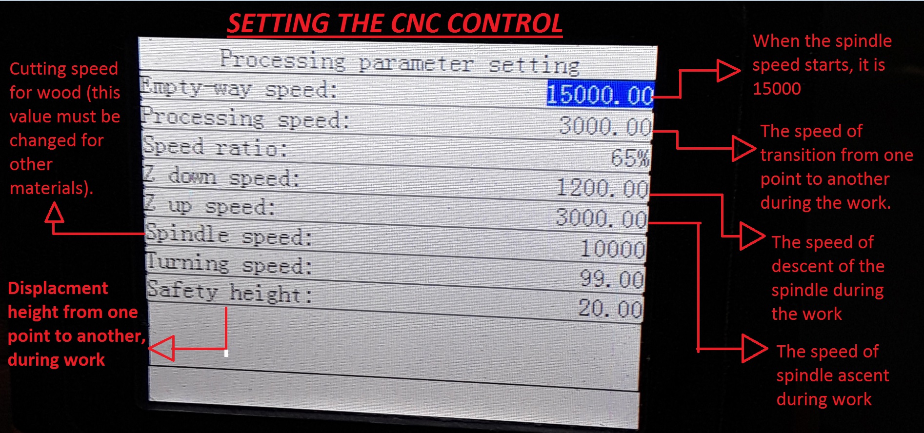
Preparation procedure machine:
STEP 4: EXECUTION OF WORK
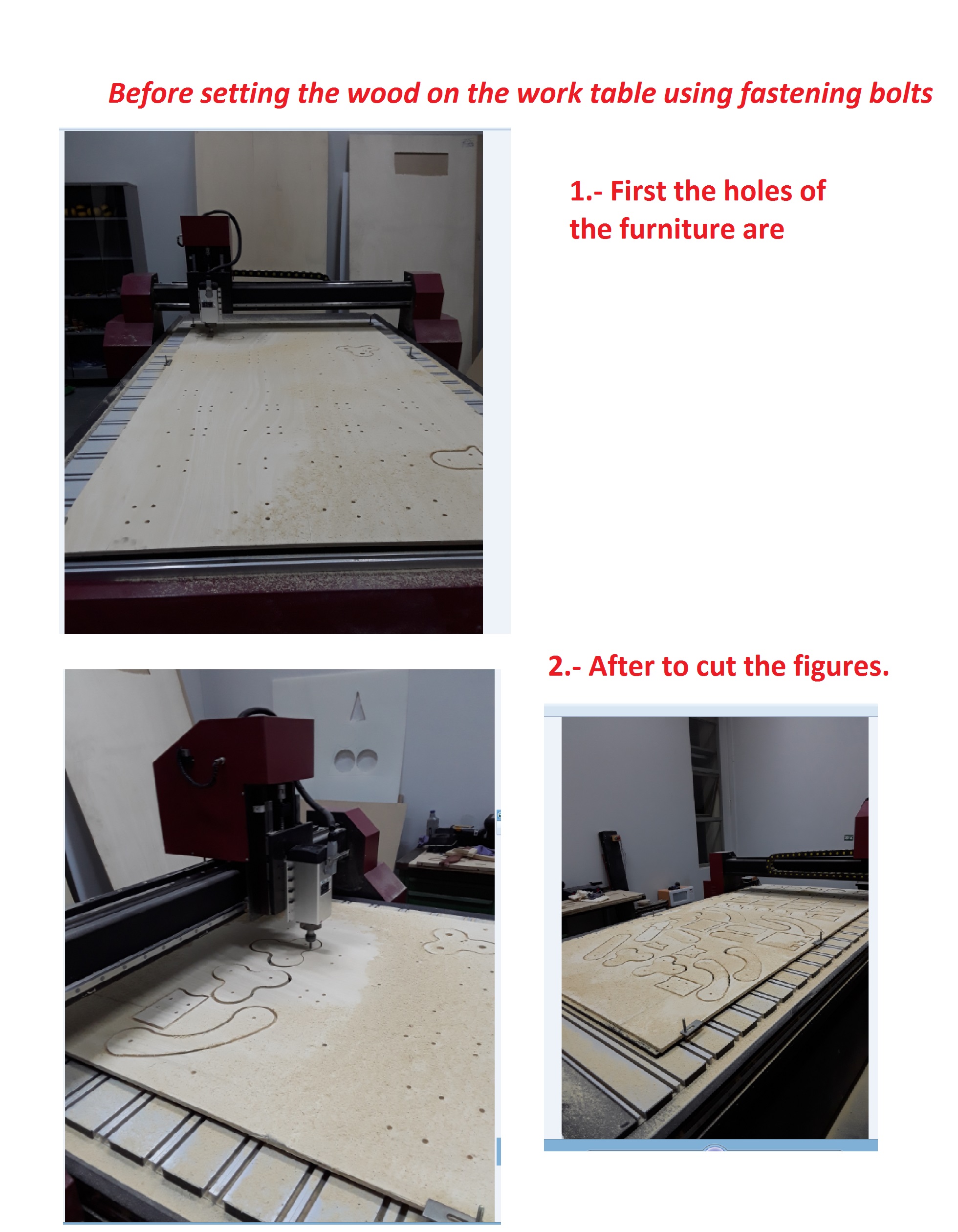
Before executing the work fix the wood on the plate of sacrifice.
Consider executing the holes first then the shapes of each piece.
STEP 5: MECHANICAL ASSEMBLE
To assemble using mounting planes and tighten with bolts and nuts.
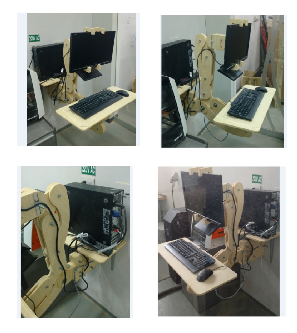
STEP 6: TEST IN REAL SITUATION
The tests of the furniture were done in the laboratory of FAB LAB TECSUP and with the computer of the wood cutter, as seen in the figure.
OBSERVATION:
1.- The selection of "outside or inside" is important to define in the rhinoceros program (see Figure 15).
2.- Can Take advantage of the spaces of the wood, configured as shown in Figure 5 and 7.
3.- The dimensions to be worked must be smaller than the diameter of the milling cut in this case of 6mm.
4.- 4 times the head travels through the figure this is configured in figure 15.
5.- The data for completing the procedure in Figure 16 are taken from the spindle that is in the head.
6.- The faster the speed of the spindle, the faster the work will be performed, ie the times the spindle performs the stroke is smaller
CONCLUSION:
1.- When you choose outside or inside, several files are generated that will have to be done separately. In my case in two times.
2.- Take advantage of the spaces helps to optimize resources.
3.- The accuracy of the jobs depends on the type of milling cutter to be used and the speed of the spindle.
4.- For precision or detailed work, thinner milling cutters are used because it has a smaller area of contact on the material.
5.- The speed of the spindle is inversely proportional to the depth of the stroke.