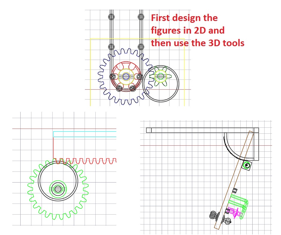
This week the project is to present design in 2D and 3D. Choose the possible design to do related to the final project.
MODEL IN AUTOCAD
The AUTOCAD program was chosen to realize the 2D and 3D design, to realize the design of the pieces and later assembly.
COMANDS AUTOCAD FOR DESIGN 2D
To perform the 3D design in autocad was used commands like: "EDIT POLYLINE" that joins the lines that form a figure. "POLAR ARRAY" that helps me generate a uniform distribution of figures on a circumference (helped me design the gears). "TRIM" is used to cut flat figures. "MIRROR" to duplicate a figure in symmetry also works on 3D. "OFFSET" to generate offsets in 2D figures used to generate thickness on the plates.

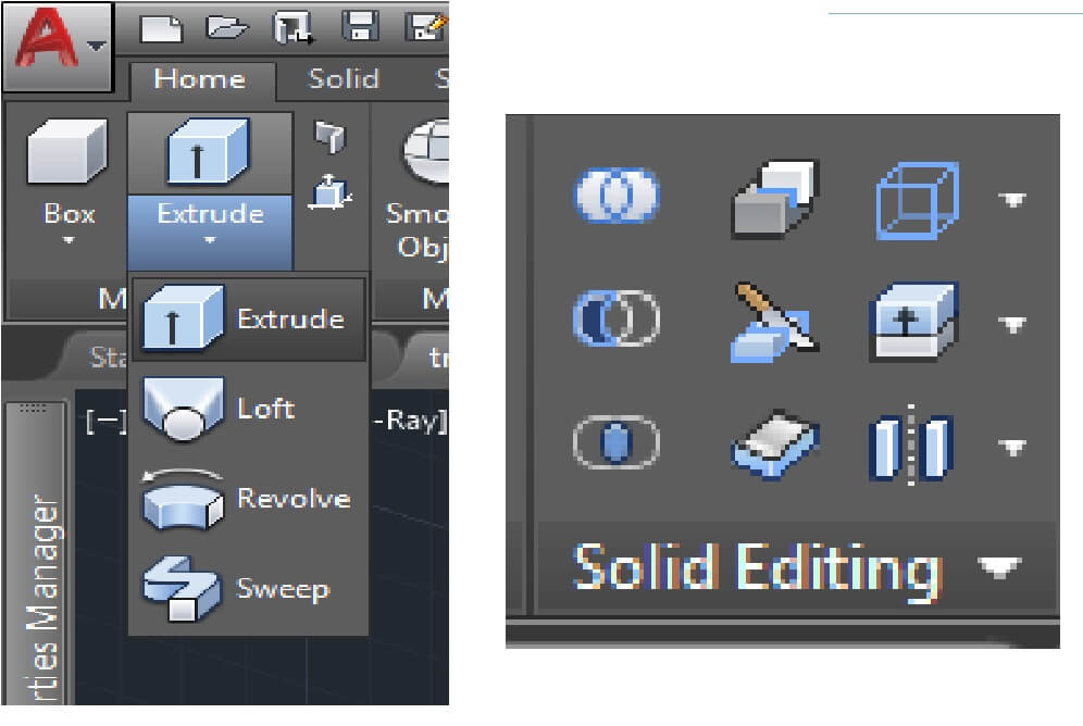
COMANDS AUTOCAD FOR DESIGN 3D
To perform 3D design in autocad the following commands were used: "EXTRUDE" to generate 3D parts from 2D figures. "REVOLVE" to generate a 3D figure from a 2D figure making it revolutionize in 360 degrees and forming a solid. "SWEEP" to generate a 3D figure from a 2D figure by following a figure (such as triangle, circumference, etc.) through a path (curve, line, spiral). "SOLID, UNION" to join several 3D pieces. "SOLID, SUBSTRACT" to subtract overlapping 3D parts. "SLICE" to cut 3D figures from a 2D reference figure. "PRESSPULL" to extend surfaces or remove surfaces in 3D figures
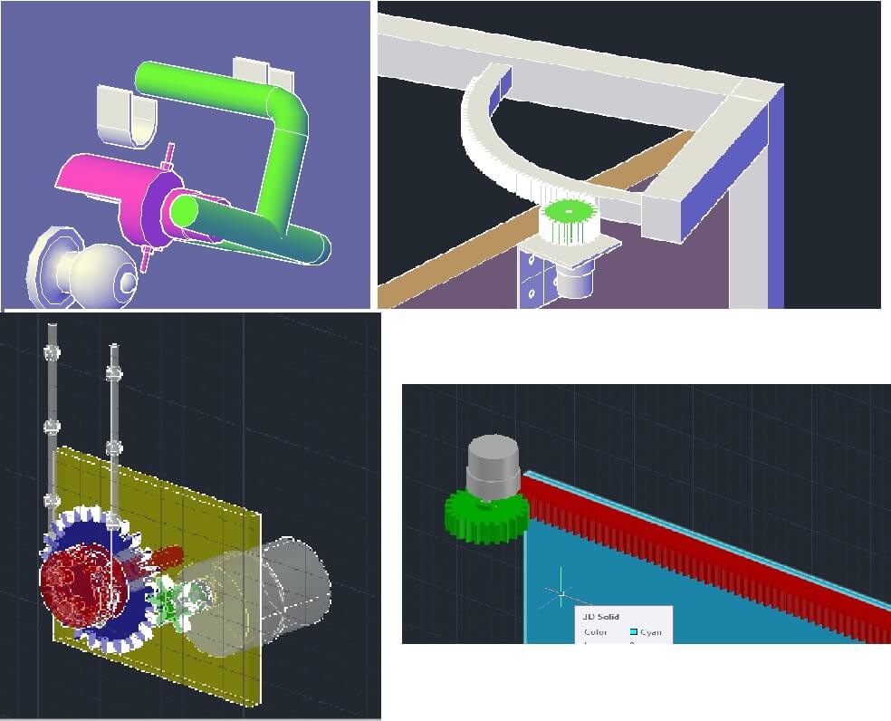
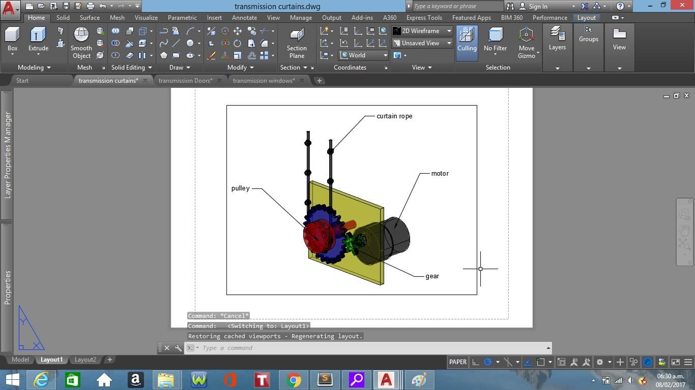
MECHANICAL SYSTEM DESIGN OF CURTAINS
Using the above commands, the transmission could be designed as shown in the figure.
The transmission consists of: an engine, 2 gears (to generate enough force and reduce speed), and a pulley for the curtain rope that will show knots each distance.
The figure shows the part of the system.
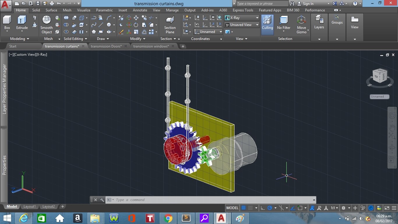
A description of the project is shown.
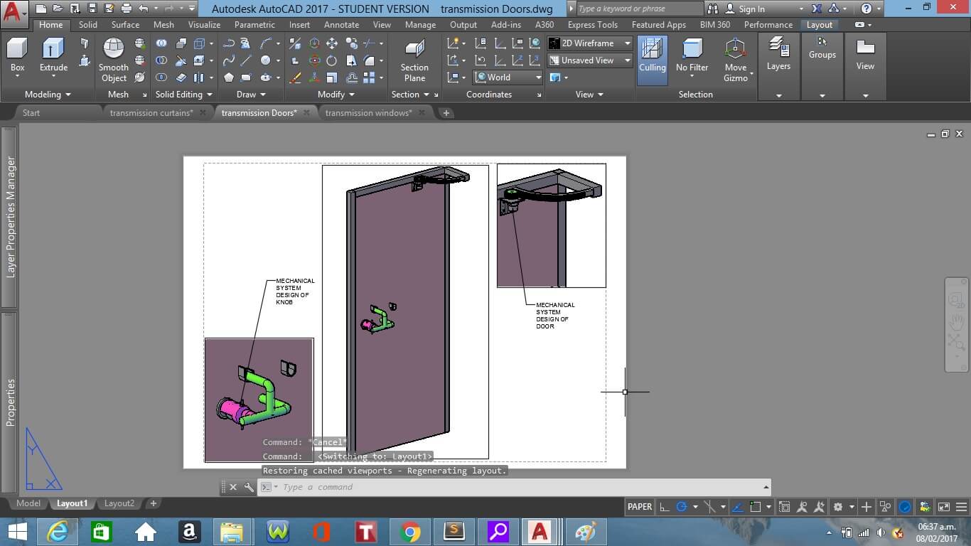
MECHANICAL SYSTEM DESIGN OF DOOR
Using the above commands, the transmission could be designed as shown in the figure.
The transmission consists of: a motor, 1 gear (to generate enough force and reduce speed), and a mechanical zip rack that will open or close the door. In addition another system was added on the door, this will turn the door knob.
The figure shows the part of the system.
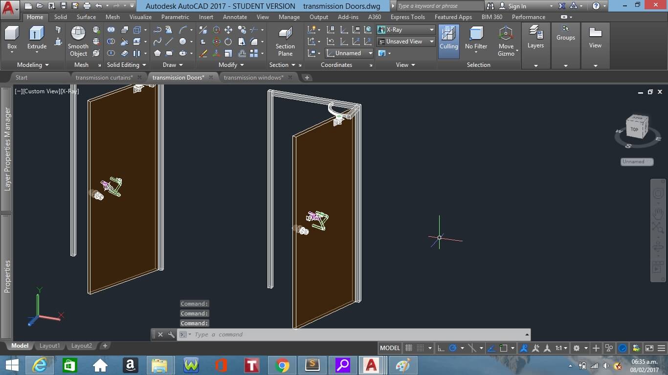
A description of the project is shown.
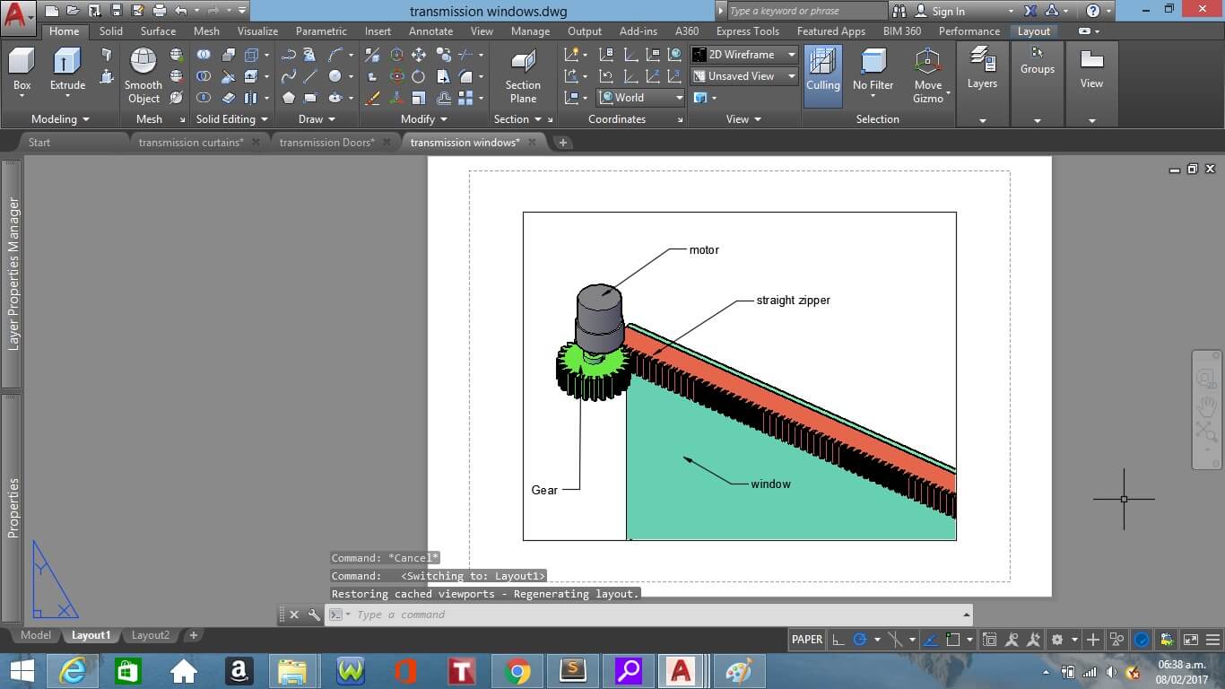
MECHANICAL SYSTEM DESIGN OF WINDOW
Using the above commands, the transmission could be designed as shown in the figure.
A straight mechanical zipper, an engine; Which will open or close the window..
The figure shows the part of the system.
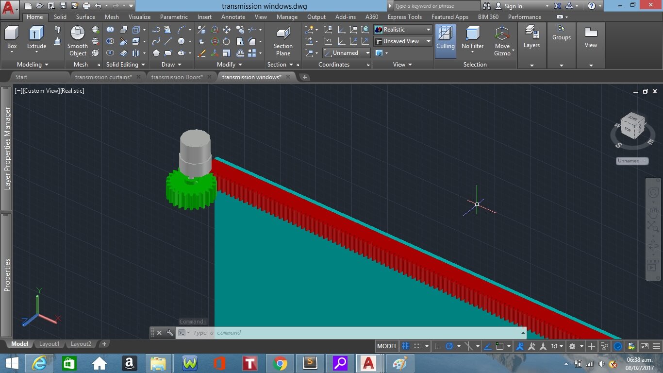
A description of the project is shown.
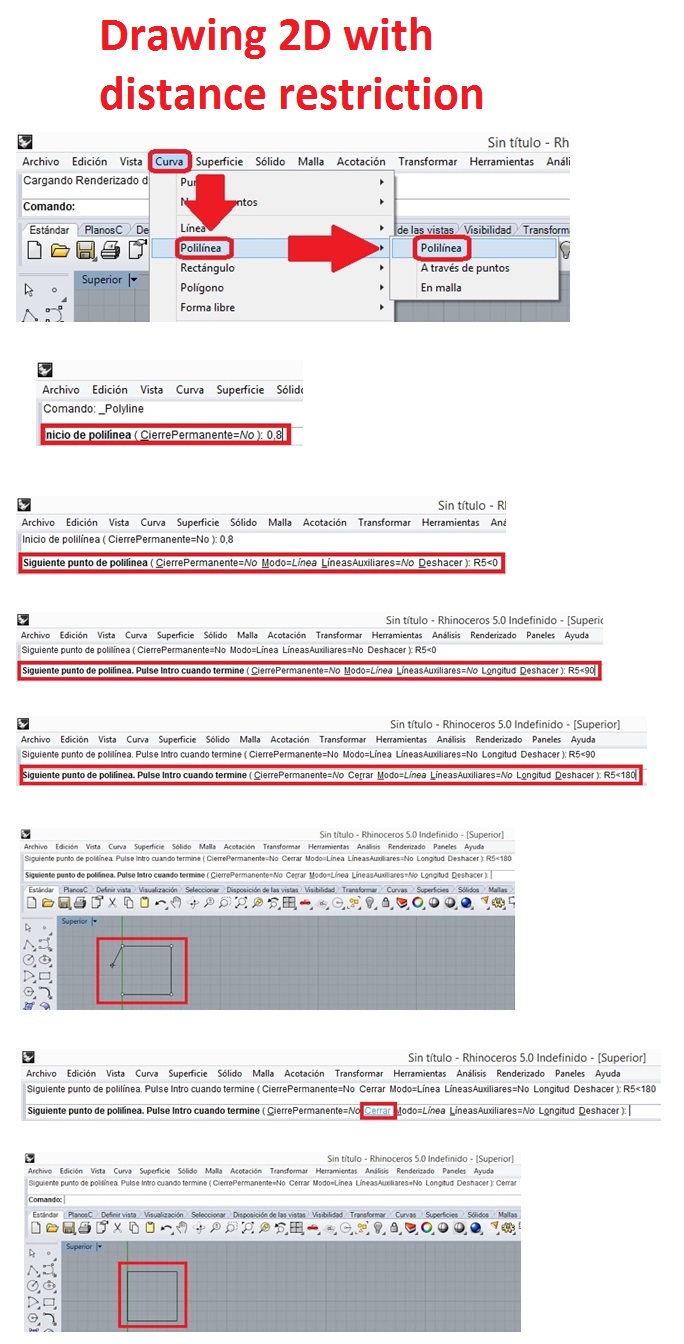
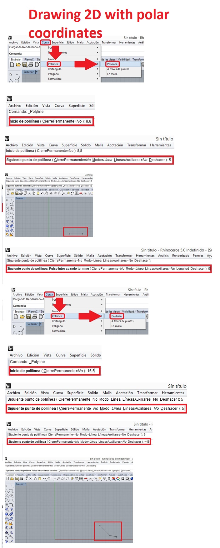
MODEL IN RHINOCEROS
The rhinoceros program is a 3D and 2D modeling platform with 4 views that accepts various formats
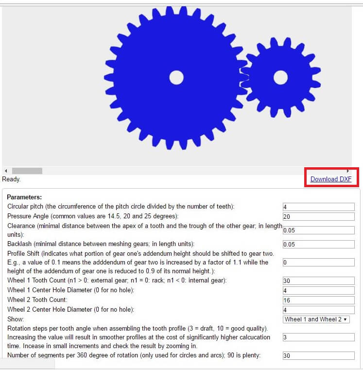
To design the gears in this program the following steps were performed
http://hessmer.org/gears/InvoluteSpurGearBuilder.html
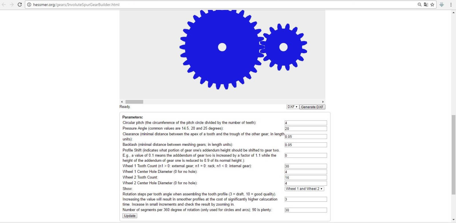
When the gear is ready for export, you need to click on "update"
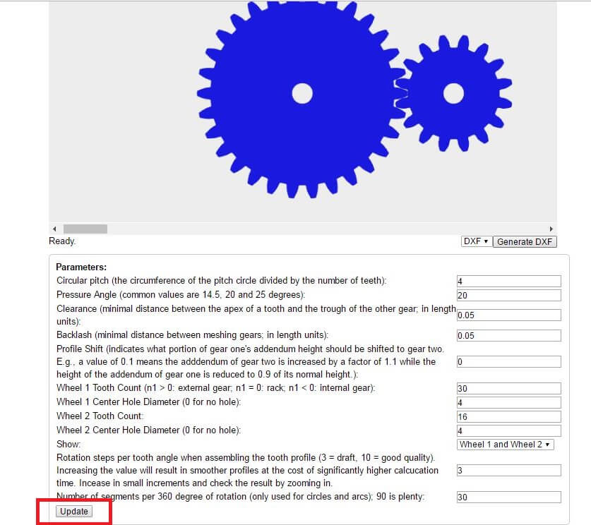
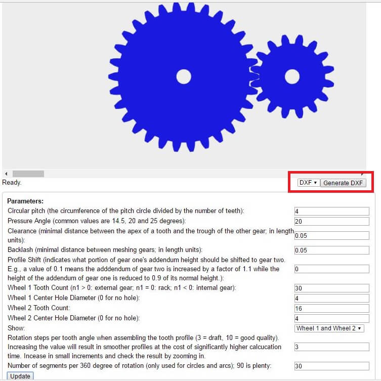
Then we click on "generate DXF"
To download the gear you must click on "generate DXF" -> "download DXF"
THEN
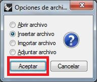
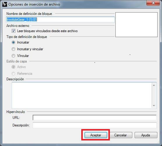
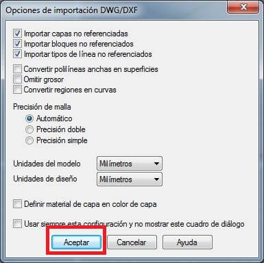
When you drag the files to rhinoceros the following windows will appear and you will accept all
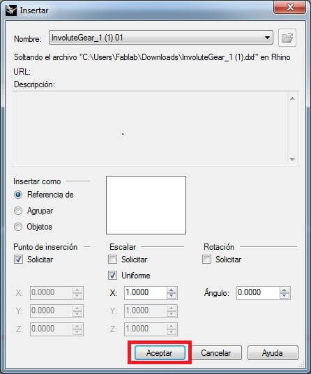
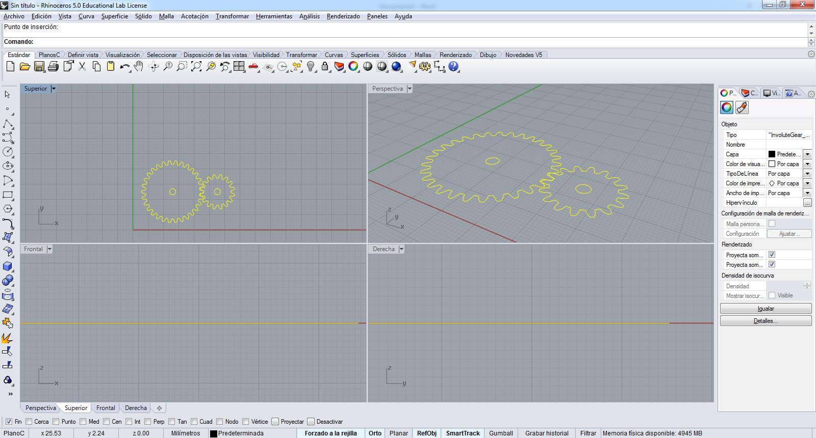
Then we will locate the file in the work area of Rhinoceros
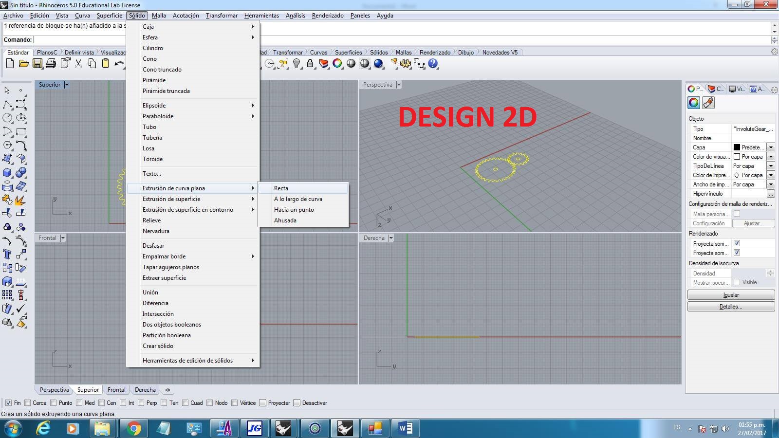
To create the solid we will extrude the surface with the tool that is observed in the following image
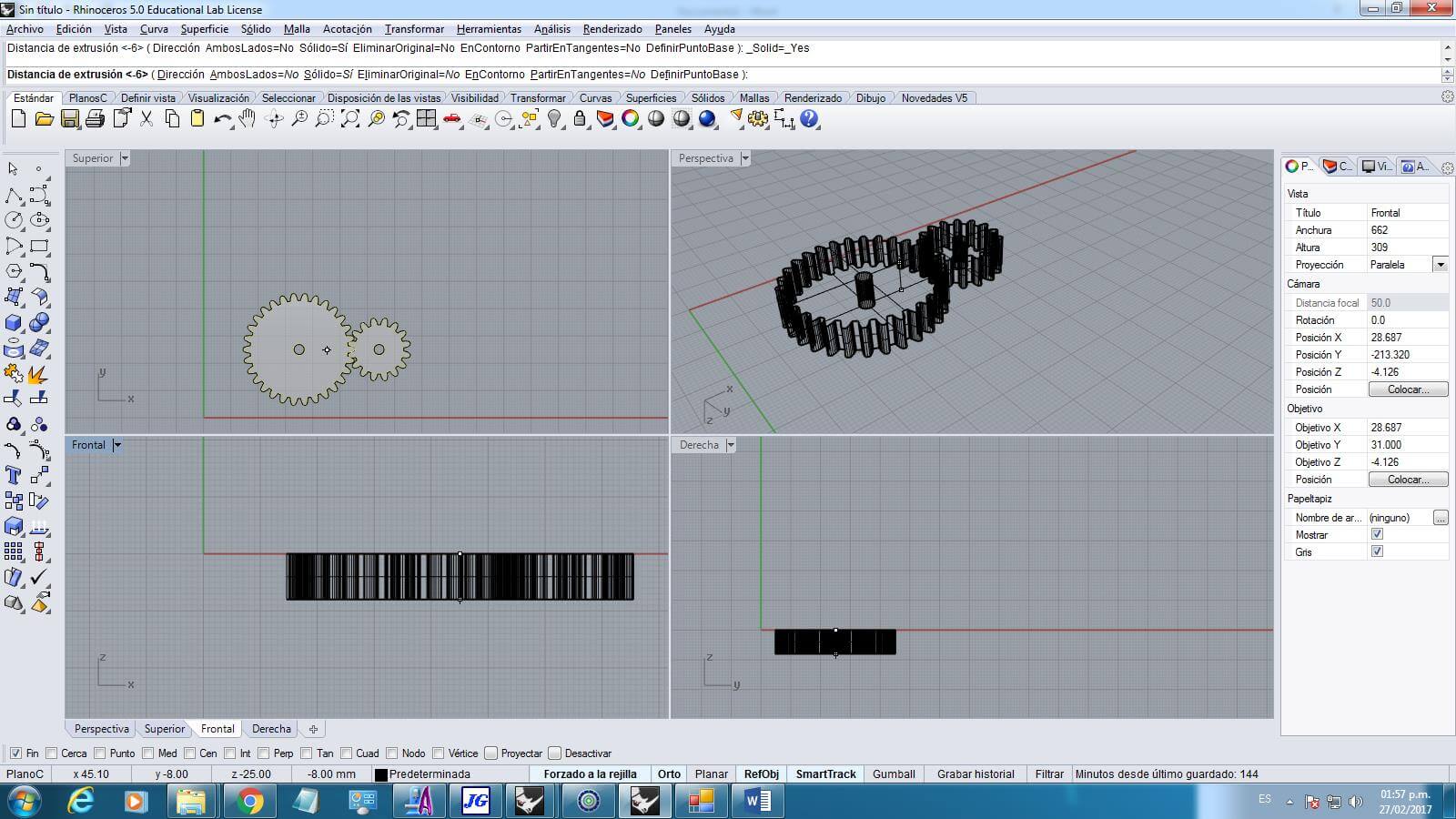
Then enter the thickness of the gear and the finish product is this
Advantages of Autocad:
-First develop the 2D design and then use tools to convert from 2D to 3D.
-Autocad is versatile to define dimensions, generate figures, presents tools for figures in 2D and 3D.
- Generates design sheet where you can dimension and place the 3D figures in standardized formats.
- Can be used to draw very fast sketches as your environment allows.
-Export files in STL and DXF
Disadvantages of autocad:
- Does not present mechanical design libraries
- It can design gears but it takes a lot of time.
-It does not have many formats to export to CNC, etc.
Advantages of Rhinoceros:
- First develop the 2D design and then use tools to convert from 2D to 3D
- Present different plugins to develop numerical control works.
- Has work views immediately.
- It has mechanical design bookstores.
- It has different formats for exporting files.
- Mechanical design time is very fast.
Disadvantage of Rhinoceros:
-It can not do different jobs at once. It becomes slow.
- Rhinoceros work with commands and this makes it more dynamic, but does not show a previous use of their commands like Autocad.