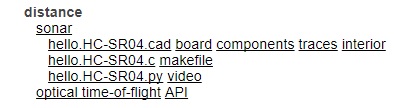
As you can see there are several input devices in which we can work. In my case I chose the DISTANCE SENSOR (SONAR). As you can see in the following figure, you have all the files needed for the activity: the "board" file and " components" serve us at the time of soldering the components; Files " traces" and "inner" are used for the machining of the PCB on the machine "LPKF S63", the first track circuit and the second is the cutting path. Besides files "make file" for engraving appear as the means we have available and the program "C".
STEP 2: CONSTRUCTION OF CONTROLLER CARD
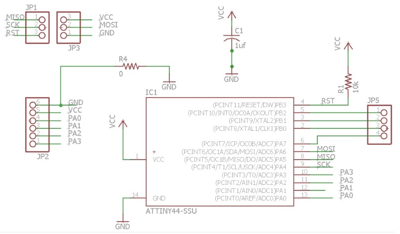
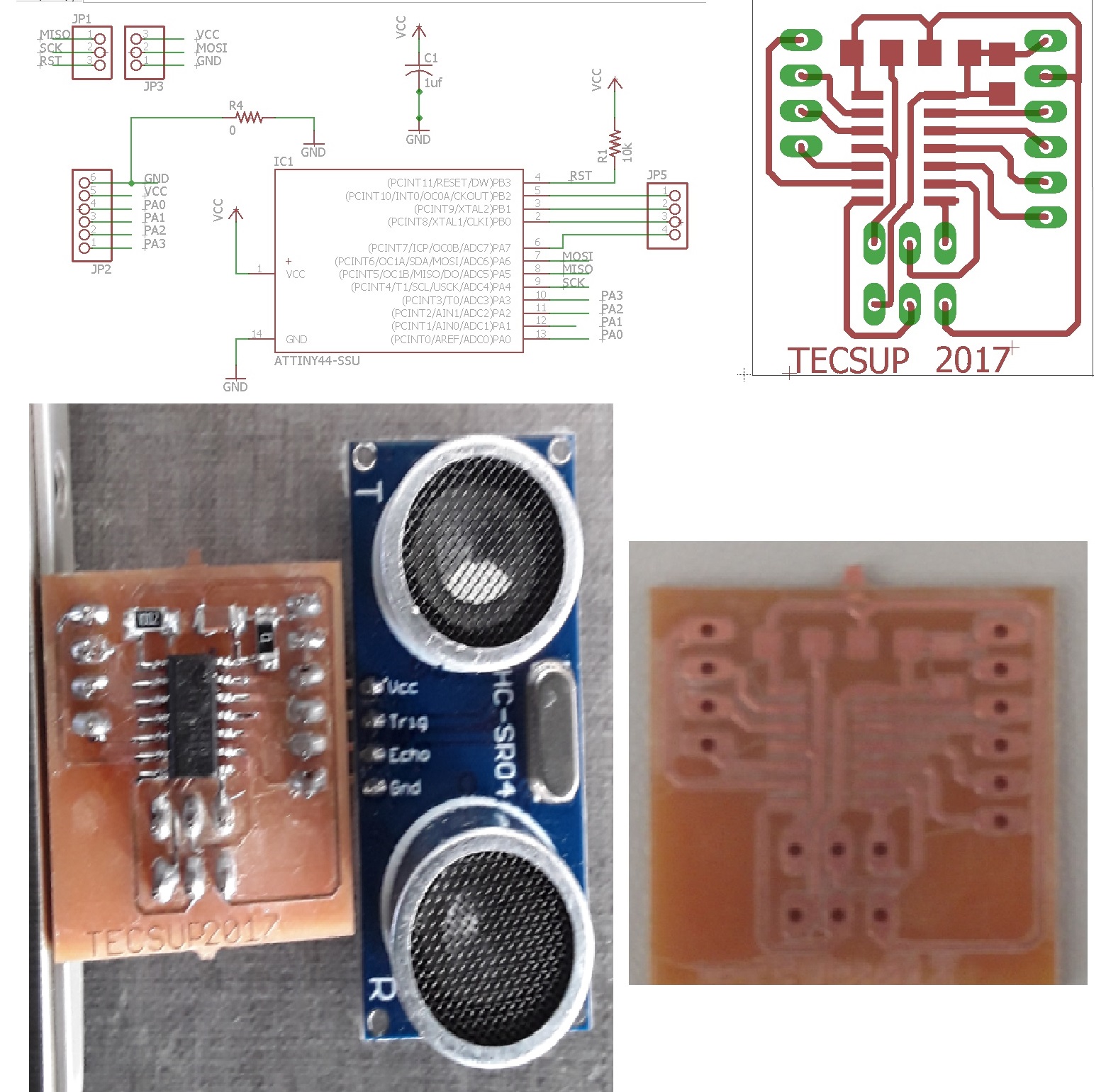
The design was done in Eagle in this program are generated layers and then imported from the software of the machine LPKF (in GERBER files).
Prepare the LPKF machine and adding the following cutters: "END MILL", "SPIRAL DRILL", "MICRO CUTTER", "UNIVERSAL CUTTER" and "CONTOUR ROUTING".
STEP 3: WELD COMPONENTS IN CARD
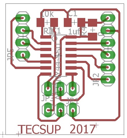
To weld the components of the card is necessary to use the file " components". It can be seen the position of the various components on the card. As can be shown in the figure, a Attiny 44 microcontroller was used.
For more information check this link ATtiny 44, where you can download the datasheet:
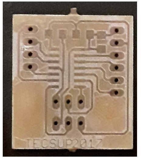
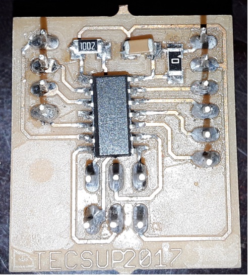
In the next picture the end result of the card with the components and soldiers shown.
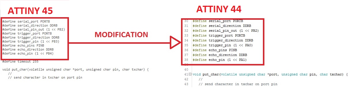
STEP 4: LOADING AND MODIFICATION OF PROGRAMME ATTINY 44
Modified the program for which to work with Attiny44. In the original design was worked with Attiny45.Then the program was uploaded using the Fabduino as an ISP programmer from the Linux terminal.
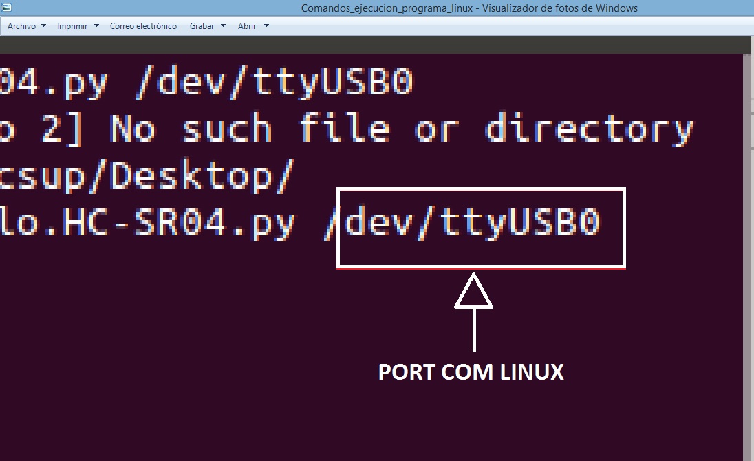
The disadvantage that I presented the execution of the program was to find the name of the COM port, The port in linux is found as ttyUSB0. as show that in figure:
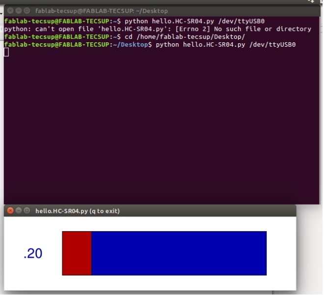
STEP 5: CHECKING THE OPERATION OF THE APPLICATION
Once the port is found, proceed to run the program as shown in the figure.