![]()
FABLAB SHENZHEN
FABLAB WUHAN
FABLAB TAIPEI
LITCHEE LAB
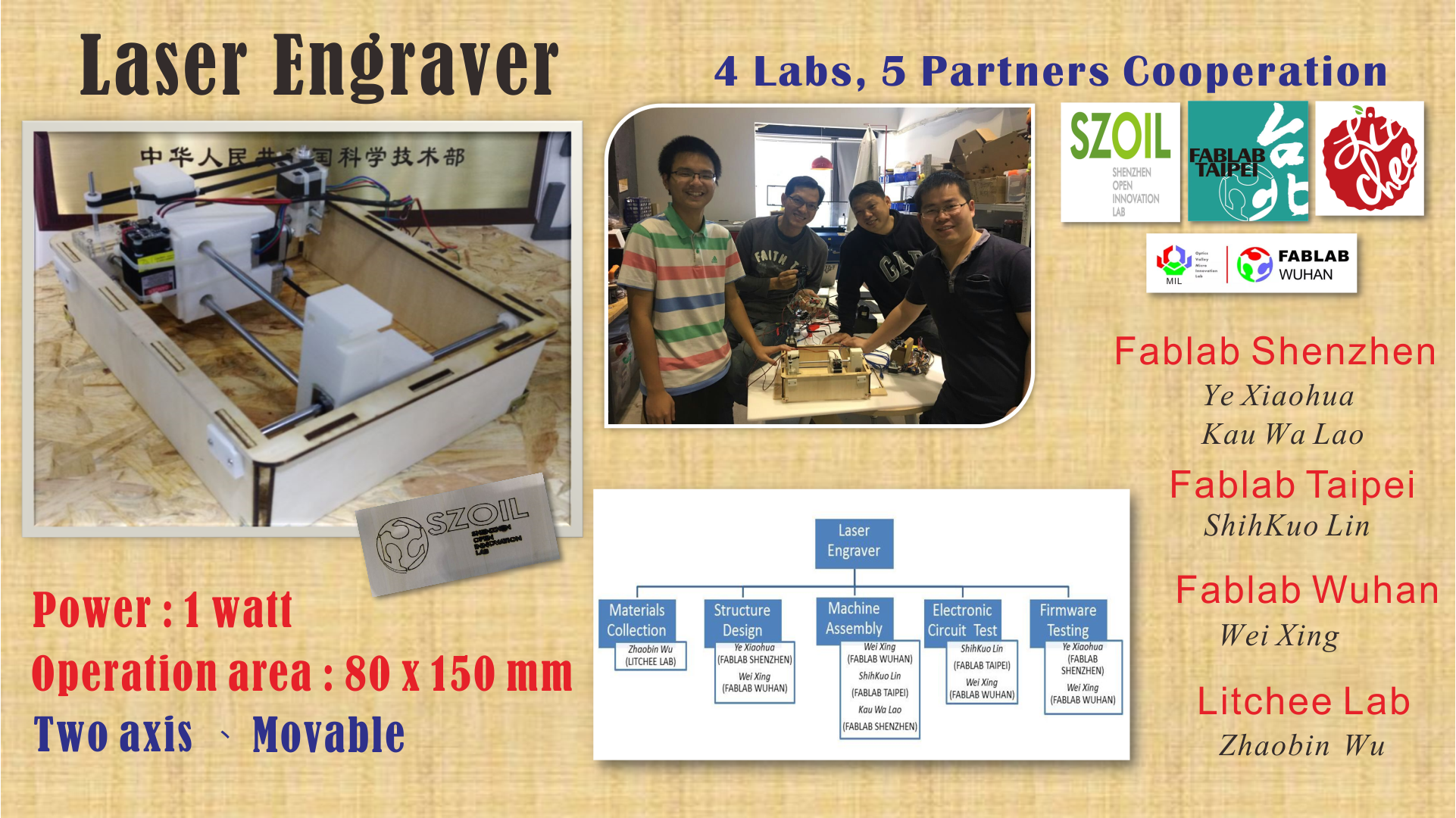
::Make The Machine -- Laser Engraver::
The finished laser engraver vedio is showed as follow:
Our team has five partners from four different fablabs. Since we decided to build the machine together in fablab Shenzhen, we discussed what machine we want to build and materials via online meeting one week in advance.
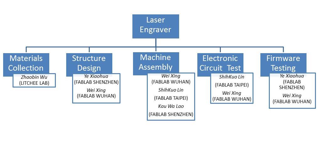
We decided to make a laser engraving machine. Building the machine is divided into several parts, and the work of each partner is assigned as follows:
● Mechanical Design
::Structure Design::
After we decided to make a laser engraving machine, Zhaobin Wu was responsible for collecting all the necessary materials. While we met in fablab Shenzhen, we quickly synthesized our ideas and drawing sketches on the white board.
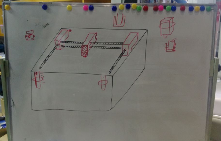
figure 1: Sketch of laser engraver.
Ye Xiaohua was responsible for designing parts of structures via Fusion360 as follow:

figure 2: Moving joint of laser engraver.
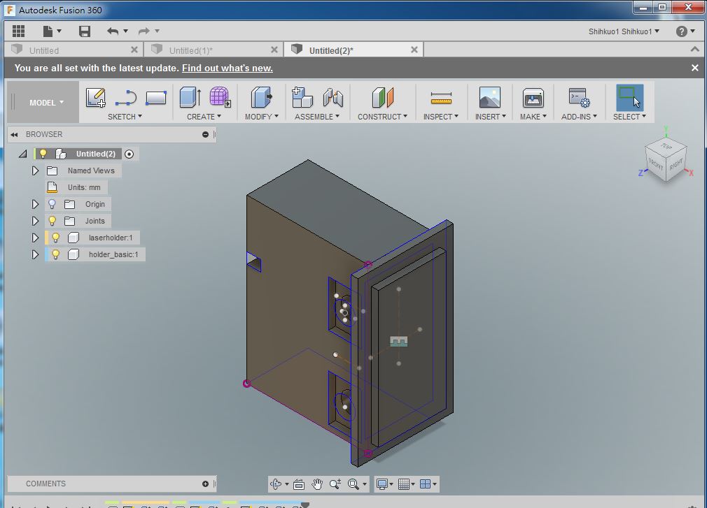
figure 3: Main joint of laser engraver.

figure 4: Case of laser engraver.
::Machine Assembly::
After assembling all the printed and cut components, we found there was not enough space at the bottom. So we corrected the height of the case.

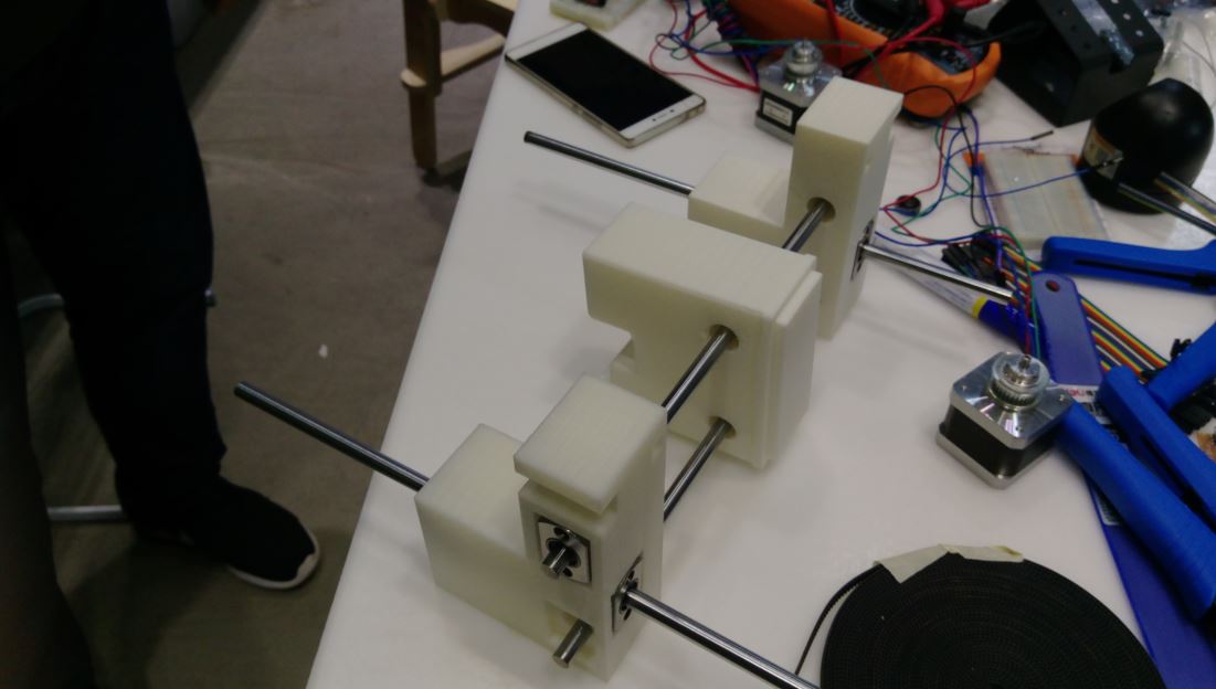


figure 5: Assembling the joints of laser engraver.
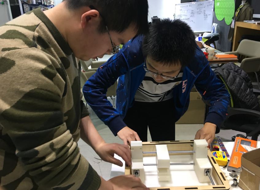
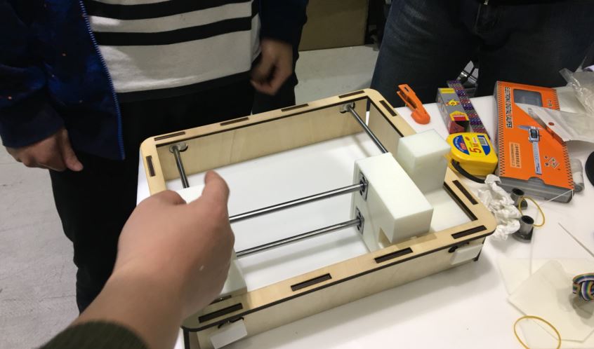
figure 6: There was not enough space at the bottom.
We found that it needed some small parts to fix the joints. After correcting and assembling all of parts, the structure looks good, and the slide rails moves smoothly.
::Electronic Circuit Testing::
The laser engraver we designed has two motors which control the movement of x and y axis. So we used arduino UNO as the central board and two pieces of "easy driver" as the motor driver. ShihKuo Lin was responsible for testing the electronic circuit.
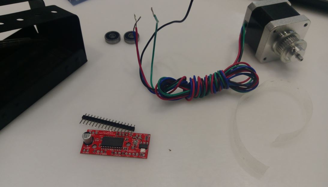
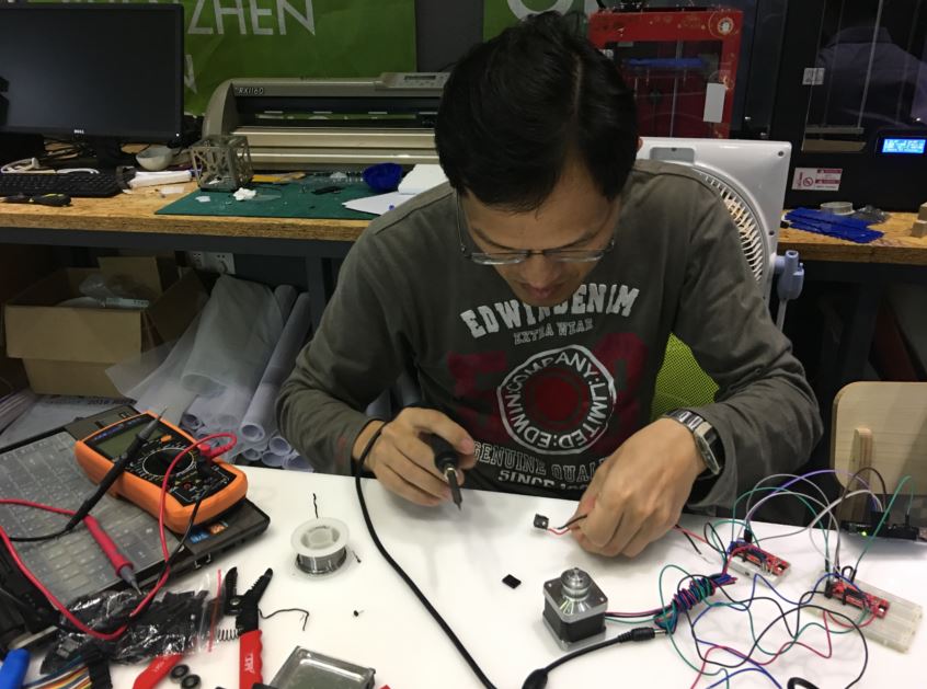
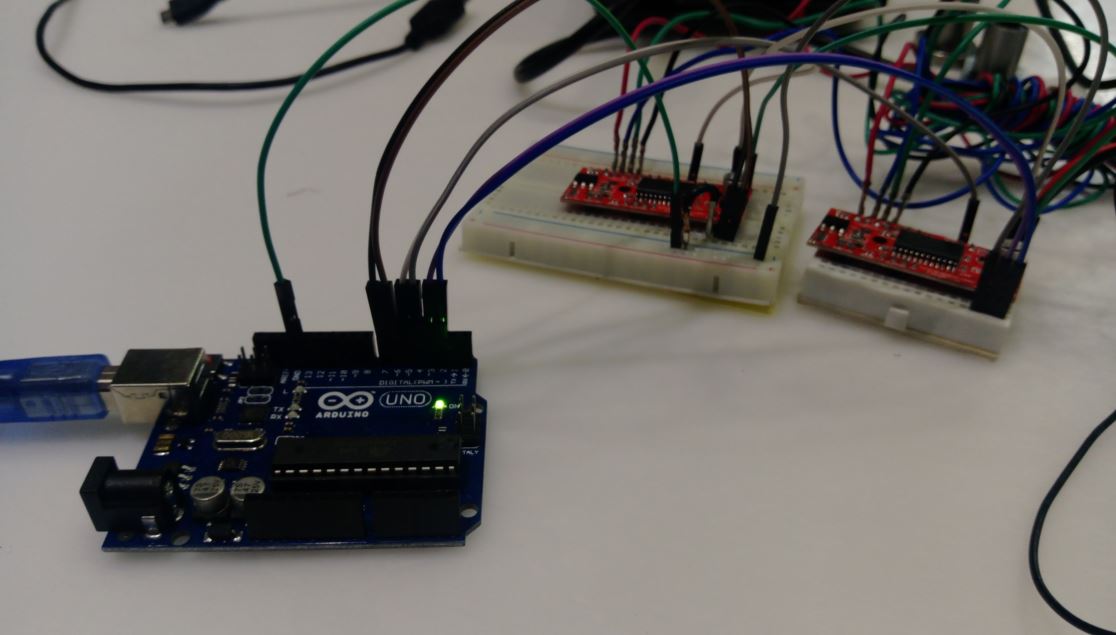
figure 7: Electronic circuit connection between arsuino UNO and easy driver.

figure 8: Electronic circuit connection between easy drivers and motors.
The vedio of testing motors is showed as follow:
After connecting and testing the electronic circuits, we assembled the motor circuits on the machine. There were some important parts we did not concern before. That is how to connect the connection between the motor and the connector and move along the axis. After a group discussion and testing, we designed a feasible way to connect the drive.

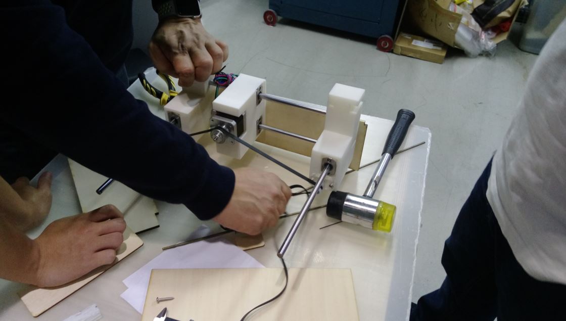
figure 9: Testing the possible solution of connecting the drive.
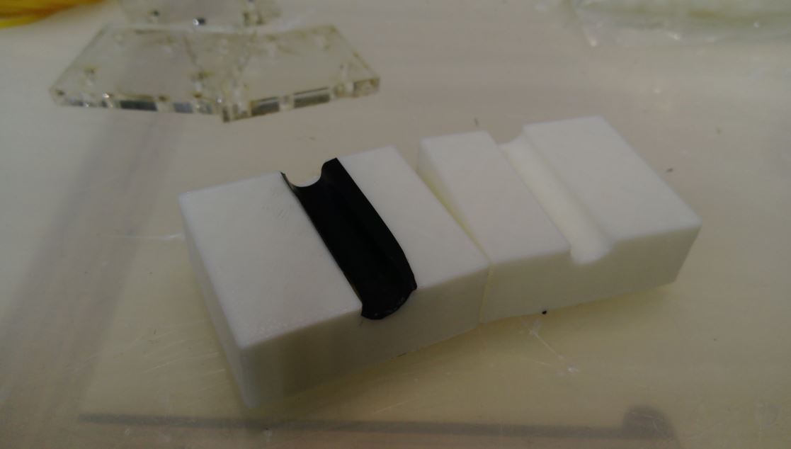
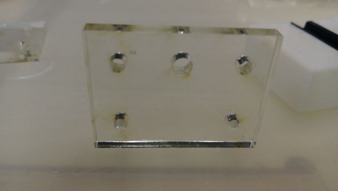
figure 10: Design piece of joints to fix the motors.


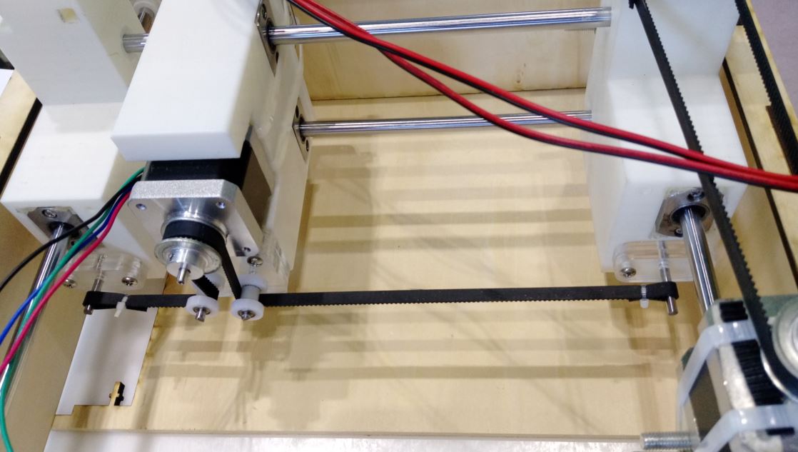
figure 11: Final solution of connecting the drive.
The vedio of testing connection the drive is showed as follow:
● Machine Design
After finishing mechanical design of the machine, we setup the laser head which the power has one watt.
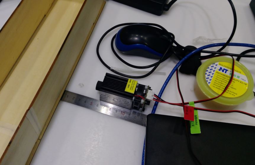
figure 12: Laser head and it's power is one watt.
::Firmware Testing::
Wei Xing and Ye Xiaohua were responsible for testing the firmware of the machine. Following the tutorial of introducing Grbl. We tried to use GrblPanel to control the machine. The motor was not going well at the beginning, and it took us half a day to discuss and test the hardware or firmware. We tried to use another program to test the electronic circuit connection of motors, and they worked well. So we recheck the firmware problem. After re-view the tutorial, we found the connecting rate should be setted to 115200, and we set 9600 before. After setting the connecting rate to 115200, the machine finially started running.
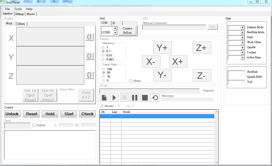
figure 13: GrblPanel.
We draw an 2D testing graphic via Inkskcape, and it could easy export nc formate file. Then we loaded the nc file on GrblPanel, but we met another problem. The laser did not follow the program turn on. So we view tutorial of M-Code and check the commands step by step of the program. We found that if we changed the code M03(Spindle ON) to M05(Spindle OFF), the laser was working properly.
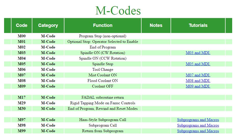
figure 14: M-Code sheet.
The result of first testing graphic was not good, it seemed like the circuit connection of y-axis motor connect wrong side. So we tried to change the connection of y-axis motor and it worked well.
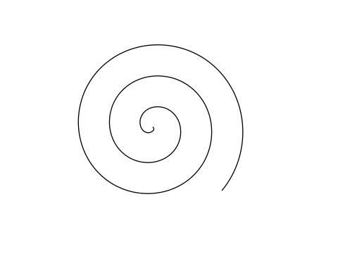
figure 15: First testing graphic.
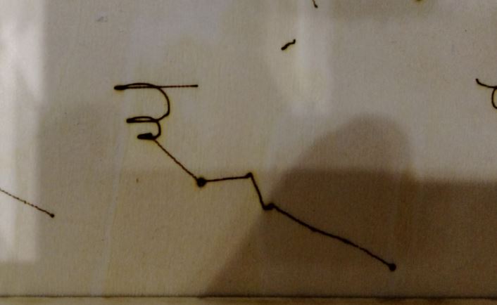
figure 16: The result of laser engraving the first testing graphic.
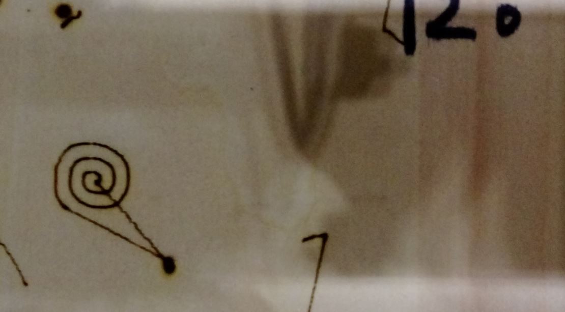
figure 17: Corrected test result.
Then we tested and found the working area was 80x150 mm. So we engraved the second graphic and the result showed as follow:
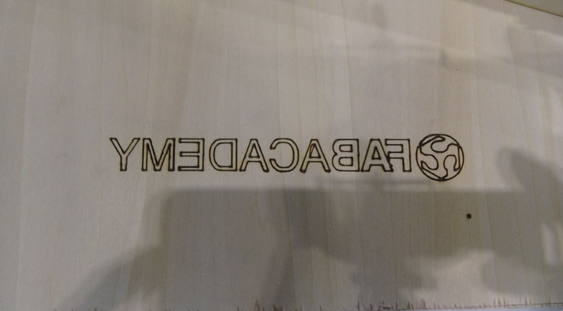
figure 18: Second graphic did not be mirrored before engraving.
We did not mirror the graphic before, so we corrected it and engraved again. Finally, we obtained a success result and finished our laser engraving machine.
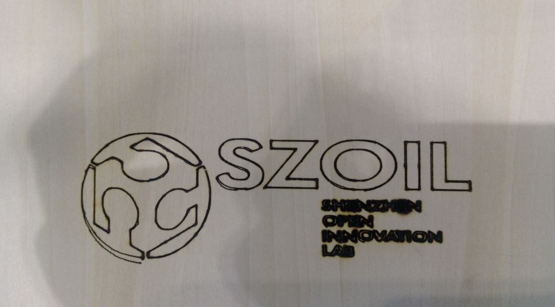
figure 19: After correcting the problems, the result looked good.
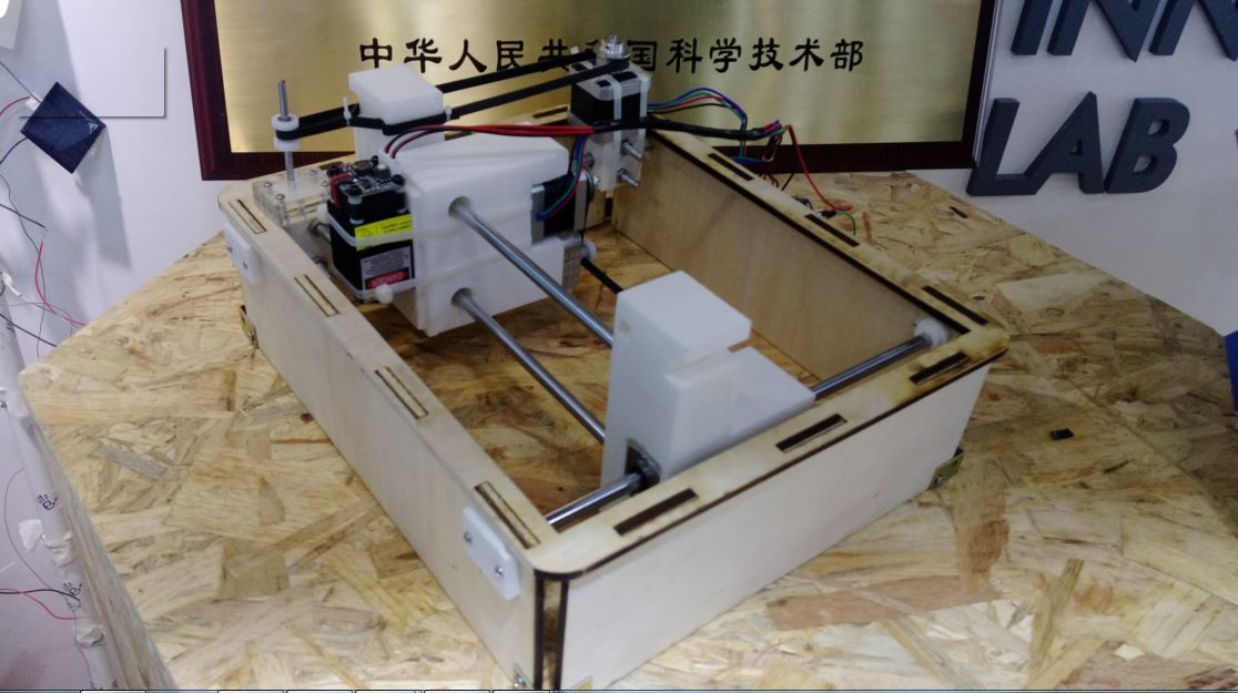
figure 20: Our laser engraving machine.
Future development opportunities for this project :
1. Protection cover : The laser is very dangerous, so we could add an protection cover to against the laser injury.
2. Redesign moving joint : The moving joints were to big, we could redesign the moving joints, so the operation area would bigger than before.
● Source file
1.Sheet of materials.
2.2D and 3D models of case and joints.
3.GrblPanel.
4.2D file (dxf) of the case..