The assignment
This week’s assignment was to write an application that interfaces with an input and/or output device made by the student, comparing as many tool options as possible.
The plan
I’m still troubleshooting the boards I designed on output and input weeks so, in order to have good time to work with applications and interfaces, I’ve decided to develop an interface for Neil’s analog microphone example board. And as soon as I have my own design from input week ready, I’ll apply it to it.
So the plan is to develop an interface for the Analog Microphone example board. For that board, Neil has developed a Python program that works as an interface, and displays the readings from the microphone, as a graph.
I would like that my interface displays not only the values is reading, but also simulates how the microphone inputs could work with a RGB led (the board I’ve been working with in output week). The idea is that the RGB led will change to a specific color according to a specific reading. That is simulated by having the background color of the interface changing according to the microphone readings.
For that, I'll:
- mill the analog microphone example board, traces and outline;
- solder all components;
- analyse Neil’s C program for that board;
- load C program into microcontroller through correspondent makefile;
- analyse Neil’s Python program for that board - which is already working as an interface;
- adapt the Python program to a Processing program - Processing has been recommended for beginners in class;
- add the extra feature of background color change to the interface Processing program;
- test it with Neil’s microphone example board;
- analyse and check what changes are needed for it to work with my own microphone board design;
- test it with my own microphone example board.
Testing with example board
I started by analysing Neil’s C and Python files for the microphone board, to understand how they call for each other as well as their roles in an interface application.
As I understood, the C program is collecting a series of readings from the microphone and storing them on the serial port. The Python program is reading the values from the serial port and editing them for visual communication (defining canvas, centering, creating graph line, etc.).

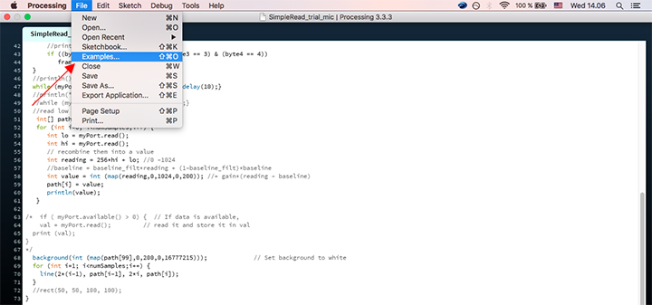
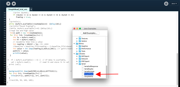
Based on this, I’ll adapt Neil’s Python program to Processing and add a background color to the canvas where the graph line of the readings of the microphone is being displayed. The background color will vary according to the readings. I started with a built in example from Processing.
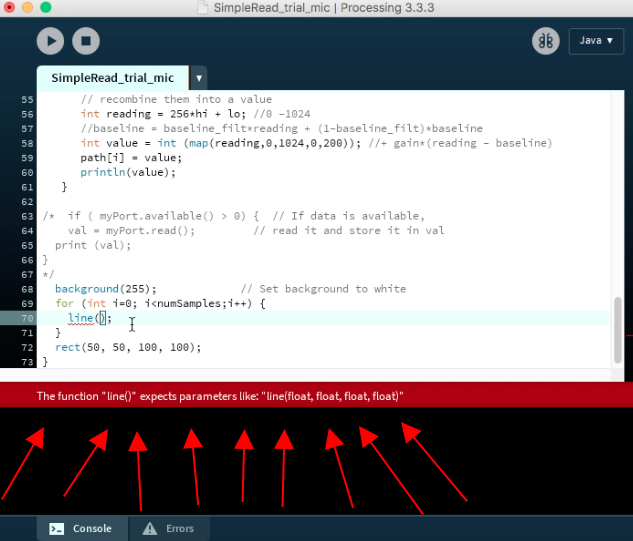
I then copied the Python program from Neil into Processing and started “translating”. The syntax is slightly different, so it’s good to keep an eye on the “complaint” bar.
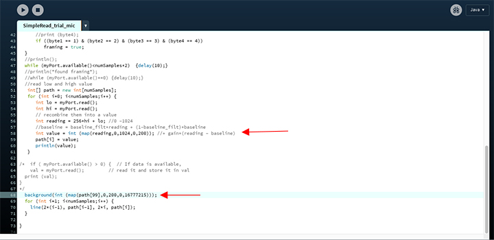
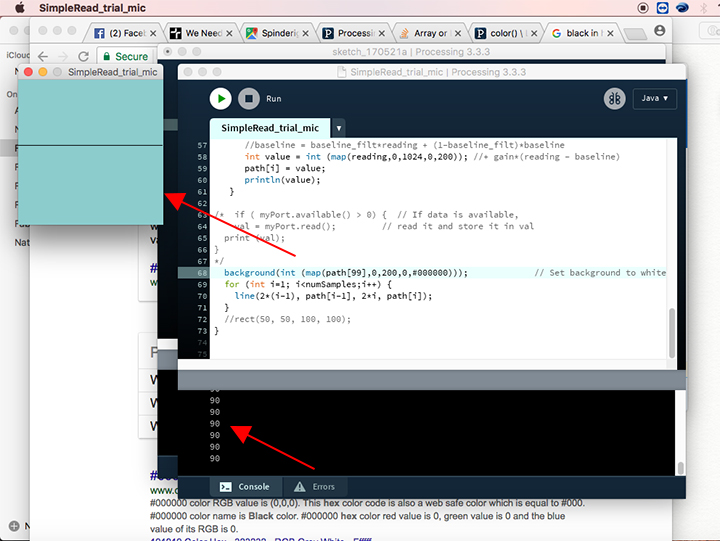
When I was done with the “translation”, started looking into how to make the background color change according to the readings. The map function in Processing proved to be really useful. I used it both in translating the graph line from Python and in setting the background color according to the mic readings. On the graph line, it “scales” the interval 0-1024 (possible reading values from mic) to 0-200 interval (size of the canvas we have defined). On setting the background color, it “scales” from the interval 0-200 to 0-16777215 (16777215 is the decimal value for FFFFFF hexadecimal value, which corresponds to the white color). This way, both the graph line and the background color are a visual expression of the readings.
I tested with Neil’s example board, but has you can read in week 13(link), the microphone component was not well soldered. So it could still register different values and show that the interface program was working. However, the values it was reading were in a very narrow interval, no matter how high or low the background noise was.
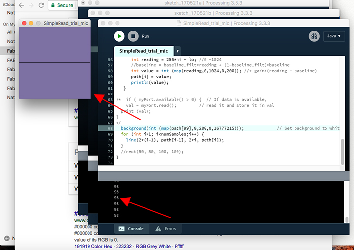
Applying the interface program to my own board
After a couple of challenges, I finally managed to have my own design of a analog microphone board, see week 13.
I connected the board to the computer through the bridge board (like in the end of week 13), and run the processing program.
I then started a youtube clip of the Imperial March. Everything worked as expected.
Working towards the final project
This week was great to better understand how the readings of the mic work. Trying a new software and different applications for the same board was an eye opener for the endless possibilities and applications of this course.
By now the final project is quite defined. It will consist of a e-textile modular system, where for FabAcademy I’ll develop 4 initial modules - power, wire, input, output. The input module will be an analog mic, that can communicate with the output module, an LED. Due to time constraints, I’ll keep the output module as a simple LED. But this week as been great to simulate the possibility of integrating an RGB led as another output module in the future.
Main learnings from this week
I had a good feeling with Processing, the library/examples are really helpful and friendly towards self learning. So far, I have been doing my code in “clean” C, but got curious/motivated to look into Arduino programming, as I heard is similar, with built-in libraries and examples. I’ll be taking an intensive online course over summer.
Files
Files regarding the microphone board can be found in the end of week 13 (link). You can find the files regarding this week below. To download them, right click with the mouse and chose “save as”.
