The assignment
This week's asignment was to add an output device to a microcontroller board I've designed and program it to do something.
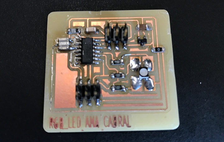
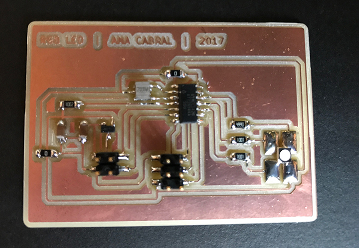
RGB led board
I decided to work with an RGB led, that can be used for the machine we are designing in group, and most likely in my final project as well.
The process
The process will be similar to what we have been doing in previous weeks.
- decide which changes are meaningful to make to Neil's example board or design a board from scratch;
- develop the schematics for the board, I have been doing it in Kicad;
- create the layout for the board in Kicad, based on the netlist generated from the schematics;
- export the layout as an SVG file and use a vector drawing program to edit the traces and outline files for milling - normally PNG files that are then used in FabModules;
- mill the board;
- solder the components;
- develop/adapt C code and makefile in order to program the board's microcontroller;
- power the board, connect it to the usbtiny programmer and load the program;
- test that the board works as expected.
It's a long process that is becoming more and more familiar.
1st attempt
Looking at what meaningful modifications could be made to Neil's example boards, I have decided to add a attiny44 instead of a attiny45. In this way, I would have extra pins, in case the board should be used in the machine design group assignment. Meaning, I would have then the 2 extra pins to communicate with the Gestalt boards.
I made a big mistake when developing the schematics for this board. I used a 2x3 regular header, instead of ISP header, misplacing all pins (MISO, MOSI, RESET, SCK, VCC and Ground). I went a complete loop in the process without being aware of it, only when debugging on the programming phase, got aware of the mistake.
So the board was not used in the machine design assignment.
2nd attempt
I went back to the schematics in Kicad, substituted the 2x3 regular header by a ISP header, updated the current netlist and created a new layout. Wwnt through the whole process again and still got problems when trying to load the program into the RGB led board microcontroller.
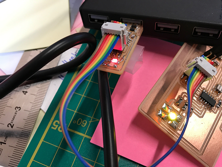
It was already visible something was wrong when plugged the board to the battery and usbtiny programmer and RGB led was lightning up. Looking at the board layout, figured out RGB led was sharing pins with the ISP header.
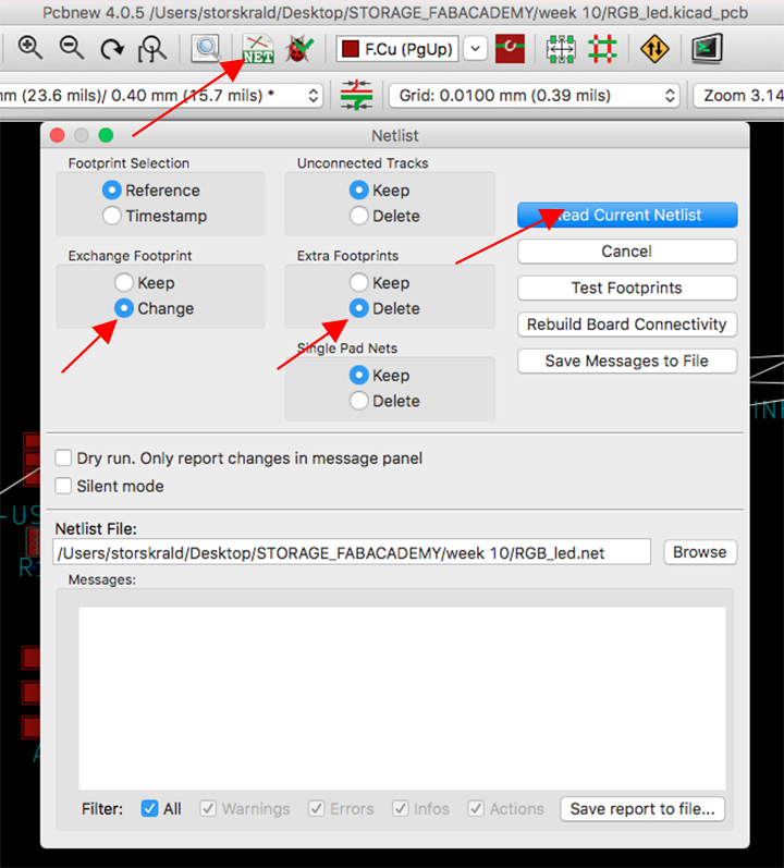
So, when importing the changes from the new netlist into the existing layout, I didn't tick some important options, so the connectiosn between the components was never truly updated.
So, remember to always tick the boxes I point to in the picture below, to make sure your netlist gets updated in your layout file, and that the previous netlist is deleted/stops being considered.
I used jumper wires, but that board was beyond salvation...

3rd attempt
So I went back to Kicad, this time making use of the right ISP header when working on the schematics and being extremely careful ticking the right options when updatng the curent netlist.
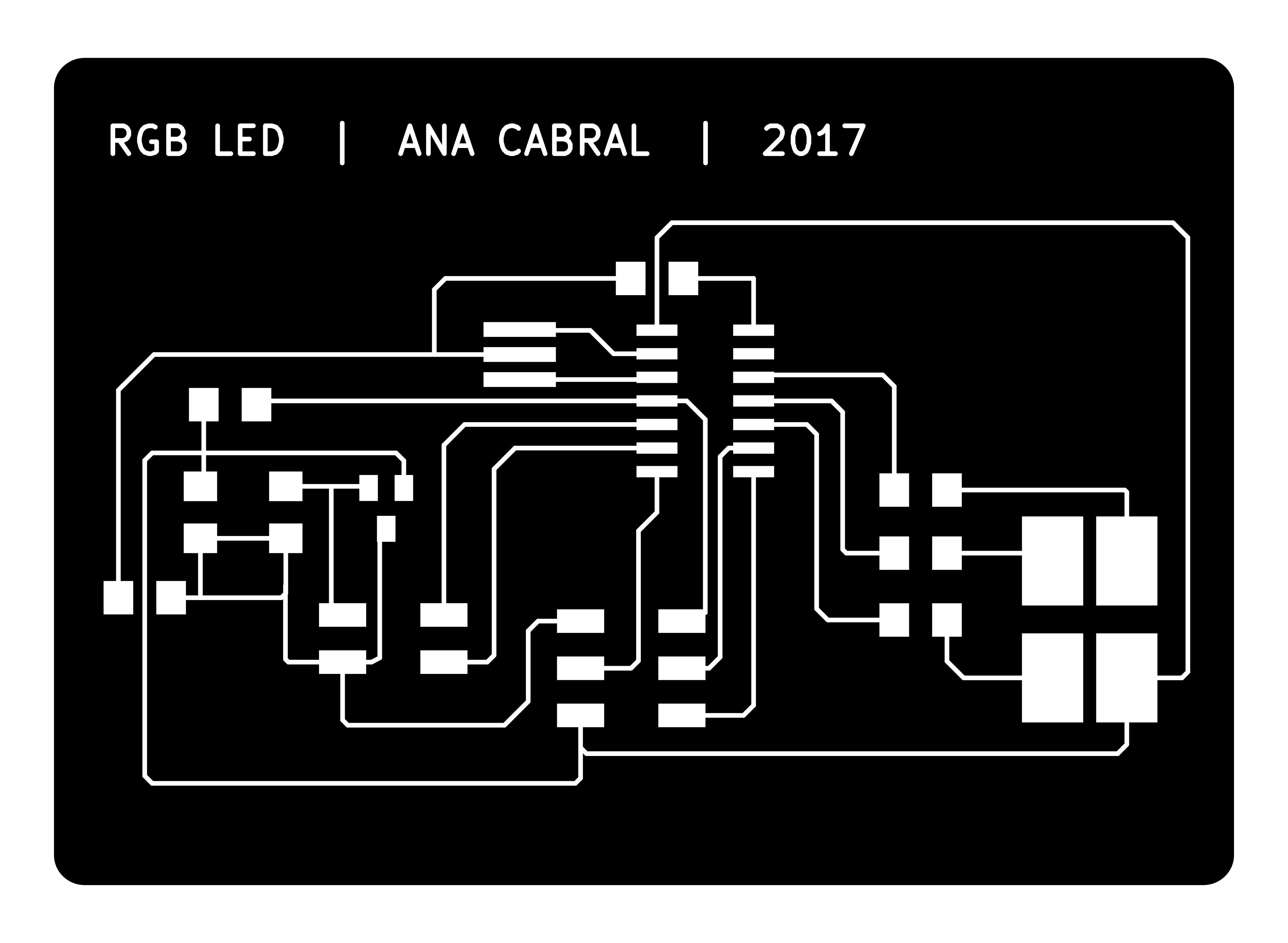
I made a new layout for the RGB led board, this time I even managed to integrate the jumper in Kicad - normally I would integrate the jumper in Inkscape.
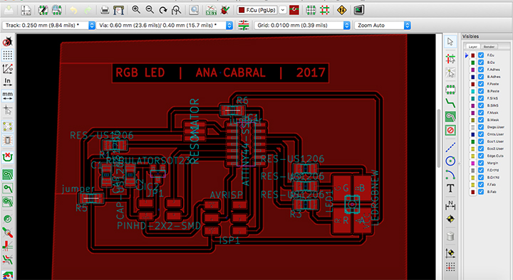
Both schematics and layout files are available for downloading in the end of this page.
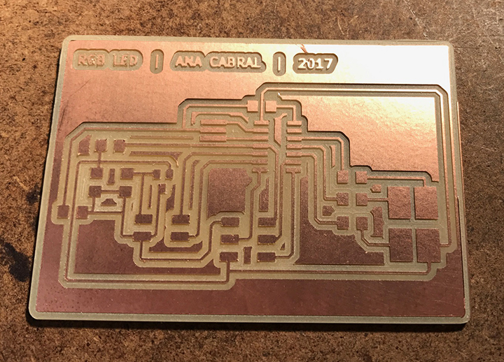
I milled the board as usual, through FabModules, first the traces with 1/64 inch bit and then the outline with the 1/32 inch bit.
You can find the editable .svg file, as well as the traces and outline files as PNG for downloading in the end of the page.
Proceeded by soldering the components.
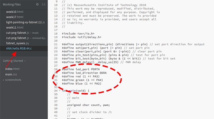
Then I looked into the programming for the board. I downloaded the C and makefile from Neil's RGB example board and made the necessary changes.
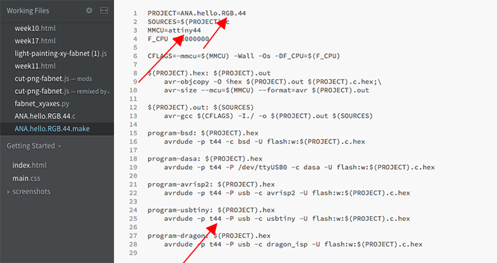
My board makes use of a attiny44, so I changed that in the makefile - I also updated the c and makefile namem so I had to update the Project it links to.
In Neil's C file, I updated the led pins. See below.

I saved both files and prepared to load the C program into the RGB led board.
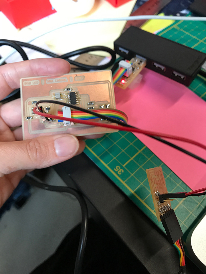
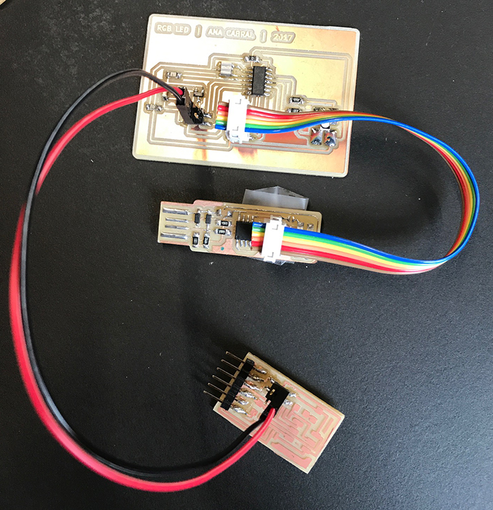
For powering the boards, I'll be using the bus bridge board, from network week, where I only soldered the FTDI header and a 4 pin header. Before powering the boards, I checked for continuity for Ground and VCC between boards.
I connect all boards - RGB led board, bus bridge board and usbtiny programmer and loaded the C program.
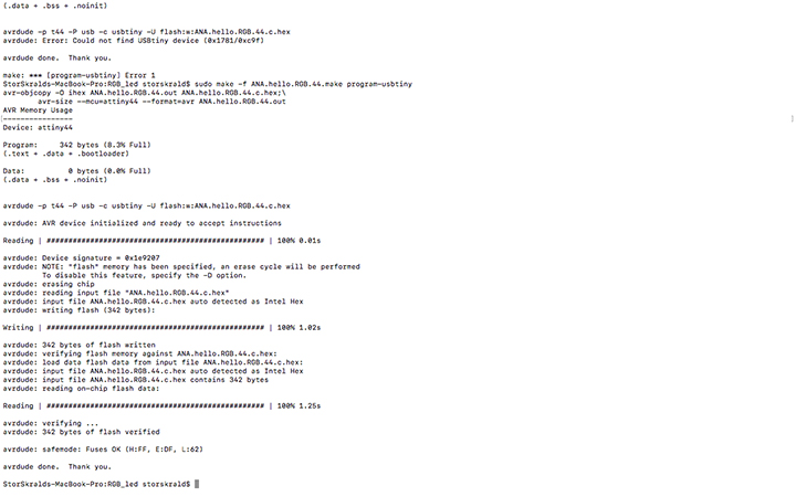
To do that, I wrote "sudo make ANA.hello.RGB.44.make program-usbtiny". All worked, fuses ok.
Below, you can see a small movie showing how the program works.
Main learnings from this week
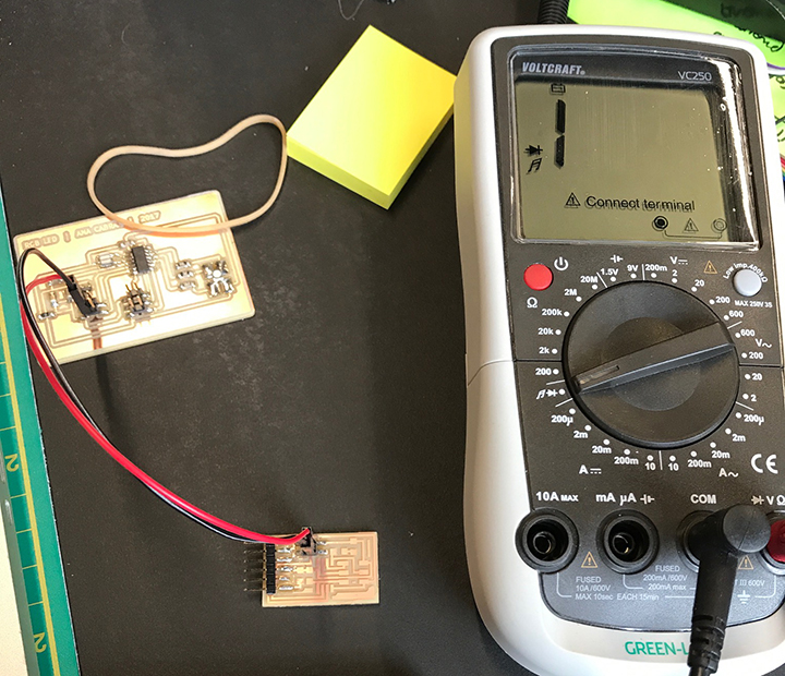
It’s really good that every second week we get a chance to work more with electronics design, electronics production and embedded programming. Slowly, the process is becoming familiar and sinking in. Though, if one becomes too confident, it can happen like it happened to me this week.. where some silly mistakes ended up taking all of my time. A way to avoid it would have been to be more keen on double checking schematics, layouts, checking connections on the board, etc. I have learnt my lesson, the process with the last board went very fast and using the multimeter became an integrated routine (I feel like having a multimeter in my purse, just like I have my phone). My new best friend!
Files
All files regarding this week can be found here. To download the files, right click with the mouse and chose “save as”.
RGBLED_SCHEMATICS and RGBLED_SCHEMATICS
SVG_BOARD, PNG_TRACES and PNG_OUTLINES
ANA_C and ANA_MAKEFILE
