Exercise 10
Output Devices
This week, we are making output devices.
It is an interesting and also a brain-teasing week.
RGB LED
I'll be using what Neil has for us as a guideline. I'll be using Eagle to draw up the schematics and convert it into board. click here to refer to the Eagle exercise.
Neil's guideline.

Eagle design
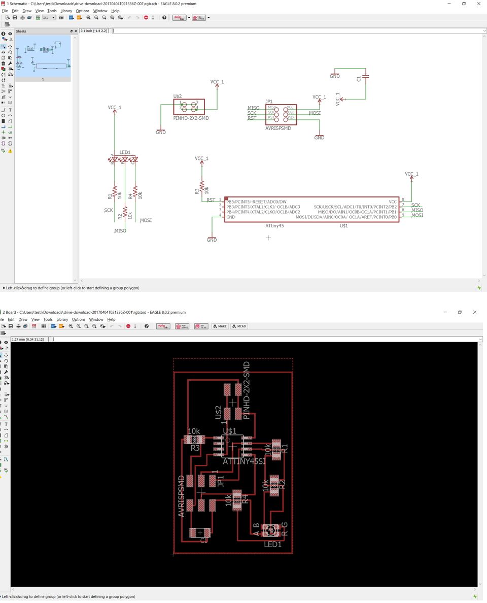
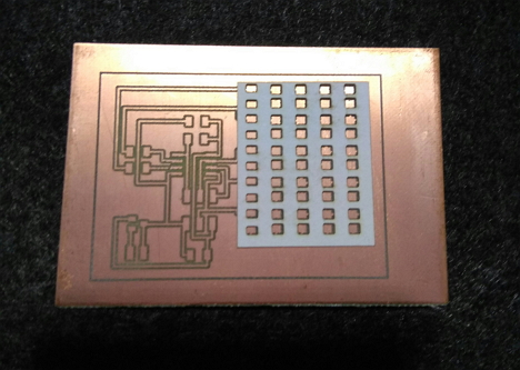
After milling the board, I need to take note of the position of my RGB LED.
Then I cleaned by board as usual and soldered the components.
Next, I do a connectivity test using the multimeter.
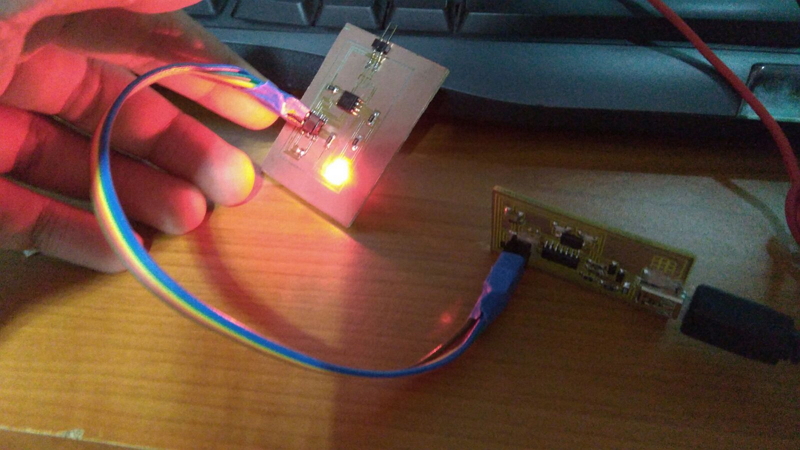
Then I connect my RGB board with my FabISP and using Arduino IDE to program the chip with the code below. As our RGB LED is a common Anode, I had to define the common anode so that it can produce the correct colour!
//Declaring the Pins to names that I can understand, I can give different name varables
int redPin = PB2;
int greenPin = PB0;
int bluePin = PB1;

//uncomment this line if using a Common Anode LED, I am using a Common Anode, therefore I need to uncomment the line below
define COMMON_ANODE

void setup()
{
//Setting the pins to be an OUTPUT PIN
  pinMode(redPin, OUTPUT);
  pinMode(greenPin, OUTPUT);
  pinMode(bluePin, OUTPUT);
}

void loop()
{

  setColor(255, 0, 0);  // red
  delay(1000); //Delay for 1 sec before changing colour
  setColor(0, 255, 0);  // green
  delay(1000);
  setColor(0, 0, 255);  // blue
  delay(1000);
  setColor(255, 255, 0);  // yellow
  delay(1000);
  setColor(80, 0, 80);  // purple
  delay(1000);
  setColor(0, 255, 255);  // aqua
  delay(1000);

  //I can set more colours after this or using the RGB color circle to find a colour you want! PS: Black light will turn off the LED instead :P
}

void setColor(int red, int green, int blue)
{
  #ifdef COMMON_ANODE
    red = 255 - red;
    green = 255 - green;
    blue = 255 - blue;
  #endif
  analogWrite(redPin, red);
  analogWrite(greenPin, green);
  analogWrite(bluePin, blue);
}
Video and Hero Shot of my RGB LED
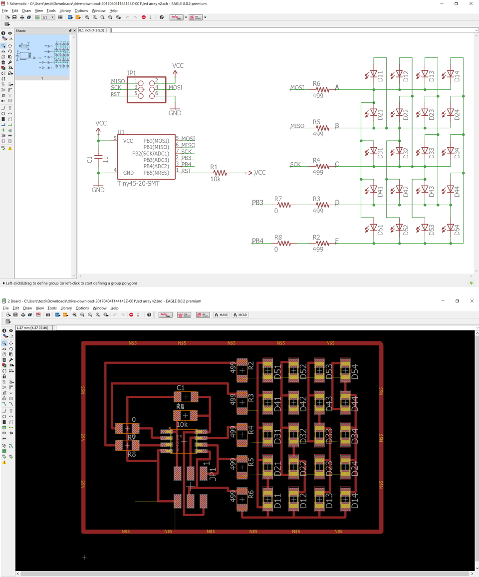
Charlie Plexing
I would like to credit my guru, Steven Chew for showing his charlie plexing and I decided to follow his guide from 2016.
I traced the paper backing on the circuit board and using Adobe Illustrator to create the cut lines.
Then I used the laser cutter to cut out the design.
While soldering, I need to take note of the LEDS positioning and the common ground.
Designed the circuits in Eagle
Video of Charlie Plexing in action:
Neil's version off the fabacademy.
I was curious, hence I played around on the delay and cycle to slow it down, this is how it will produce.
Code:
// hello.array.44.c
//
// Charlieplex LED array hello-world
//
// Neil Gershenfeld
// 11/13/10
//
// (c) Massachusetts Institute of Technology 2010
// This work may be reproduced, modified, distributed,
// performed, and displayed for any purpose. Copyright is
// retained and must be preserved. The work is provided
// as is; no warranty is provided, and users accept all
// liability.
//

#include < avr/io.h>
#include < util/delay.h>

#define output(directions,pin) (directions |= pin) // set port direction for output
#define input(directions,pin) (directions &= (~pin)) // set port direction for input
#define set(port,pin) (port |= pin) // set port pin
#define clear(port,pin) (port &= (~pin)) // clear port pin
#define pin_test(pins,pin) (pins & pin) // test for port pin
#define bit_test(byte,bit) (byte & (1 << bit)) // test for bit set

#define led_delay() _delay_ms(1) // LED delay

#define led_port PORTA
#define led_direction DDRA

#define A (1 << PA1) // row 1
#define B (1 << PA2) // row 2
#define C (1 << PA3) // row 3
#define D (1 << PA4) // row 4
#define E (1 << PA5) // row 5

void flash(uint8_t from, uint8_t to, uint8_t delay) {
   //
   // source from, sink to, flash
   //
   static uint8_t i;
   set(led_port,from);
   clear(led_port,to);
   output(led_direction,from);
   output(led_direction,to);
   for (i = 0; i < delay; ++i)
       led_delay();
   input(led_direction,from);
   input(led_direction,to);
   }

void led_cycle(uint8_t number, uint8_t delay) {
   //
   // cycle through LEDs
   //
   uint8_t i;
   for (i = 0; i < number; ++i) {
      flash(B,A,delay);
      flash(C,A,delay);
      flash(D,A,delay);
      flash(E,A,delay);
      flash(A,B,delay);
      flash(C,B,delay);
      flash(D,B,delay);
      flash(E,B,delay);
      flash(A,C,delay);
      flash(B,C,delay);
      flash(D,C,delay);
      flash(E,C,delay);
      flash(A,D,delay);
      flash(B,D,delay);
      flash(C,D,delay);
      flash(E,D,delay);
      flash(A,E,delay);
      flash(B,E,delay);
      flash(C,E,delay);
      flash(D,E,delay);
      }
   }

int main(void) {
   //
   // set clock divider to /1
   //
   CLKPR = (1 << CLKPCE);
   CLKPR = (0 << CLKPS3) | (0 << CLKPS2) | (0 << CLKPS1) | (0 << CLKPS0);
   //
   // main loop
   //
   while (1) {

   //I am editing the following codes to show it slow down
      led_cycle(5,200);
      led_cycle(5,150);
      led_cycle(5,100);
      }
   }
LCD
As time was abit of a constrain this week I was only able to design it only. I will look into it when I have more time.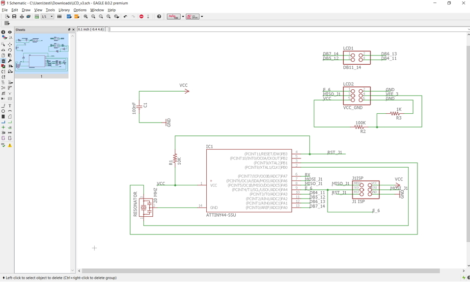
My Thoughts
I am quite weak at board designing, I have difficulty in designing complicated boards. But I do see a pattern in the Board designing and will put in some effort in creating my own Board for my final project.
I'm glad that I am able to learn how to make my RGB board as it would come in handy for my final project.
Downloads
RGB: herePaper PNG: here
Modded Neil Code: here
EAGLE Files: RGB (here), CHARLIEPLEXNG (here)