Exercise 4 - Electronics Production
Neil's ISP44
This is my first time working on milling and soldering Suface Mount Board (SMB) electronics.
To be honest, I'm both excited and really anxious on how it would turn out!
You can find the jpg file: here
Eagle PCB Designer
Eagle is a Printed Circuit Board (PCB) designer tool by Autodesk.
First thing first, I download the jpg image from Neil.
Invert the image using Inkscape, then I used Paint to save it as BMP Monochrome.
Then I import it into Eagle to be processed.
First, I created a new Project and named it as "NeilFabisp" & I created a board from there and I imported the BMP.
One thing that our guru mentioned to us, that the processed BMP has an issue of "sliced" image instead of a whole thing and encouraged use to create from scratch.This is something I will do in the near future.
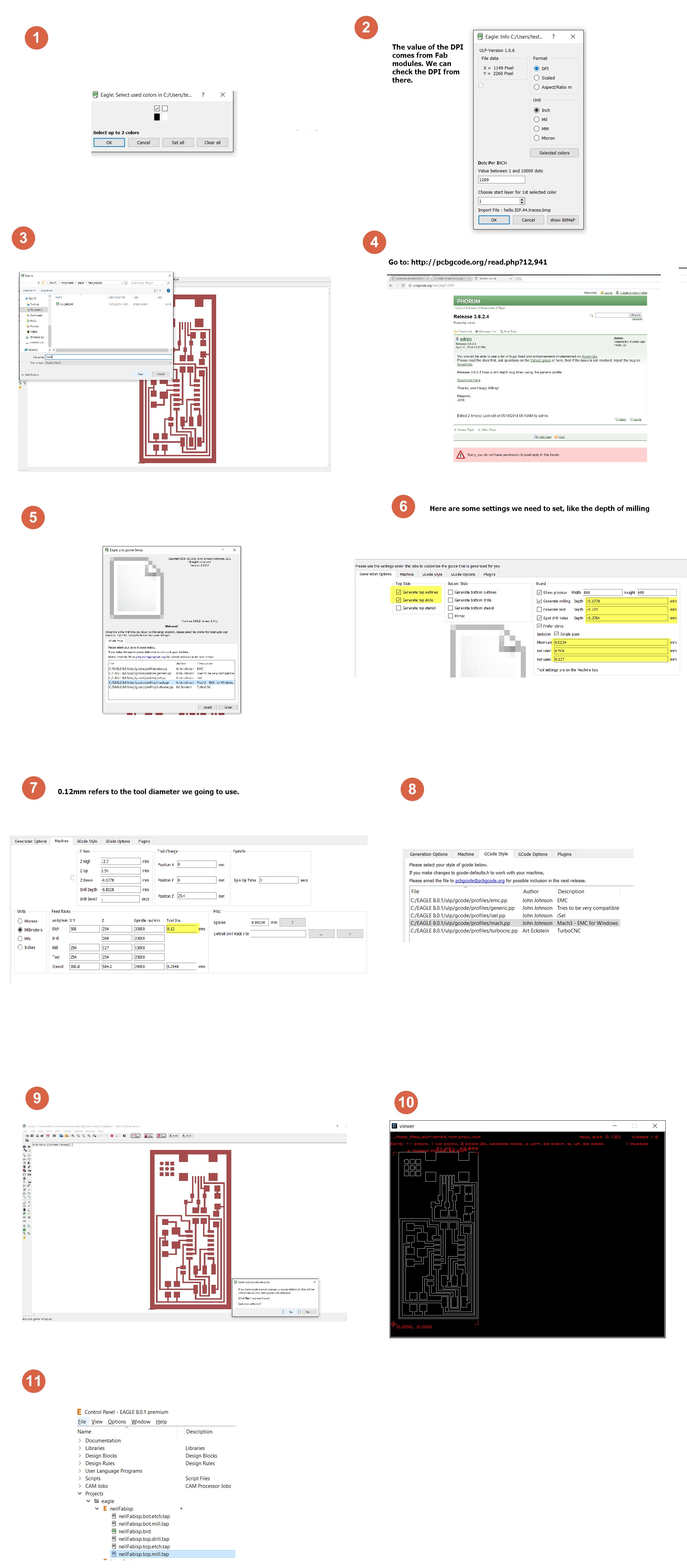
Additional Plugin: PCB to GCode (The reason why we need this is because our milling machine that we use and learn only reads gCode)
The following are the steps I've done when importing the Neil's FabISP
Click image to enlarge
Milling & Soldering
First, I will need to setup the milling machine, selecting the correct bit to mill the board. We've selected 0.12mm and equip the milling machine, we have to be cautious as the bit is sharp and worrying it will be blunt if dropped.
Next, We will load the file, neilisp.top.etch.tap into the CNC USB CONTROLLER software that we are using at T14 FabLab.
Then we mount our PCB on the bed of the milling machine and using the software Directional Axis and adjust the tool tip to the XY, 00 of the board and comeparing to the visual guide on the software. Lock and set the XY of the machine, slowly lowering the Z axis and check for the spacing between tip of the tool and the board by using a piece of paper. This action was very nerve wrecking as I was very worried that I would "over lowering" the tool causing the tip to blunt.
Going as close as -0.015mm(stated on the software), which is literally on the surface of the PCB Board, and if we minus away the -0.177mm mill depth settings, we are suppose to be able to mill the PCB!
Click image to enlarge
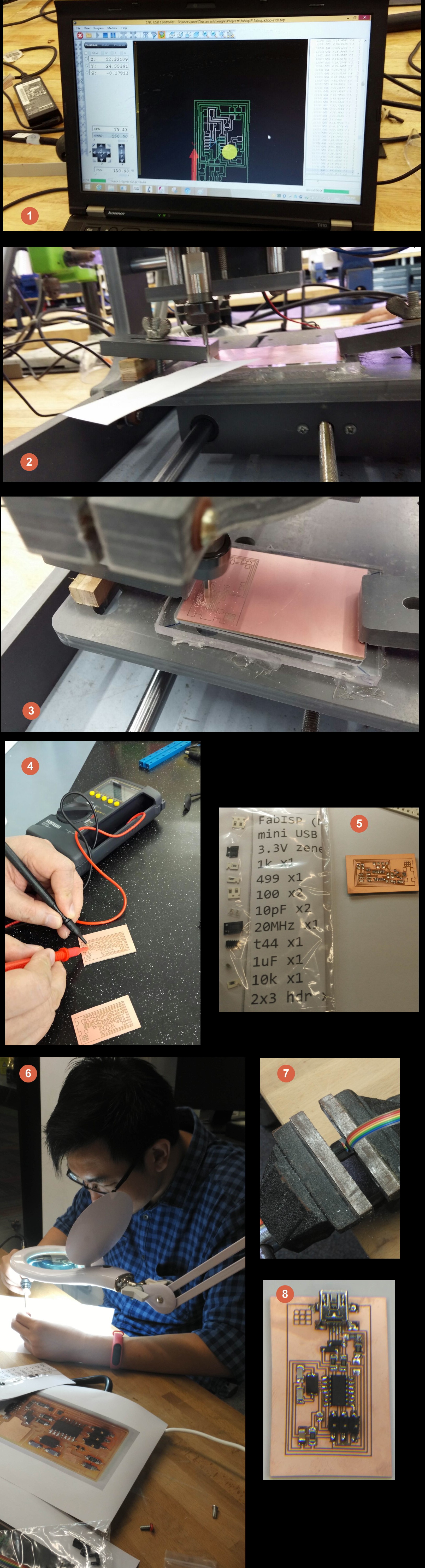
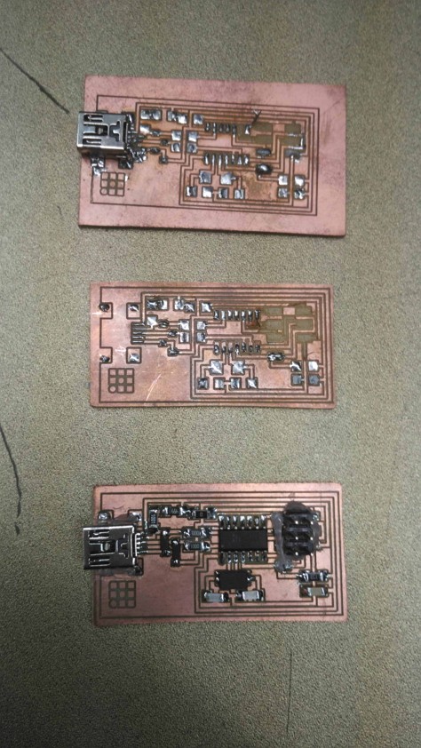
After milling, my Local Guru, Dorville prepared a set of the components for us to solder it on the PCB. It was a challenge as the tracks were so tiny! We had to use a sharp tip soldering iron and magnifiying glass to solder the PCB.
Programming
Warning, Wall of text, rants and frustration, if you want to see the TLDR; version, click here
I am using Windows 10 based Laptop, thus, I followed the instructions of programming my FABISP, which I think is inadequate for me, I couldn't really understand.
After installing, I tried plugging in my FABISP and I was hit by an error, UNKNOWN USB DEVICE (DEVICE DESCRIPTOR REQUEST FAILED
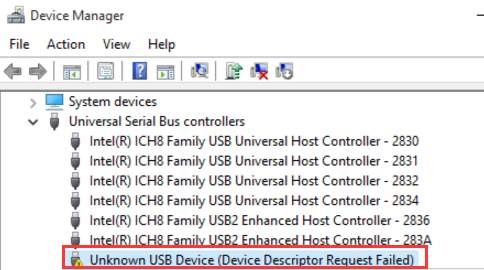
I began to troubleshoot my board and realised I mis-soldered/mis-aligned a one of the leg on the Mini USB.
I tried to remove the tiny legs without the help of the hot gun and failed miserably. The copper tracks fell off! So Frustrating!
When I was back in my FabLab, I painstakingly transfer each component from the old board to a new board.
I tried again, I unable to do make clean
It gave me an error:
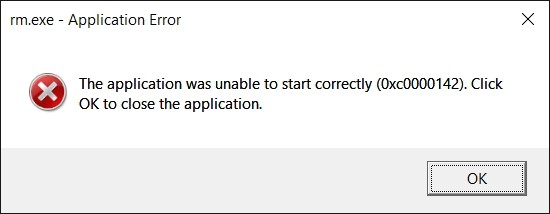
I was determined that my soldering are correct this time round as it is a CMD error & I do not have any short circuits or wrong pins connected.
I gave up on Windows and proceed to use my Library's Mac.
I proceed to install the CROSSPACK, get the firmware.zip & edit the Makefile using Text Editor.
The process was a breeze as compared to Windows.
I *highly recommend* to use MAC or Linux to do the programming for the FABISP.
I decided to use Arduino to be my Programmer ISP as it is readily available in the Makerspace in Library.
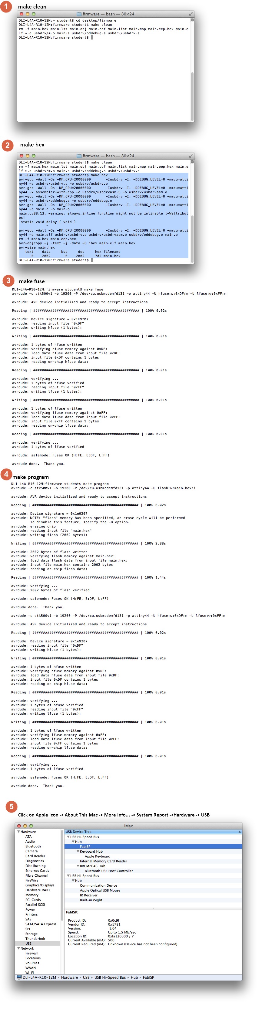
In the MAC environment, I was able to do:
make clean make hex make fuse make program
BUT...
No FABISP was found!
I was able to fuse and program it but no FABISP found.
I even tried removing SJ1 and SJ2. But no avail...
SUDDENLY...
I accidentally broke the 6 PIN GPIO from my FABISP board!
Argh! Annoyed!
A terrible terrible mistake, 3 times the mistake, I broke the chain of unluckiness. I had no choice but to take a spare board from my fellow FabAcademy classmate, Steven, to do transfer the 2nd Board to the new board.
Again, this time I soldered it carefully and double checked for mistakes. And I tried the whole programming process again. But no avail...
I checked the past Fabacademy blogs and everyone's was all bells and whistles. I had to resort on other means...
I began to seek help from past Fabacademy Alumnus of SP, Mark & Siew Chin. They offered their experiences and help to troubleshoot my issues. They even offered their past FABISP to program my board.
My Classmate, Hong Guan offered to do a check on his Ubuntu environment and there was an error when it tried to
make fuse. It stated connection might be shorted, I went back to the Soldering Station and applied more solder and my Classmate Jeff, helped me double checked my board and applied more solder, which we believe could be a cold solder or poor contact.
Alas! when we plugged in my FABISP, it worked! It appeared on my PC and I was delighted!
My heartfelt goes to my fellow support from my Classmates and the Alumnus.
I start to suspect that it could be a poor/ cold solder on the Crystal. Because the could be programmed but not able to function well.
So to recap...TLDR; section
If you did read thru my thought and rants above, Congratulations & Thank you!
If you didn't, no worries, I will still write as detailed as possible, so you wont suffer like me!
Soldering
- When soldering, careful of tiny pins like the Mini USB and the ICs, do them first.- Use the thinnest Solder Tin, Tweezers, Solder Flux, Soldering wick and Fine Tip Soldering Iron. Use a Rework station if you have to and a Magnifying Glass with light is a MUST!
- Use Blutacks if needed to hold down your board. Set soldering iron to 200 Degrees Celsius.
- Exhale when soldering, it helps in steadying your hands while soldering.
- Give slightly more solder to the Clock Oscillator component and make sure all pins are shiny! Dry or dull solder is a Big no-no!
- When in doubt, use the heat gun to run the solders to make sure it is flowing well.
Programming
If you do not have a programmer board, but only Arduino.
Prep
- Use a Mac / Ubuntu *RECOMMENDED*- Download the CROSSPACK & extract to the desktop
- Install Arduino IDE, firmware.zip and xCode
- Connect Wires from Arduino to your FABISP
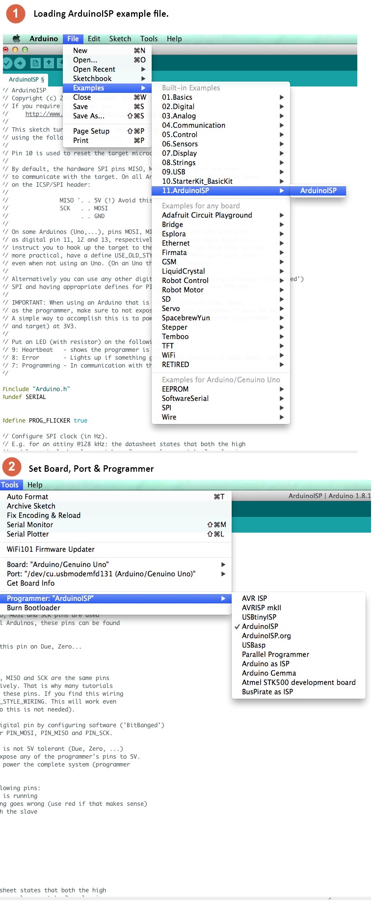
- Prepare your Arduino:
1) Select Tools -> Arduino Uno/ Genduino
2) Select Tools -> Port (select your port)
3) Select Tools -> Programmer -> Arduino as ISP
4) Select File -> Examples -> ArdunioISP -> ArduinoISP
5) Upload the file to Arduino
Connection of Arduino to FABISP
| Uno | FABISP |
|---|---|
| 10 | Reset |
| 11 | MOSI |
| 12 | MISO |
| 13 | SCK |
| 5V | VTG |
| GND | GND |
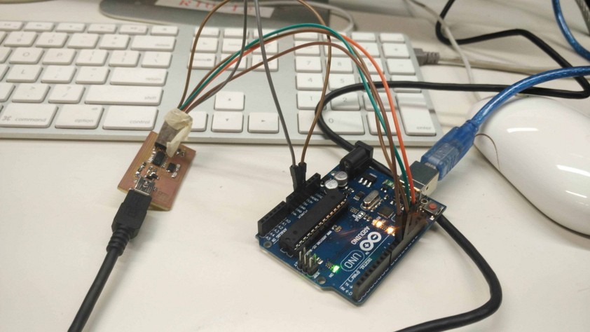
Arduino to FABISP
- Connect the both Arduino and FABISP to the MAC- Open up Makefile in Firmware folder using Text Editor
- comment this line by adding a # infront:
AVRDUDE = avrdude -c avrisp2 -P usb -p $(DEVICE) - add this line after the code code above:
AVRDUDE = avrdude -c stk500v1 -b 19200 -P yourArduinoPortNumber -p $(DEVICE) # For Arduino ISP- Save the file,
Command+S- Open Terminal (you can search it at the magnifying glass on the top right hand side in MAC and type Terminal)
- Open the Desktop directory
cd Desktop/firmware- Firstly type :
make clean- Next:
make hex - Then:
make fuse - Finally:
make program